Sign In
Upload
Manuals
Brands
OMRON Manuals
Software
CJ2 - 02-2010
OMRON CJ2 - 02-2010 Manuals
Manuals and User Guides for OMRON CJ2 - 02-2010. We have
1
OMRON CJ2 - 02-2010 manual available for free PDF download: User Manual
OMRON CJ2 - 02-2010 User Manual (640 pages)
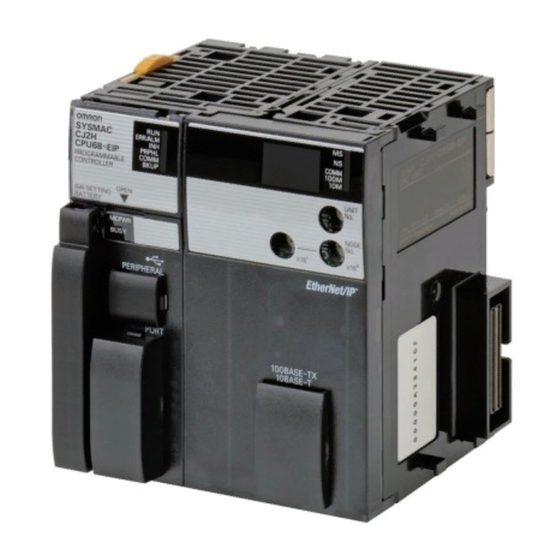
CJ2 CPU Unit Software
Brand:
OMRON
| Category:
Software
| Size: 21.12 MB
Table of Contents
Table of Contents
13
Introduction
5
Intended Audience
5
CJ2 CPU Unit Manuals
6
Manual Structure
9
Additional Information
9
Sections in this Manual
11
Table of Contents
13
Safety Precautions
25
Application Precautions
29
Operating Environment Precautions
34
Regulations and Standards
35
Unit Versions of CJ2 CPU Units
37
Related Manuals
42
1 Overview
45
CJ2 CPU Unit Features
45
Overview of CJ2 CPU Units
45
Overview of CJ2 CPU Units
46
Overview
46
Overview
47
CJ2 CPU Unit Features
48
Basic Operating Procedure
55
2 Internal Memory in the CPU Unit
57
Overview
58
Memory Configuration
58
Built-In Flash Memory
58
Built-In Ram
58
Memory Areas and Stored Data
59
Transferring Data from a Programming Device to the CPU Unit
60
CPU Unit Operation
61
CPU Unit Operating Modes
61
CPU Unit Internal Operation
62
Overview
62
Startup Initialization
62
Cycle Time
64
Program Execution
64
I/O Refreshing
66
Processing at Power Interruptions
67
CPU Unit Operating Modes
68
Operating Modes
68
Checking the Operating Mode
69
Changing the Operating Mode
70
Operating Mode Details
74
CPU Unit Initialization
75
Overview of CPU Unit Initialization
76
CPU Unit Initial Settings
76
CPU Unit Initialization
76
Dip Switch
76
Plc Name
78
Routing Tables
79
PLC Setup
82
Creating I/O Tables
83
I/O Tables
83
Automatic Allocation
84
Manual Allocation
84
Setting Routing Tables
85
Routing Tables
85
Local Network Table
86
Relay Network Table
86
Cases in Which Routing Tables Are Required
87
Setting and Transferring Routing Tables
88
Setting Allocated DM Area Words for Special I/O Units
89
Setting Allocated DM Area Words for Special I/O Units and CPU Bus Units
89
Setting Procedure
89
CPU Bus Unit Setup Area
90
Setting Procedure
90
Understanding Programming
91
Programming
93
Programming Overview
93
Program Capacity
95
Basic Ladder Diagram Concepts
96
ST Language
98
SFC Overview
99
Tasks
101
Overview of Tasks
101
Cyclic Tasks
104
Cyclic Task Status
106
Task Control Instructions
107
Interrupt Tasks
110
External Interrupts
117
Designing Tasks
118
Flags Related to Tasks
121
Sections
128
Overview of Sections
128
Function Blocks
130
Features of Function Blocks
130
Function Block Specifications
132
Symbols
135
Overview
135
Types of Symbols
136
Variables in Function Blocks
137
Global Symbols
138
Local Symbols
138
Network Symbols
139
Network Symbols (CJ2H-CPU6@-EIP and CJ2M-CPU3@ Only)
139
Variables in Function Blocks
143
Symbol Data Types
144
Specifying Arrays
145
Automatic Address Allocation to Symbols
149
Instructions
150
Basic Understanding of Instructions
150
Instruction Conditions
151
Instruction Location and Execution Conditions
152
Instruction Variations
153
Execution Conditions
153
Specifying Operands
157
Specifying Operands
159
Data Formats
165
I/O Refresh Timing
169
Cyclic Refresh
169
Index Registers
174
What Are Index Registers
174
Using Index Registers
174
Processing Related to Index Registers
178
Monitoring Index Registers
179
Sharing Index and Data Registers between Tasks
180
Specifying Address Offsets
182
Overview
182
Examples of Address Offset Application
185
Checking Programs
186
Errors During CX-Programmer Input
186
Program Checks with the CX-Programmer
186
Debugging with the Simulator
187
Error Simulation Function
189
Program Execution Check
190
Precautions
193
Condition Flags
193
Special Program Sections
198
I\/O Memory Areas
203
I/O Memory Areas
203
I/O Memory Area Overview
204
I/O Memory Areas
204
I/O Memory Area Structure
206
Holding I/O Memory Values
208
I/O Area
210
Input Bits
210
Output Bits
212
Data Link Area
215
Synchronous Data Refresh Area
216
CPU Bus Unit Area
217
Special I/O Unit Area
218
Serial PLC Link Area
219
Devicenet Area
220
Work Area
221
Holding Area
222
Self-Maintaining Bits
222
Auxiliary Area
224
Temporary Relay Area
225
Data Memory Area
226
Extended Data Memory Area
229
Automatic Address Allocation
229
File Memory
230
Trace Memory
230
Timer Areas
233
Counter Areas
235
Task Flags
236
Index Registers
237
Data Registers
242
Condition Flags
244
Clock Pulses
246
File Operations
249
File Memory
250
File Operations
250
Types of File Memory
250
Initializing File Memory
251
Memory Card Precautions
253
Memory Card Recognition Time
253
Types of Files Stored in File Memory
255
File Types
255
Program/Network Symbol File
255
Parameter File
256
Data File
256
Comment File
257
Program Index File
257
Unit Backup File
257
Creating and Saving Files for File Memory
258
File Memory Operations
259
Types of File Memory Operations
259
Backup Restore Operation
260
File Memory Operating Procedures and File Memory Files
261
Files Automatically Transferred at Startup
261
General-Purpose Files
263
Restrictions on File Use
267
File Sizes
268
Relation between Support Software and File Memory Files
269
I\/O Allocations and Unit Settings
271
I/O Allocations
271
I/O Allocations
272
Automatic Allocation
275
Manual Allocation
279
Allocating First Words to Racks
284
I/O Table Errors and Precautions
287
Setting CPU Bus Units and Special I/O Units
290
Setting Parameters
290
Data Exchange
294
Special I/O Units
294
Fins Commands
295
Cpu Bus Units
296
Plc Setup
299
Overview of the PLC Setup
300
PLC Setup Settings
302
PLC Setup Settings
303
Startup Operation Settings
303
Iom Hold Bit Startup Hold Setting
304
Execution Setting
305
CPU Unit Settings
306
Execute Process
306
Background Execution Settings
310
Retry Counts
311
Timings/Synchronous Settings
312
Watch Cycle Time
312
Scheduled Interrupt Interval
314
Power off Detection Delay Time
315
Power off Interrupt Disabled
316
Special I/O Unit Cyclic Refreshing
317
Disable Siou Cyclic Refresh
317
Basic I/O Unit Rack Response Times
319
Serial Port Settings
321
Peripheral Service
328
Set Time to All Events
328
FINS Protection
329
Settings for Fins Write Protection Via Network
329
10 CPU Unit Functions
331
Clock Functions
333
Times Stored in Memory
334
Power on Clock Data
334
Power Interruption Time
335
Total Power on Time
335
Free-Running Timers
336
Cycle Time/High-Speed Processing
337
Minimum Cycle Time
337
Maximum Cycle Time
338
Monitoring the Cycle Time
339
High-Speed Inputs
339
Background Execution
340
Programming Example
346
High-Speed Interrupt Function
349
Startup Settings and Maintenance
352
Holding Settings for Operating Mode Changes and at Startup
352
Power off Detection Delay Setting
354
Disabling Power off Interrupts
355
RUN Output
356
Automatic Transfer at Startup
357
Unit Management Functions
365
Basic I/O Unit Management
365
CPU Bus Unit Flags/Bits
367
Special I/O Unit Flags/Bits
368
Memory Management Functions
369
Automatic Backup
369
EM File Memory Functions
371
Comment Memory
372
Replacing the Entire Program During Operation
373
Example Programs
376
Security Functions
380
Write-Protection Using the DIP Switch
380
Read Protection Using Passwords
380
Operating Procedure
381
Enabling/Disabling Saving to Memory Cards
383
Enabling and Disabling Program Overwriting
384
Program Operation Protection Using Production Lot Numbers
385
Write Protection from FINS Commands
386
PLC Names
390
Debugging
393
Forced Set/Reset
393
Test Input
394
Differential Monitoring
394
Online Editing
395
Turning off Outputs
397
Tracing Data
398
Storing the Stop Position at Errors
403
Failure Alarm Instructions
404
Simulating System Errors
405
Failure Point Detection
406
Synchronous Unit Operation
408
Overview
408
Application Example
410
Details on Synchronous Unit Operation
411
Synchronous Unit Operation Specifications
414
Synchronous Data Refresh
415
Restrictions in Using Synchronous Unit Operation
419
Application Procedure
421
PLC Setup
422
Writing the Synchronous Interrupt Task
424
Adjusting and Troubleshooting Synchronous Unit Operation
425
Programming Devices and Communications
429
Accessing a PLC from the CX-Programmer
430
Overview
430
System Configurations for Accessible Plcs
432
Accessing a PLC from the CX-Programmer
436
Automatic Online Connection
439
Serial Communications
443
Overview of Serial Communications
443
No-Protocol Communications System
445
Host Link Fins
447
Operating Specifications
449
System Configuration
449
Communications Networks
457
CPU Unit Cycle Time
461
Monitoring the Cycle Time
462
Computing the Cycle Time
464
CPU Unit Operation Flowchart
464
Cycle Time Overview
465
I/O Unit Refresh Times for Individual Units
467
Cycle Time Calculation Example
471
Online Editing Cycle Time Extension
473
I/O Response Time
473
Response Time for Built-In Input Interrupts
474
Response Performance of Serial PLC Links
475
Appendices
477
Instruction Functions
479
A-1-1 Sequence Input Instructions
479
A-1-2 Sequence Output Instructions
481
A-1-3 Sequence Control Instructions
482
A-1-4 Timer and Counter Instructions
486
A-1-5 Comparison Instructions
490
A-1-6 Data Movement Instructions
494
A-1-7 Data Shift Instructions
496
A-1-8 Increment/Decrement Instructions
500
A-1-9 Symbol Math Instructions
500
A-1-10 Conversion Instructions
505
A-1-11 Logic Instructions
511
A-1-12 Special Math Instructions
513
A-1-13 Floating-Point Math Instructions
514
A-1-14 Double-Precision Floating-Point Instructions
518
A-1-15 Table Data Processing Instructions
521
A-1-16 Tracking Instructions
525
A-1-17 Data Control Instructions
526
A-1-18 Subroutine Instructions
530
A-1-19 Interrupt Control Instructions
531
A-1-20 Step Instructions
532
A-1-21 Basic I/O Unit Instructions
532
A-1-22 Serial Communications Instructions
535
A-1-23 Network Instructions
537
A-1-24 File Memory Instructions
539
A-1-25 Display Instructions
540
A-1-26 Clock Instructions
541
A-1-27 Debugging Instructions
542
A-1-28 Failure Diagnosis Instructions
542
A-1-29 Other Instructions
543
A-1-30 Block Programming Instructions
544
A-1-31 Text String Processing Instructions
548
A-1-32 Task Control Instructions
551
A-1-33 Model Conversion Instructions
551
A-1-34 Special Function Block Instructions
552
Instruction Execution Times and Number of Steps
554
A-2-1 Sequence Input Instructions
555
A-2-2 Sequence Output Instructions
555
A-2-3 Sequence Control Instructions
556
A-2-4 Timer and Counter Instructions
557
A-2-5 Comparison Instructions
558
A-2-6 Data Movement Instructions
559
A-2-7 Data Shift Instructions
560
A-2-8 Increment/Decrement Instructions
561
A-2-9 Symbol Math Instructions
561
A-2-10 Conversion Instructions
563
A-2-11 Logic Instructions
565
A-2-12 Special Math Instructions
565
A-2-13 Floating-Point Math Instructions
565
A-2-14 Double-Precision Floating-Point Instructions
567
A-2-15 Table Data Processing Instructions
568
A-2-16 Tracking Instructions
570
A-2-17 Data Control Instructions
570
A-2-18 Subroutine Instructions
571
A-2-19 Interrupt Control Instructions
571
A-2-20 Step Instructions
572
A-2-21 Basic I/O Unit Instructions
572
A-2-22 Serial Communications Instructions
573
A-2-23 Network Instructions
574
A-2-24 File Memory Instructions
574
A-2-25 Display Instructions
574
A-2-26 Clock Instructions
574
A-2-27 Debugging Instructions
575
A-2-28 Failure Diagnosis Instructions
575
A-2-29 Other Instructions
576
A-2-30 Block Programming Instructions
576
A-2-31 Text String Processing Instructions
578
A-2-32 Task Control Instructions
579
A-2-33 Model Conversion Instructions
579
A-2-34 Special Function Block Instructions
579
A-2-35 SFC Instructions
579
A-2-36 Function Block Instance Execution Time
580
Auxiliary Area
582
A-3-1 Read-Only Area (Set by System
582
A-3-2 Read/Write Area (Set by User
605
Details on Auxiliary Area Operation
614
Memory Map of PLC Memory Addresses
617
PLC Memory Addresses
617
A-4 Memory Map of PLC Memory Addresses
617
Memory Map
618
Operation for Power Interruptions
619
A-5-1 Power off Operation
619
Description of Operation
620
A-5-2 Instruction Execution for Power Interruptions
621
Vista
623
A-6-1 Changing Windows Firewall Settings
623
PLC Comparison Charts: CJ-Series and CS-Series Plcs
626
Functions Supported for Unit Versions
630
Index
633
Revision History
637
Advertisement
Advertisement
Related Products
OMRON CX-ONE - INTRODUCTION GUIDE
Omron SYSMAC CP1E-N Series
Omron CX-Process Monitor Plus 2
Omron SYSMAC CXONE-AL**D-V3
Omron CX-Motion-NCF 1.8
Omron CX-Integrator 2.3
Omron CX-Integrator 1.1
Omron CX-Process Tool 5.2
Omron CX-Designer 3
OMRON CJ2M-CPU3 - 10-2010
OMRON Categories
Blood Pressure Monitor
Controller
Accessories
Switch
Inverter
More OMRON Manuals
Login
Sign In
OR
Sign in with Facebook
Sign in with Google
Upload manual
Upload from disk
Upload from URL