Sign In
Upload
Manuals
Brands
Olympus Manuals
Measuring Instruments
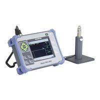
Magna-Mike 8600
Olympus Magna-Mike 8600 Thickness Gauge Manuals
Manuals and User Guides for Olympus Magna-Mike 8600 Thickness Gauge. We have
1
Olympus Magna-Mike 8600 Thickness Gauge manual available for free PDF download: User Manual
Olympus Magna-Mike 8600 User Manual (186 pages)
Hall-Effect Thickness Gauge
Brand:
Olympus
| Category:
Measuring Instruments
| Size: 3 MB
Table of Contents
Table of Contents
3
List of Abbreviations
9
Figure I-1 Labels Attached to the Instrument
11
Labels and Symbols
11
Table 1 Content of the Instruction, Rating, and Serial Labels
12
Figure I-2 the Location of the Warning Symbol on the Top of the Instrument
14
Important Information - Please Read before Use
15
Intended Use
15
Instruction Manual
15
Instrument Compatibility
16
Repair and Modification
16
Safety Symbols
17
Safety Signal Words
17
Note Signal Words
18
Safety
19
Warnings
19
Precautions with Magnets
20
Battery Precautions
21
Equipment Disposal
22
CE (European Community)
22
WEEE Directive
22
China Rohs
23
Korea Communications Commission (KCC)
23
EMC Directive Compliance
23
FCC (USA) Compliance
23
ICES-001 (Canada) Compliance
24
Information Screens
24
Warranty Information
25
Technical Support
26
Figure I-3 the Magna-Mike 8600 Thickness Gage
27
Introduction
27
1 Instrument Overview
29
Operating Principle
29
Package Contents
30
Figure 1-1 Transport Case Contents
31
Figure 1-2 the Standard or Extended Range Calibration Kit
31
Connectors
32
Figure 1-3 the Magna-Mike 8600 Connections
32
Figure 1-4 the Top End Connectors
33
Figure 1-5 the Connectors Behind the I/O Door
33
Power Requirements
34
Figure 1-6 the RS-232 and VGA out Connectors
34
Charger/Adaptor
35
Figure 1-7 Location of the Magna-Mike 8600 Power Key and Indicator Light
35
Figure 1-8 Connecting the Charger/Adaptor
36
Figure 1-9 Connecting the DC Power Plug
36
Optional Lithium-Ion Battery
37
Table 2 Charger/Adaptor and Battery Indicators
37
Alkaline Batteries
38
Figure 1-10 Removing the Lithium-Ion Battery
38
Figure 1-11 Removing the Battery Compartment Cover and the Lithium-Ion Battery
39
Figure 1-12 the Alkaline Battery Holder
39
Optional Microsd Card
40
Figure 1-13 Installing the Microsd Card
40
Magna-Mike 8600 Hardware Features
41
Hardware Overview
41
Figure 1-14 Overview of the Magna-Mike 8600 Hardware - Front View
42
Figure 1-15 Overview of the Magna-Mike 8600 Hardware - Back View
42
Figure 1-16 the Charger/Adaptor Indicator Light on the Front Panel
43
Keypad Configuration
43
Figure 1-17 the English, International, Chinese, and Japanese Keypads
44
Keypad Functions
44
Table 3 Keypad Functions
45
Connectors
47
Probe and Foot Switch Connectors
47
Figure 1-18 Location of the PROBE and FOOT SWITCH Connectors
48
RS-232 and VGA out Connectors
48
Figure 1-19 the RS-232 and VGA out Connectors
49
Microsd and USB Port
49
Figure 1-20 the Microsd Slot and USB Port
50
Battery Compartment
51
Various Hardware Features
51
Figure 1-21 the Battery Compartment
52
Instrument Stand
52
Display Protection
53
Figure 1-22 Instrument Stand
53
O-Ring Gasket and Membrane Seals
53
Environmental Ratings
54
2 Software User Interface Elements
55
Measurement Screen
55
Figure 2-1 the Main Elements of the Measurement Screen
55
Figure 2-2 Example of Other Elements Appearing on the Measurement Screen
56
Menus and Submenus
57
Figure 2-3 Menu and Submenu Example
57
Parameter Screens
58
Figure 2-4 the MEASUREMENT SETUP Screen
58
Editing Text Parameters Using the Virtual Keyboard
59
Figure 2-5 the Virtual Keyboard
59
3 Initial Setup
61
Setting the User Interface Language and Other System Options
61
Selecting the Measurement Units
62
Figure 3-1 the SYSTEM SETUP Screen
62
Setting the Clock
63
Figure 3-2 the MEASUREMENT SETUP Screen - UNITS
63
Changing Display Settings
64
Figure 3-3 the CLOCK SETUP Screen
64
Color Schemes
65
Figure 3-4 the DISPLAY Screen
65
Display Brightness
66
Figure 3-5 Example of the Indoors and the Outdoors Color Schemes
66
Adjusting the Display Update Rate
67
Changing the Thickness Resolution
68
4 Basic and Multipoint Calibration
71
Probe Types
71
Figure 4-1 Standard Straight Probe Model 86PR-1
72
Figure 4-2 Right-Angle Head Probe Model 86PR-2
72
Figure 4-3 Low-Profile Articulating Probe Model 86PR-3
73
Probe Cable Connections
74
Connection to the Magna-Mike 8600
74
Table 4 Probe Cables
74
Connection to the 86PR-1, 86PR-2, and 86PR-3 Probes
75
Replaceable Wear Tips for 86PR-1 and 86PR-2 Probes
75
Wear Tip Replacement
76
Table 5 Wear Tips
76
Proper Target Selection
77
Figure 4-4 the MEASUREMENT SETUP Screen
77
Standard Target Balls
78
Magnetic Target Balls
79
Target Disks
80
Target Wires
80
Table 6 Magna-Mike 8600 Targets
81
Calibration Accessory Kits
82
Table 7 Calibration Kits
83
Calibration Frequency
84
Calibration
85
Table 8 Calibration Accuracy for 86PR-1 and 86PR-2 Probes
85
Table 9 Calibration Accuracy for the 86PR-3 Probe
86
Selecting a Target and Wear Tip
87
Calibrating
88
Figure 4-5 the MEASUREMENT SETUP Screen
88
Figure 4-6 Alignment of Target Ball in Fixture on Probe
89
Figure 4-7 Aligning Disk to Chisel Edge
90
Figure 4-8 THIN SHIM Calibration Point
90
Figure 4-9 THICK SHIM Calibration Point
91
Figure 4-10 Adding Additional Calibration Points
92
Figure 4-11 the MULTIPOINT CALIBRATION Screen
92
Saving and Recalling a Calibration File
93
Table 10 Calibration File Names
93
Measurements
94
Figure 4-12 Recalling a Calibration File
94
Figure 4-13 Correct Method for Thickness Measurements
95
Figure 4-14 Inaccurate Measurement Due to Obstruction of Probe Tip
96
Figure 4-15 Inaccurate Measurement Due to Obstruction of Target Ball
96
Figure 4-16 Inaccurate Measurement Due to Surface Curvature
96
Figure 4-17 Inaccurate Measurement Due to Bad Probe Alignment
97
Other Factors Affecting Accuracy
97
Maintaining Accuracy
98
Q-Cal
98
Periodic Verification
99
Traceability
99
5 Using Special Functions
101
Activating and Configuring a Differential Mode
101
Figure 5-1 Normal Differential Mode
101
Using the Minimum/Maximum Thickness Mode
103
Figure 5-2 the DIFFERENTIAL SETUP Screen
103
Figure 5-3 Displaying the Minimum and Maximum Thicknesses
104
Using Alarms
105
Figure 5-4 the MIN/MAX Screen
105
Figure 5-5 Example of a HIGH Alarm Indicator
106
Using a Strip Chart View
107
Figure 5-6 the ALARM SETUP Screen
107
Figure 5-7 Strip Chart View with and Without Statistics
108
Locking the Instrument
109
Figure 5-8 the STRIP CHART VIEW Screen
109
Figure 5-9 Example of a Locked Function Message in the Help Bar
110
Figure 5-10 the PASSWORD SETUP Screen
110
Figure 5-11 the INSTRUMENT LOCK SETUP Screen
111
6 Configuring the Instrument
113
Configuring Measurement Parameters
113
Figure 6-1 the MEASUREMENT SETUP Screen
113
Configuring System Parameters
115
Activating the Software Upgrade Mode
116
Figure 6-2 the SYSTEM SETUP Screen
116
Configuring Communications
117
Figure 6-3 the UPGRADE Screen
117
Figure 6-4 the COMMUNICATIONS SETUP Screen - RS-232
118
7 Using the Datalogger
121
Datalogger Functions
121
Figure 7-1 the Active File Name Appearing in the Header Bar
121
Table 11 File Contents Summary
122
Table 12 Additional Information Stored with the Data
122
Creating a Data File
123
Data File Types
124
Figure 7-2 the FILE CREATE Screen
124
Incremental Data File Type
124
Table 13 Resulting ID Examples for the INCREMENTAL File Type
125
Figure 7-3 the FILE CREATE Screen for the Incremental Data File Type
126
Sequential Data File Type
127
Table 14 Resulting ID Examples for the SEQUENTIAL File Type
127
Figure 7-4 Selecting the ID Range for the Sequential File Type
128
Sequential Data File Type with Custom Points
128
Table 15 Resulting ID Example for the SEQUENTIAL + CUSTOM File Type
128
Figure 7-5 Configuring the ID Range for a Sequential File with Custom Points
130
Grid Data File Type
130
Figure 7-6 General 2D Grid Example
131
Performing File Operations
132
Figure 7-7 Configuring the ID Range for a 2D Grid Data File Type
132
Figure 7-8 the FILE Menu and REPORTS Submenu
133
Opening a File
133
Copying a File
134
Figure 7-9 Opening a File
134
Editing a File
135
Figure 7-10 Copying a File
135
Deleting a File or Its Contents
136
Figure 7-11 Entering New File Information
136
Figure 7-12 the FILE DELETE Screen
137
Deleting All Data Files
138
Figure 7-13 DATABASE RESET - Warning Message
138
Setting the ID Overwrite Protection
139
ID Review Screen
139
Figure 7-14 the ID# OVERWRITE Protection Message
139
Figure 7-15 the ID REVIEW Screen
140
Editing the ID
141
Reviewing Stored Data and Changing the Active ID
141
Generating Reports
142
Figure 7-16 Editing the ID Number
142
Figure 7-17 the FILE SUMMARY Screen
143
Figure 7-18 the FILE SUMMARY Report Screen
144
Figure 7-19 the MIN/MAX SUMMARY Screen
144
Figure 7-20 the FILE MIN/MAX SUMMARY Report Screen
145
8 Managing Communications and Data Transfer
147
About WINXL
147
Setting up USB Communication
148
Figure 8-1 the COMMUNICATIONS SETUP Screen - USB
148
Setting up RS-232 Serial Communication
149
Figure 8-2 Connecting the Magna-Mike 8600 to a Computer
149
Table 16 Optional RS-232 Cable
150
Exchanging Data with a Remote Device
151
Figure 8-3 the COMMUNICATIONS SETUP Screen - RS-232
151
Figure 8-4 the FILE SEND Screen
152
Sending Entire Files (RS-232)
152
Exporting a File to the Removable Memory Card
153
Sending the Currently Displayed Measurement
153
Figure 8-5 the Connectors Behind the I/O Door
154
Capturing Magna-Mike 8600 Screen Images
155
Figure 8-6 the FILE EXPORT Screen
155
RS-232 Serial Data Output Formats
156
Table 17 Serial Data Output Format for Magna-Mike 8500 and Magna-Mike 8600
156
Figure 8-7 the COMMUNICATIONS SETUP Screen - SEND FORMAT
157
Resetting the Communication Parameters
158
Figure 8-8 the COMMUNICATION RESET Screen
158
Table 18 Default Communication Parameter Values
158
Figure 8-9 the COMMUNICATION RESET Screen - Warning Message
159
9 Maintenance and Troubleshooting
161
Probe
161
Battery (Optional Lithium-Ion)
161
Error Messages
162
Diagnostics
163
Appendix A: Specifications
165
General and Environmental Specifications
165
Table 19 General Specifications
165
Input/Output Specifications
166
Table 20 Environmental Ratings Specifications
166
Table 21 Input/Output Specifications
166
Table 22 Magna-Mike 8600 RS-232 9-Pin Port Output
167
Table 23 Magna-Mike 8600 VGA 15-Pin Port Output
167
Appendix B: Accessories and Replacement Parts
169
Table 24 Accessories and Replacement Parts
169
Table 25 Interface Cables and Power Accessories
169
Table 26 Probes, Probe Cables and Wear Tips
171
Table 27 Targets Balls, Disks, and Wires
171
Table 28 Balls, Disks, and Wires on Fixtures
172
Table 29 Calibration Fixtures for 86PR-1 and 86PR-2 Probes
173
Table 30 Calibration Fixtures for 86PR-3 Probe
173
List of Figures
175
Advertisement
Advertisement
Related Products
Olympus 8080 - CAMEDIA C Wide Zoom Digital Camera
Olympus 80 - Stylus 80 Quartz Date 35mm Camera
Olympus Stylus 830
Olympus Stylus 820
Olympus Stylus 830 - Stylus 830 8MP Digital Camera
Olympus ACCURA SuperZoom 800S
Olympus Stylus 810 - Stylus 810 8MP Digital Camera
Olympus Stylus 800
Olympus Stylus Tough 8000 Blue - Stylus Tough 8000 12MP 2.7 LCD Digital Camera
Olympus Stylus 840
Olympus Categories
Digital Camera
Voice Recorder
Microscope
Camera Accessories
Camera Lens
More Olympus Manuals
Login
Sign In
OR
Sign in with Facebook
Sign in with Google
Upload manual
Upload from disk
Upload from URL