Sign In
Upload
Manuals
Brands
NXP Semiconductors Manuals
Computer Hardware
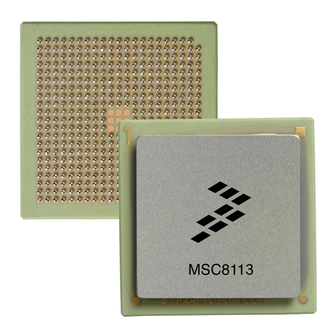
MSC8113
NXP Semiconductors MSC8113 Manuals
Manuals and User Guides for NXP Semiconductors MSC8113. We have
1
NXP Semiconductors MSC8113 manual available for free PDF download: Reference Manual
NXP Semiconductors MSC8113 Reference Manual (1202 pages)
Tri Core 16-Bit Digital Signal Processor
Brand:
NXP Semiconductors
| Category:
Computer Hardware
| Size: 16 MB
Table of Contents
Table of Contents
5
About this Book
21
Audience and Helpful Hints
22
Before Using this Manual-Important Note
22
Notational Conventions and Definitions
23
Conventions for Registers
24
Organization
24
Further Reading
27
Other MSC8113 Documentation
27
MSC8113 Overview
29
Features
30
Architecture
37
Extended Core
38
SC140 Core
39
Instruction Cache
40
M1 Memory
40
Qbus System
42
Extended Core Wait Mode
43
Power Saving Modes
43
60X-Compatible System Bus Interface
44
Extended Core Stop Mode
44
M2 Memory
44
System Interface Unit (SIU)
44
Direct Slave Interface (DSI)
45
Memory Controller
45
Direct Memory Access (DMA) Controller
46
Internal and External Bus Architecture
47
TDM Serial Interface
49
Ethernet Controller
50
Timers
51
Universal Asynchronous Receiver/Transmitter (UART)
51
Gpios
52
Reset and Boot
52
Interrupt Scheme
53
Signal Multiplexing Options
53
Internal Communication and Semaphores
54
Internal Communication
54
Atomic Operations
55
Hardware Semaphores
55
SC140 Core Overview
57
Architecture
58
Data Arithmetic Logic Unit (Data ALU)
59
Data Registers
60
Multiply-Accumulate (MAC) Unit
60
Address Generation Unit (AGU)
61
Bit-Field Unit (BFU)
61
Bit Mask Unit (BMU)
63
Program Sequencer Unit (PSEQ)
63
Stack Pointer Registers
63
Enhanced On-Chip Emulation (Eonce)
64
Programming Model
64
AGU Programming Model
64
Data Arithmetic Logic Programming Model
67
Program Control Unit Programming Model
68
Instruction Set Overview
68
Additional Programming Considerations
75
External Signals
78
Clock Signals
79
Power Signals
79
Reset and Configuration Signals
79
Direct Slave Interface, System Bus, Ethernet, and Interrupt Signals
80
Memory Controller Signals
92
GPIO, TDM, UART, and Timer Signals
94
Dedicated Ethernet Signals
103
Eonce Event and JTAG Test Access Port Signals
103
Reserved Signals
104
System Interface Unit (SIU)
106
Architecture
106
Bus Monitors
107
Timers Clock
108
Time Counter (TMCNT)
108
Periodic Interrupt Timer (PIT)
109
SIU and General Software Watchdog Timers
110
SIU Multiplexing
112
SIU Programming Model
115
Periodic Interrupt Registers
131
Power-On Reset (PORESET)
136
Reset Configuration
138
Reset Configuration through the DSI
138
Reset Configuration through the System Bus
140
Hard Reset
142
Soft Reset
142
Reset Configuration Writes through the System Bus
143
Single MSC8113 System Configuration from EPROM
143
Single Slave MSC8113 Configuration by System Bus Host
144
Multi-MSC8113 System Configuration
144
Multiple MSC8113 Devices in a System with no EPROM
147
Reset Programming Model
147
Hard Reset Configuration Word
147
Reset Status Registers
150
Boot Program
151
Boot Basics
152
Booting from an External Memory Device
153
Booting from an External Host (DSI or System Bus)
154
Booting from the TDM Interface
154
Initializing the TDM Physical Layer
155
Receiver Initialization
156
Transmitter Initialization
157
Messages Structure
158
TDM Logical Layer Handshake
158
Operation
160
Booting from a UART Device
163
Booting from I²C Slave Memory Device
164
Procedure Flow
166
I 2 C System
167
Clocks
169
Clock Generation
170
Board-Level Clock Distribution
171
Single Master Mode Board-Level Clock Distribution
171
Multi-Master Mode Board-Level Clock Distribution
173
Clock Configuration
175
Clocks Programming Model
178
Memory Map
181
SC140 Core Internal Address Space
188
Qbus Address Space
189
Mqbus Address Space
191
Ipbus Address Space
192
Sqbus Address Space
192
Local Bus Address Space
207
System Bus Address Space
235
DSI Address Map
241
Notes
259
Extended Core
261
Pseudo Command Address Space
259
SC140 DSP Core
262
Extended Core Memory (M1)
263
Memory Organization
264
Memory Groups
264
Errors
266
Errors and Exceptions
266
Exceptions
266
Memory Contention and Priority
266
Extended Qbus System
267
Architecture
268
Fetch Unit
269
Qbus Banks
271
Qbus Execution Order
271
Bank Addressing
272
Bank Registers
272
Reservation Process
274
Setting a Data Area
275
Instruction Cacheable Area
277
EQBS Programming Model
278
Instruction Cache (Icache)
284
Icache Attributes
288
Debugging
289
Multi-Task Support
292
Icache Programming Model
293
Commands
294
Modes
294
Reads
295
Restrictions
295
Icache Registers
296
Local Interrupt Controller (LIC)
298
Programmable Interrupt Controller (PIC)
298
Extended Core Power Saving Modes
299
Extended Core Wait Mode
299
Extended Core Stop Mode
299
Mqbus and M2 Memory
301
Mqbus Arbitration Model
302
M2 Memory
303
Reservation Operation
303
Reservation (Atomic) Operation
306
Reservation Operation in the Sqbus Arbiter
307
Reservation Operation on the System Bus
307
Conditions for Failure of the Reservation Operation
307
Memory Controller
309
System Bus Interface
306
Basic Architecture
311
Address and Address Space Checking
316
Page Hit Checking
316
Parity Generation and Checking
316
Transfer Error Acknowledge (TEA) Generation
317
Machine Check Interrupt (MCP) Generation
317
Data Buffer Controls (BCTL[0-1])
317
Atomic Bus Operation
318
Partial Data Valid Indication (PSDVAL)
318
Ecc/Parity Byte-Select (PPBS)
319
Data Pipelining
319
60X-Compatible Mode
320
External Memory Controller Support
320
External Address Latch Enable Signal (ALE)
320
BADDR[27-31] Signal Connections
320
SDRAM Machine
321
Supported SDRAM Configurations
322
SDRAM Power-On Initialization
322
JEDEC-Standard SDRAM Interface Commands
324
Page-Mode Support and Pipeline Accesses
324
Bank Interleaving
325
BNKSEL Signals in Single-MSC8113 Bus Mode
326
SDRAM Address Multiplexing (SDAM and BSMA)
326
SDRAM Read/Write Transactions
328
SDRAM Refresh
328
SDRAM Signals: Device-Specific Parameters
328
SDRAM Signals: General Interface Timing
333
SDRAM Signals: Refresh Timing
336
SDRAM Configuration Examples
337
SDRAM Configuration Example (Page-Based Interleaving)
337
SDRAM Configuration Example (Bank-Based Interleaving)
339
General-Purpose Chip-Select Machine (GPCM)
341
GPCM Signals: Timing Configuration
342
Chip-Select Assertion Timing
342
Chip-Select and Write Enable Deassertion Timing
344
Relaxed Timing
345
Output Enable (POE) Timing
346
Programmable Wait State Configuration
346
Extended Hold Time on Read Accesses
348
GPCM Signals: External Access Termination
350
Boot Chip-Select Operation
352
Differences between Mpc8Xx GPCM and MSC8113 GPCM
352
User-Programmable Machines (Upms)
353
Requests
354
Memory Access Requests
355
UPM Refresh Timer Requests
356
Exception Requests
356
Clock Timing
357
Programming the Upms
357
RAM Array
358
RAM Words
359
Last Word (LAST)
367
Address Multiplexing
367
Data Valid and Data Sample Control
367
Disable Timer Mechanism (TODT)
368
Signal Deassertion
368
Wait Mechanism
368
Extended Hold Time on Read Accesses
369
DRAM Configuration Example
370
Interface Examples
371
Memory System Interface Example Using UPM
371
EDO Interface Example
382
Differences between Mpc8Xx UPM and MSC8113 UPM
390
Handling Devices with Slow or Variable Access Times
390
Hierarchical Bus Interface Example
391
Slow Devices Example
391
External Master Support (60X-Compatible Mode)
391
Strict 60X-Compatible External Masters
392
MSC8113-Type External Masters
392
Extended Controls in 60X-Compatible Mode
392
Address Incrementing for External Bursting Masters
393
External Masters Timing
393
Internal SRAM and Ipbus Peripherals Support
400
UPM Programming Example - Internal SRAM
400
GPCM Programming Example, Ipbus Peripherals
402
Flyby Mode
402
Memory Controller Programming Model
403
System Bus
421
System Bus Signals
421
Address Arbitration
423
Address Start
425
Address Bus
425
Address Transfer Attribute
426
Address Transfer Termination
428
Data Arbitration
429
Data Transfer
430
Data Transfer Termination
432
60X-Compatible Bus Protocols
434
System Bus Operating Modes
434
Single MSC8113 Bus Mode
434
60X-Compatible Bus Mode
436
System Bus Protocols
437
Arbitration Phase
438
Address Pipelining and Split-Bus Transactions
439
Address Tenure Operations
439
Memory Coherency
439
Address Arbitration
440
Address Pipelining
441
Address Transfer Attribute Signals
442
Burst Ordering During Data Transfers
444
Effect of Alignment on Data Transfers
444
Effect of Port Size on Data Transfers
446
60X-Compatible System Bus Mode-Size Calculation
450
Extended Transfer Mode
451
Address Retried with ARTRY Signal
453
Address Transfer Termination
453
Address Tenure Timing Configuration
454
Pipeline Control
455
Data Bus Arbitration
456
Data Streaming Mode
456
Data Tenure Operations
456
Data Bus Transfers and Normal Termination
457
Effect of ARTRY Assertion on Data Transfer and Arbitration
458
Port Size Data Bus Transfers and PSDVAL Termination
458
Data Bus Termination by Assertion of TEA Signal
460
Direct Slave Interface (DSI)
461
Data Bus
463
Data Bus Width
463
DCR[BEM] Bit Access Considerations
464
Address Bus
466
Sliding Window Addressing Mode
466
Full Address Addressing Mode
468
Host Chip ID Signals (HCID[0-3])
470
DSI Endian Modes
470
Host Access Modes and Timings
471
Single Strobe Versus Dual Strobe Access Modes
471
Synchronous Versus Asynchronous Access Mode
472
Burst Transfers
472
Asynchronous Mode Operation
473
Asynchronous Write Using Dual Strobe Mode
473
DSI Access Modes
473
Asynchronous Write Using Single Strobe Mode
475
Asynchronous Read Using Dual Strobe Mode
476
Asynchronous Read Using Single Strobe Mode
477
Synchronous Mode Operation
478
Synchronous Single Write Using Dual Strobe Mode
478
Synchronous Single Write Using Single Strobe Mode
479
Synchronous Single Read Using Dual Strobe Mode
480
Synchronous Single Read Using Single Strobe Mode
481
Synchronous Burst Write Using Dual Strobe Mode
482
Synchronous Burst Write Using Single Strobe Mode
483
Synchronous Burst Read Using Dual Strobe Mode
484
Synchronous Burst Read Using Single Strobe Mode
485
Broadcast Accesses
486
DSI Configuration
487
Stop Mode
488
DSI Reset During Host Access
488
DSI Programming Model
489
Control Registers
489
Status Registers
495
Hardware Semaphores
497
Direct Memory Access (DMA) Controller
499
DMA Signals: Requestor Interface
501
Signal Functionality
501
Peripheral Access Timing
502
DMA Operating Modes: Transfer Types
506
DMA Transfer Size and Peripheral Port Size
506
DMA Access Modes
506
Application Examples
508
External Memory and an External Peripheral on the System Bus
508
External Peripheral to Internal Memory
509
External Peripheral to External Peripheral
510
External Memory and External Memory on the System Bus
511
External Memory to Internal Memory on the System Bus
512
Internal Memory to Internal Memory
513
Flyby Transfer from External Peripheral to External Memory
514
Flyby Transfers between Internal Memories, M2 and M1
515
DMA Operating Modes: Buffer Types
516
Transfers between Internal Memories M1 and M1 (Flyby Mode)
516
Simple Buffer
519
Cyclic Buffer
520
Incremental Buffer
521
Chained Buffer
522
Complex Buffers-Dual Cyclic Buffers
523
Data Transfers
524
DMA Transfer Programming
527
DMA Priority Type
528
Fixed-Priority Mode
528
Round-Robin Priority Mode
528
DMA Arbitration Device Level Considerations
530
DMA Data Transfer Examples
531
Terminating a DMA Transfer
531
DMA Programming Model
532
Configuration Registers
533
DMA Status and Interrupt Registers
540
Bus Error Registers
541
Interrupt Processing
545
Architecture
548
Global Interrupt Controller
548
INT_OUT Generation
550
NMI or NMI_OUT Generation
551
Virtual Interrupt Generation
551
GIC Stop Mode
552
Virtual NMI Generation
552
Local Interrupt Controller (LIC)
553
Resolving LIC Interrupts by the SC140 Cores
555
Level Interrupt Mode
556
DMA Interrupts
557
Edge Interrupt Mode
557
LIC Interrupt Sources
557
Programmable Interrupt Controller (PIC)
561
Interrupt Request Generation
562
Interrupt Routing
562
Peripheral Bus (Qbus) Interface
562
Interrupt Programming Examples
565
Initialization
565
LIC and PIC Programming
566
Clearing Pending Requests
567
Interrupts Programming Model
567
GIC Programming Model
567
LIC Programming Model
573
LIC Interrupt Configuration Registers
574
LIC Interrupt Enable Registers
581
LIC Interrupt Status Registers
582
Edge/Level-Triggered Interrupt Priority Registers
584
Interrupt Priority Structure and Mode
584
PIC Registers
584
Interrupt Pending Registers
587
Overview
592
TAP Controller
594
Instruction Decoding
595
Multi-Core JTAG and Eonce Module Concept
598
Enabling the Eonce Module
599
DEBUG_REQUEST and Enable_Eonce Commands
600
Reading/Writing Eonce Registers through JTAG
600
Signalling a Debug Request
601
EE_CTRL Modifications for the MSC8113
602
Event Selector Register Programming
603
EDCA1_CTRL Register Programming
603
Real-Time Debug Request
604
Exiting Debug Mode
605
Accessing Eonce Registers through JTAG in Real Time
605
External Debug Exception Request
605
Generating a Debug Exception from an EDCA PC Detection Event
606
Tracing in the MSC8113
606
General JTAG Mode Restrictions
607
JTAG and Eonce Module Programming Model
608
Identification Register
608
Boundary Scan Register (BSR)
608
Shift Registers
611
Bypass Register
611
Identification Register
611
General-Purpose Register
612
Parallel Input Register
612
Internal Peripheral Bus (Ipbus)
615
TDM Interface
615
Global Interrupt Controller (GIC)
616
Gpios
616
Hardware Semaphore Registers
616
Timers
616
Uart
616
Direct Slave Interface (DSI)
617
Ethernet Controller
617
Ipbus Functionality
618
Stop Options
618
Ipbus Programming Model
619
TDM Interface
623
Typical Configurations
627
TDM Basics
628
Common Signals for the TDM Modules
630
Receiver and Transmitter Independent or Shared Operation
632
TDM Data Structures
635
Serial Interface
637
Sync out Configuration
637
Sync in Configuration
638
Serial Interface Synchronization
640
Reverse Data Order
642
TDM Local Memory
643
Buffers Mapped on the Local Bus
644
Data Buffer Size and A/M-Law Channels
644
Data Buffer Address
645
Threshold Pointers and Interrupts
648
Unified Buffer Mode
650
Adaptation Machine
651
Channel Activation
653
TDM Power Saving
653
Loopback Support
654
TDM Initialization
655
TDM Programming Model
656
Configuration Registers
658
Control Registers
675
Status Registers
684
System Bus Registers
691
Uart
693
Transmitter
698
Character Transmission
699
Break Characters
701
Idle Characters
702
Parity Bit Generation
702
Receiver
702
Character Reception
703
Data Sampling
704
Framing Error
709
Parity Error
710
Break Characters
710
Baud-Rate Tolerance
710
Slow Data Tolerance
711
Fast Data Tolerance
712
Receiver Wake-Up
712
Address Mark Wake-Up (WAKE = 1)
713
Idle Input Line Wake-Up (WAKE = 0)
713
Reset Initialization
713
Modes of Operation
714
Run Mode
714
Single-Wire Operation
714
Loop Operation
715
Stop Mode
715
Receiver Standby Mode
715
Interrupt Operation
716
UART Programming Model
716
Timers Programming Model
732
Configuration Registers
733
Control Registers
740
Status Registers
741
Gpio
745
Features
745
GPIO Block Diagram
746
Ethernet Functionality of GPIO
748
GPIO Connection Functions
750
GPIO Programming Model
753
I²C Software Module
757
I2C_Txrx_Bit Routine
759
I2C_Txrx_Byte Routine
761
I2C_Read_Sequentialdata Routine
763
I2C_Sample_Gpio Routine
765
I2C_Assert_Start Routine
766
I2C_Assert_Stop Routine
767
I2C_Waitfor_Startcond_Busfreetime Routine
768
I2C_Write_Sequentialdata Routine
769
Ethernet Controller
771
Ethernet Basics
771
Media-Independent Interfaces
775
MSC8113 Ethernet Controller
775
Modes of Operation
776
MII Mode
777
RMII Mode
777
SMII Mode
777
Special Modes
778
Loopback Mode
778
Echo Mode
779
Low-Power Stop Mode
779
Management Interface
779
External Signals
780
Ethernet Controller Interfaces
782
MII
783
MII Transmit Flow
783
MII Receive Flow
784
Rmii
784
RMII Transmit Flow
785
RMII Receive Flow
786
Smii
786
SMII Transmit Flow
787
SMII Receive Flow Mode
789
MAC Control of CSMA/CD
791
Handling Packet Collisions
791
Controlling Packet Flow
792
Controlling PHY Links
792
Frame Recognition
793
Pattern Matching Recognition
793
Destination Address Recognition
795
Hash Table Algorithm
797
Buffer Descriptors
798
Data Buffer Descriptor
798
Receive Frame Processing with Pattern Matching
800
Receive Pattern Matching Filing
801
Filing
805
Transmit Frame Processing with Insertion
806
Flow Control
808
Interrupt Handling
809
Error-Handling
811
Inter-Packet Gap Time
812
Connecting to Physical Interfaces
812
Initialization and Reset
816
Ethernet Controller Programming Model
819
General Control and Status Registers
823
FIFO Control and Status Registers
832
Transmit Control and Status Registers
839
Receive Control and Status Registers
848
MAC Registers
854
MII Management Registers
862
MII Management Address Register
864
MIIGSK Registers
866
RMON Management Information Base (MIB)
875
Hash Function Registers
901
RMON Support
793
Pattern Matching Registers
903
Data Structures (Buffer Descriptors)
907
Programming Reference
921
Register Addressing
921
Interrupts
923
Programming Sheets
928
Advertisement
Advertisement
Related Products
NXP Semiconductors PowerQUICC MPC8308_RDB
NXP Semiconductors MIMXRT1170HDUG
NXP Semiconductors MIMXRT1170
NXP Semiconductors MX93AUD-HAT-UM
NXP Semiconductors MX93AUD-HAT
NXP Semiconductors MCIMX93-EVKCM
NXP Semiconductors MIMXRT1180-EVK
NXP Semiconductors MCXN947VNLT
NXP Semiconductors PowerQUICC MPC857T
NXP Semiconductors MCXN546VNLT
NXP Semiconductors Categories
Motherboard
Microcontrollers
Computer Hardware
Control Unit
Controller
More NXP Semiconductors Manuals
Login
Sign In
OR
Sign in with Facebook
Sign in with Google
Upload manual
Upload from disk
Upload from URL