Sign In
Upload
Manuals
Brands
Novexx Solutions Manuals
Label Maker
ALX 92x
Novexx Solutions ALX 92x Manuals
Manuals and User Guides for Novexx Solutions ALX 92x. We have
1
Novexx Solutions ALX 92x manual available for free PDF download: Service Manual
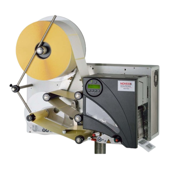
Novexx Solutions ALX 92x Service Manual (824 pages)
Print & Apply system
Brand:
Novexx Solutions
| Category:
Label Maker
| Size: 29 MB
Table of Contents
Using the Documentation
4
Table of Contents
4
Copyright
5
Documentation Structure
6
Datapool, Documentation Object
6
Documentation Concept
6
Using the Documentation
7
Documentation Format
9
Printing the Documentation
10
Navigation Aids
11
Symbols and Note Signs
12
Warning Notes
12
Symbols
13
Text Appearance
13
Title Page
14
Abbreviations
15
Printer Names
15
Parameters
15
Index
16
Machine Operating Safety
24
Installation/Deinstallation
27
Defining the Operating Position
28
Space Requirement
28
Admissible Operation Positions
29
Unpacking and Assembling the Machine
30
Transportation
30
Unpacking the Machine
30
Mounting the Machine on a Support Stand
31
Installing the Unwinder
33
Installing the OD Sensor
34
Electrical Connections
35
Connecting to the Mains Power Supply
35
Connecting to a Data Host
36
Connecting Sensors
37
Rotary Encoder Intallation
40
Installing APSF
42
Principle of Operation
42
Mounting the Rotary Encoder
43
Entering the Rotary Encoder Resolution
44
Entering the Diameter of the Measuring Wheel
44
Entering the Rotary Encoder Type
45
Input of Encoder Data
45
Calibrating the Belt Speed
46
Calculation Scheme for the Automatic Dispensing Speed Adjustment
46
Installing Options
49
Options Overview
49
Remote Operator Panel
50
Pressure Roller
51
Selecting Consumables
52
Thermal Transfer / Direct Thermal Printing .26 Label Material
52
Thermal Transfer Ribbon
53
Decommissioning, Dismantling, Disposal
54
Take the Machine out of Operation
54
Dismantling the Machine
54
Machine Disposal
55
Technical Data
56
Device Types, Use
57
Dpm
57
Pem
57
ALX 92X
57
Options (Electronics Gen. 2)
58
Options (Electronics Gen. 3)
59
Technical Specifications
61
Dimensions
61
Performance Data
63
Thermotransfer Ribbon
66
Automatic Ribbon Economy
67
Labelling Material
69
Mechanical Features
70
Ambient Conditions
71
Connection, Device Data
71
Interfaces (Electronics Gen. 2)
71
Interfaces (Electronics Gen. 3)
72
Electronics Gen. 2
73
Electronics Gen. 3
73
External Sensors
73
Operation
74
Status Messages / Test Functions
74
Advanced Applications
76
Advanced Applications
77
Printing with Temperature Compensation
77
Requirements
77
Function Description
77
Printing with Start Signal
79
Application Notes
79
Available Interfaces
79
Connecting the Signal Source
80
Settings in the Parameter Menu
82
Standalone Operation
83
Requirements
83
Functional Description
84
Selecting Files from Memory Card
85
Executing Printjobs
86
Executing Firmware Files
88
Automatic File Execution
88
Additionally Usable Keys on a Keyboard
88
Insert Input Field in Printjob
89
Example Application
89
Data Input by Interface
91
Data Transmission with Ethernet
92
System Requirements
92
Integration of Ethernet Interface
93
Setting the IP Parameters
94
Transmission with Raw Socket Interface
94
Transmission with LPD Server
95
Troubleshooting
95
Access Via Web/Ftp Server
96
Web Server
96
FTP Server
101
Data Transmission with WLAN
104
Requirements
104
Notes
104
Printer Setup
105
Connecting
105
PC Setup
106
Testing the Connection
107
Sending a Printjob
107
Storing and Transferring Parameter Settings
108
Recommendations
108
Application Cases
108
Storing Settings on Memory Card
109
Loading Settings from Memory Card
110
Automatic Setup Loading
110
Verifying Bar Codes with OLV
111
System Requirements
111
Functional Description
111
Setup
112
Appendix
114
Internal Fonts
120
General Notes
121
System Requirements
121
Font Size
121
OCR-Fonts
121
Parameter Settings
122
Fixfonts and Speedo Fonts
122
Customized Fonts
122
Font Presentation
125
Font Coding Comparison
126
Font Tables
130
Fixfonts
130
Speedo Fonts
181
Fault Location
190
Error Sources
191
Notes about Fault Location
191
Data Transmission
191
Display
191
Gap Detection
192
Material Transport
192
Ribbon, Ribbon Guide
192
Feed Roller, Print Roller
193
Position of the Print Image
193
Print Quality
194
Transport Unit
194
Memory Card
194
Fault Location
191
General Notes
195
Reading out Diagnosis Data
195
Reading out Via Serial Interface
196
Storing on Memory Card
198
Service Mechanics
199
Safety Instructions
201
General Notes
202
Illustrations and Descriptions
202
Factory Settings
202
Key Combinations
203
Service Data
203
Maintenance Plan
204
Performance Interval
204
Cleaning
204
Replacing Wear Parts
204
Visual Inspection
204
Performance Test
205
Housing
206
Front Screen
206
Front Hood
207
DPM Rear Hood
207
Blower (DPM)
209
Rear Hood (ALX)
210
Blower (ALX)
210
Dust Filter (ALX)
211
Hood Switch
212
Material Transport
213
Unwinder (ALX)
213
Deflection Rollers (ALX)
213
Material Dancer Lever (ALX)
214
Contact Pressure Axle at Drawing Roller
215
Contact Axle Sensor
216
Backing Paper Dancer Lever (ALX)
217
Dancer Lever Light Barrier (ALX)
218
Dancer Lever Hall Sensor (ALX)
219
Retrofitting a Hall Sensor Control Unit (ALX)
220
Backing Paper Rewinder (ALX)
224
Rewinder Motor (ALX)
225
Ribbon Transport
226
Important Notes
226
Version Overview
227
Ribbon Unwinding Mandrel (Type 2)
228
Ribbon Unwinding Mandrel (Type 3)
231
Ribbon End Sensor
234
Ribbon Rewinding Mandrel (Type 1/2)
235
Ribbon Rewinding Mandrel (Type 3)
237
Setting Belt Tension
240
Setting Braking Torque
241
Ribbon Motor
244
Ribbon Roller
245
Ribbon Tensioner
245
Print Module
246
Feed Motor (DPM, ALX)
246
Feed Motor (PEM)
247
Brake Roller Version Overview
248
Brake Roller (Type 1 - DPM, ALX)
249
Brake Roller (Type 2 - DPM, ALX)
251
Setting the Braking Torque
255
Print Roller (DPM, ALX)
256
Print Roller (PEM)
257
Print Roller Drive Belt (PEM)
258
Toothed Belt for Feed Roller (DPM, ALX)
258
Feed Roller Drive Belt (PEM)
259
Feed Roller (DPM, ALX)
259
Feed Roller (PEM)
260
Dispensing Edge
261
Guiding Profile
262
Pressure Roller Unit
263
Pressure Roller (PEM)
264
Material Guide
266
Material End Sensor
268
Punch Sensor
269
Printhead
272
General Notes
272
Overview of Printhead Settings
273
Replacing the Printhead
274
Replacing the Printhead Cable
275
Printhead Adjustment
276
Adjusting the Printhead Gap
276
Adjusting the Printhead Position
279
Adjusting the Printhead Contact Pressure
280
Printhead Lifting Mechanism
281
Printhead Pressure Setting Knob
281
Printhead Lift Sensor
282
Boards
283
USI Board (ALX)
283
CPU Board (ALX)
285
USI Board (DPM/PEM)
287
CPU Board (DPM/PEM)
289
Stepper Motor Output Stages
291
Retrofitting M5A Output Stages
292
Operator Panel Board
294
Power Supplies (DPM/PEM)
295
Exchanging the HME Power Supply
295
Exchanging the ME500 Power Supply
297
Retrofitting a ME500 Power Supply
298
Overview Cable Course at ME500 (DPM LH)
302
Overview Cable Course at ME500 (DPM RH)
303
Power Supplies (ALX)
304
Exchanging or Retrofitting the HME/ME500 Power Supply
304
Remote Operator Panel
307
Prerequisites
307
Assembly of Internal Cable (ALX 92X)
307
Assembly of Internal Cable (DPM/PEM)
307
Wall Mounting the Remote Operator Panel
310
APSF-Rotary Encoder
311
Prerequisites
311
Assembly of Internal Cables (DPM/PEM)
312
Connecting
313
Service Electronics Gen. 2
314
General Notes
315
End of Gen. 2 Electronics
315
Upgrade to Gen 3 Electronics
315
Service Electronics Gen
315
Handling Boards
316
ESD Protection
316
Handling
316
CPU Boards
317
Layout Without Ethernet
317
Layout with Ethernet
318
Connectors
319
Output Stage Board
323
Important Notes
323
Layout / Connecting
323
Connectors
324
Option Board
325
Layout
325
Connectors
325
USI Board
326
Application Notes
326
View
327
Connectors
327
Signal Description (D-Sub 15)
328
Pin Assignment Internal Inputs (CN 300)
330
Signal Description (CN300)
331
Pin Assignment Jumper Block
331
Block Diagram
332
Circuit Diagrams for Signal Inputs
333
Input Signals
333
Circuit Diagrams for Signal Outputs
334
Firmware Update
336
USI Testbox
337
Application
337
View
337
Connecting the Test Box
338
Operation
339
Diagram of a USI Input
340
Operation Panel 64-XX
341
Layout
341
Connector
341
Operation Panel DPM/ALX
342
Layout
342
Connector
342
Power Supplies
343
Power Supply Application Notes
343
Me500
346
Characteristics ME500
350
Notes about Retrofitting the ME500
351
Hme Ps 450
352
Characteristics HME PS 450
354
Printhead Voltages
355
Settings
357
Sensor Setting
357
Sensor Test
360
General Notes
360
Sensors on the CPU Board (64-XX)
361
Sensors on the CPU Board (DPM/ALX)
362
Value Table for Sensor 0.12 (Printhead Temp.)
362
Sensors on the Output Stage Boards
363
Options
364
Installing a Memory Extension
364
Installing the Option Board
366
Installing a Realtime Clock
367
Attaching Locking Clips for Flat Strap Plugs
368
Service Electronics Gen. 3
370
General Notes
372
Introduction of „Gen. 3 Electronics
372
Service Electronics Gen. 3
372
Handling Boards
373
ESD Protection
373
Handling
373
CPU Board
374
View
374
Lithium Battery
380
Data Interfaces at the Mounting Plate
381
Sensor Connections
382
Centronics Daughter Board
383
Application Notes
383
View
383
Pin Assignment
384
Compactflash Daughter Board
385
Application Notes
385
View
385
Connecting
386
Operation Panel Boards
387
Application Notes
387
View
387
M4A Output Stage Board
388
Application Notes
388
View
388
Jumper Settings
389
Pin Assignments
389
M5A Output Stage Board
390
Application Notes
390
View
390
Jumper Settings
391
Pin Assignments
392
USI Board
393
Application Notes
393
View
394
Connectors
395
Signals at the D-Sub 15 Connector
395
Application of the Internal Inputs at CN 300
398
Signal Description of the Internal Inputs at CN300
399
Pin Assignment Jumper Block
400
Block Diagram
400
Circuit Diagrams for Signal Inputs
401
Circuit Diagrams for Signal Outputs
402
Replacing the Controller
403
USI Testbox
404
Application Notes
404
View
404
Connecting the Test Box
405
Operation
406
Diagram of a USI Input
407
I/O Board
408
Application Notes
408
View
408
Pin Assignment Serial Interfaces
409
Circuit Diagram RS422 Interface
411
Circuit Diagram RS485 Interface
411
Setting the Interface Parameters
412
Testing the Serial Interface
412
Power Supply Application Notes
413
Nt400
414
Characteristics ME500
420
Hme Ps 450
421
Characteristics HME PS 450
423
Printhead Voltages
424
OD Sensor (ALX 92X)
426
Function
426
System Requirements
426
Assembling the OD-Sensor
427
Connecting the OD-Sensor to AI
429
Connecting the OD-Sensor to USI
431
Settings
436
Material End / Label Sensors
436
Light Sensor at the Rewinder Dancer Lever
439
Hall Sensor at the Rewinder Dancer Lever
444
Adjusting the Imprint Position
447
Sensor Test
448
General Notes
448
Sensors CPU Board (64-XX)
449
Firmware
453
Firmware
454
Show Installed Firmware Version
454
Firmware Components
455
Memory Requirement
455
Taking over Parameter Settings
456
Firmware-Download from the Internet
457
Notes about the Update Procedure
457
Loading from a Compactflash Card
458
In Standalone Mode
458
Starting the Update Automatically
458
Loading Via Data Interface
459
Application Notes
459
System Requirements
459
Installation
459
Starting the Program
460
Forced Bootloader Start
462
Application Notes
462
Procedure
462
Error Messages
463
Printer Firmware
464
About Firmware
465
System Requirements
465
Loaded Firmware Version
467
Download Source
468
Updating Firmware
470
Notes about the Update Procedure
470
Update from a Memory Medium
470
Update Via Data Interface
471
Forced Bootloader Start
472
Error Messages
473
Appendix
474
Installing a Generic Printer on a Windows 7 Host PC for the Purpose of Firmware Upload
474
Applicator Interface
477
Applicator Interface
478
Applicator Operation
478
Connecting an Applicator
480
Selecting an Applicator Type
481
Signal-Time-Diagrams
483
PEP IV / LA-TO Timed / LA-SO
483
PEP Blow on / LA-TO BO Timed
484
Reverse PEP
485
LTP und LTPV
486
PEP II Sensor / LA-TO Sensor / LA-TO BO Sensor
487
Asa / La-Bo
488
Interface Description
489
Important Notes
489
Firmware Requirements
489
Connector Position
490
Connections and Configuration
492
Replacing Older Boards
494
Layout Diagram
495
Circuit Diagrams for Signal Inputs
497
Circuit Diagrams for Signal Outputs
498
Pin Assignments
500
Applicator Connection
500
Novexx-Applicator-Connection
502
Machine Status Connection
503
Product Sensor Connection
505
Signal Leds
507
Table of Contents
510
Please Note -5
512
For Your Safety -5
512
System Requirements -6
513
Installation -7
514
Installation of the AI Retrofitting Kit
514
Installing the External Power Supply Kit -11
518
Exterior Connector -11
518
Connection to the Power Supply -12
519
Power Supply -12
519
Important Setting Instructions
528
Operating the Parameter Menu
530
Parameter Menu
531
Overview Parameter Menus
533
Understanding the Parameter Overviews
533
Printer Status
552
Memory Status
553
Font Status
554
Flashdata Status
557
Service Status
558
Dottest Endless
559
Dottest Punched
559
Reference Label
560
Rfid Status
561
Feed Speed
562
Print Parameters
562
Print Speed
562
Material Length
564
Material Type
564
Material Width
564
Print Direction
565
Punch Offset
565
Bar Code Multip
566
Ean Readline
567
Cut Mode
571
Cut Position
573
Cut Speed
573
Double Cut
573
Punch Mode
575
Punch Level
576
Spooler Mode
577
Interface Delay
578
Offline Mode
578
Printer ID no
578
Spooler Size
578
Serial Port Mode
581
Usb Select
585
Net Mask
586
Ethernet Speed
587
Gateway Address
587
Port Address
587
Snmp Agent
587
Snmp Password
587
Ftp Password
588
Web Display Refr
589
Web Admin Passw
590
Web Supervisor P
590
Time Client
591
Dhcp Host Name
592
Time Server Ip
592
Standalone Input
596
Foil End Warning
599
Foil Warn Stop
599
Print Interpret
602
Character Sets
603
Character Filter
604
Easyplug Error
606
Error Reprint
606
Foil Mode
606
Head Resistance
607
Single Job Mode
607
Thin Line Emphas
610
Voltage Offset
610
Gap Detect Mode
611
External Signal
613
Ram Disk Size
615
Print Info Mode
617
Reprint Function
617
Access Authoriz
618
Realtime Clock
621
Dispense Counter
624
Display Mode
624
Dispensing Mode
625
Start Source
626
Calibration Mode
627
Start Offset
627
Break Diameter
641
Error Polarity
644
Status Output
644
Status Polarity
644
Control Prefix
655
Delimiter Char
655
Format Prefix
655
Label Top
656
Left Position
656
Manual Calibrate
656
Error Checking
657
Error Indication
657
Image Save Path
657
Label Invert
658
Printer Type
660
Delete Job
662
Delete Spooler
662
Store Diagnosis
663
Store Parameters
663
Data Blocks del
664
Log Files Delete
664
Cutter Exchange
666
Head Exchange
666
Roller Exchange
666
Easyplug Monitor
668
Ep Monitor Mode
668
Cutter Test
669
Matend Tolerance
669
Sensor Adjust
669
Feedadjust Label
670
Punch y Calibr
670
Memory Card Test
671
Send Test
672
Receive Test
673
Rewinder Adjust
675
System Date
677
System Revision
677
Cutter Number
680
Head Run Length
680
Roll Number
680
Cuts on Knife
681
Roll Run Length
681
Total Cuts
681
Dispensing Cycl
682
Foil Diameter
682
Head Strobes
682
Head Temperature
682
Operation Time
682
Serial Number
683
Fpga Version
684
Pcb Revision
684
Production Date
684
Board Part Numb
685
Company Name
685
Pcb Part Number
685
Work Place
685
Card Type
686
Display Serialnr
686
Flash Mem Size
687
Space for Jobs
688
Material End
727
Ribbon End
728
Advertisement
Advertisement
Related Products
Novexx Solutions ALX 924 LH
Novexx Solutions ALX 925 LH
Novexx Solutions ALX 924 RH
Novexx Solutions ALX 925 RH
Novexx Solutions ALX 734 LH
Novexx Solutions ALX 735 LH
Novexx Solutions ALX 736 LH
Novexx Solutions ALX 734 RH
Novexx Solutions ALX 735 RH
Novexx Solutions ALX 736 RH
Novexx Solutions Categories
Printer
Label Maker
Printer Accessories
Industrial Equipment
Packaging equipment
More Novexx Solutions Manuals
Login
Sign In
OR
Sign in with Facebook
Sign in with Google
Upload manual
Upload from disk
Upload from URL