Sign In
Upload
Manuals
Brands
Northrop Grumman Manuals
Marine Equipment
naviguide 4000
Northrop Grumman naviguide 4000 Manuals
Manuals and User Guides for Northrop Grumman naviguide 4000. We have
1
Northrop Grumman naviguide 4000 manual available for free PDF download: User, Installation And Service Manual
Northrop Grumman naviguide 4000 User, Installation And Service Manual (253 pages)
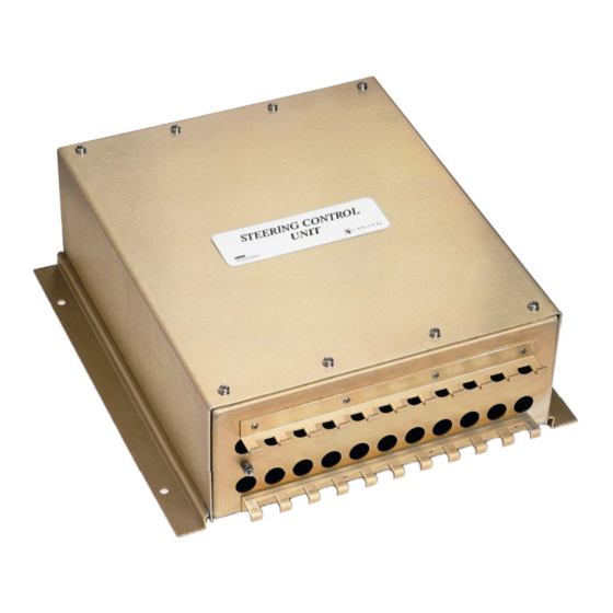
manual steering system with navinet 4000 steering control network
Brand:
Northrop Grumman
| Category:
Marine Equipment
| Size: 8 MB
Table of Contents
Table of Contents
3
1 Description
7
Introduction
7
System Components
8
Steering Control Unit
8
Steering Mode Selector / NFU Tiller
8
Mechanical Mode Switch
8
FU Hand Wheel
9
NFU Override Unit
9
Bus Interface Units (Bius)
10
FU Mini-Wheel/Display Unit
10
FU Interface/Display Unit / Wheel Control Unit
10
Steering Mode Selector Unit
11
Steering Position Selector
11
Dual Rudder Sync Selector
11
Steering Alarm Module
11
NAVINET 4000 Steering Control Network
12
NAVINET 4000 Connection Board
12
NAVINET 4000 Bus Backbone Cable
12
NAVIPILOT 4000 Control and Display Unit (CDU)
13
Example System Configurations
14
FU / NFU Manual Steering for Single Rudder
14
FU / NFU Manual and Autopilot Steering for Single Rudder
15
FU / NFU Manual and Autopilot Steering for Single Rudder (SPS)
16
Dual FU / NFU Manual Steering for Single Rudder
17
Dual FU / NFU Manual and Autopilot Steering for Single Rudder
18
FU / NFU Manual Steering for Dual Rudders
19
Dual FU / NFU Manual Steering for Dual Rudders
20
Technical Data
21
Steering Control Unit (SCU)
21
Dimensions and Weight
22
SCU Daughter Pcbs
23
AC Solenoid Daughter Pcbs
23
DC Solenoid Daughter PCB
23
Isolated Proportional Output PCB
23
Bus Interface Units (Bius)
24
General Concepts
25
Steering Control Operations
25
Engaging / Disengaging Bus Steering
26
Non-Bus Steering Modes
26
Bus Steering Modes
26
Control Transfer between Steering Positions
27
Steering Positions
27
Main Steering Position
27
Remote Steering Positions
27
Steering Control Transfer (Takeover Modes)
28
Call-Up
28
Takeover
29
Steering Mode Changes Due to Control Transfer
30
Operating the Bus Interface Units
31
Control Keys
31
FU Control Devices (3-Key Units)
31
SPS, SMS, DRS and SAM (6-Key Units)
31
Display Screens
32
Steering Mode Selector (SMS)
33
Steering Position Selector (SPS)
34
Dual Rudder Sync Selector (DRS)
35
Steering Alarm Module (SAM)
36
Power-Up Sequence
37
Adjusting the BIU Display Brightness
38
Operating Procedures
39
In Systems with a Mechanical Mode Selector
39
In Systems with a Steering Mode Selector / NFU Tiller
39
Engaging / Disengaging Bus Steering
39
Selecting the Steering Mode
40
Transferring Control between Steering Positions
43
Takeover Transfer Without an SPS, Without Remote Steering Mode
46
Call-Up Transfer with an SPS at Main Only
56
Call-Up Transfer with an SPS at Main and Remote Positions
58
Synchronous / Independent Rudder Control
60
Overriding Bus Steering (NFU Override)
62
Forced Override
62
Jog Override
64
Overriding Auto/Ext. Steering Modes (FU Bus Override)
66
Overriding Auto Steering Mode According to ABS
68
3 Errors and Alarms
71
Audible Warnings from the Bius
71
Single Beep: Invalid Action
71
Three Short Beeps: Takeover Alarm
71
Four Long Beeps: Takeover Reminder Alarm
71
System Alarms
72
Handling System Alarms with the SAM
72
Continuous On-Off Beeping at the SAM: System Alarm
72
Muting the Audible Alarm at the SAM
72
Viewing and Acknowledging Alarms at the SAM
73
List of Alarm Codes and Messages
74
Mechanical Installation
77
Mounting the System Components
77
Adjustment of Steering Gear Feedback Units
77
Electrical Installation
78
Wiring
78
Approved Cable Type
78
NAVINET 4000 Steering Control Network
78
Bus Termination
79
Bus Shielding/Grounding
79
SCU Jumper Configuration
80
DC Daughter PCB Jumper Settings
81
5 System Configuration
83
Configuring the Bus Devices
83
Configuring Steering Positions
83
Devices’ Positions and Names
83
Takeover Mode
84
Configuring the Steering Gear Control
85
Configuring Bang-Bang Steering Control
85
Staging Output Sections
85
Directional / Dump Valve Staging
86
Directional Staging
86
Dump Staging
86
Unswitched / Switched Connection to Solenoid Valves
87
Configuring Analogue Steering Gear Control
88
Output Mode PRO (Proportional to Rudder Order)
88
Output Mode PRE (Proportional to Rudder Error)
88
6 Configuring the Steering Control Unit
89
SCU Setup Menu
89
Accessing the SCU Setup
89
SCU Setup: Overview
91
SCU Setup: Serial Interface
99
Central Alarm Interface
99
Other Serial Interface Settings
99
SCU Setup: Analogue Interface
100
Helm
100
Feedback
101
External System
102
SCU Setup: Ports
103
Mode Ports
103
SCU Ports Joystick
108
SCU Setup: Relays
113
SCU Setup: Steering Gear
116
Maximum Rudder
116
Staging/Dump
116
Analog Output
117
AC Solenoid Board
118
SCU Setup: ABS Override
125
SCU Setup: Helm Advisor
126
SCU Setup: Service Interface
126
SCU Setup: CAN Interface
126
SCU Setup: Main Mode Switch
127
SCU Setup: Alarm Conditions
127
7 Configuring the Bus Interface Units
129
BIU Setup Menus
129
Setup Menu Access Codes
129
Entering the Setup Mode
130
Navigating the Setup Menus
131
Selecting Parameter Settings
132
Toggling Parameters on or off
133
Editing Characters/Numbers
134
Setup of FU Control Units (3-Key-Units)
135
Functional Configuration (Setup 358)
135
Setup 358 – Device Type
136
Basic Configuration (Setup 600)
139
Setup 600 – Basic Settings
142
Setup 600 – Take over
143
Setup 600 – Override
144
Setup 600 – Rudder Settings
145
General CAN Setup and Service Information (Setup 610)
149
Setup 610 – CAN Bus
150
Setup of 6-Key-Units
151
Functional Configuration (Setup 358)
151
Steering Position Selector Basic Configuration (Setup 600)
154
Steering Mode Selector Configuration Options (Setup 600)
158
Dual Rudder Sync Selector Configuration Options (Setup 600)
163
Steering Alarm Module Configuration Options (Setup 600)
168
General CAN Setup and Service Information (Setup 610)
172
8 Service Information
175
SCU Main PCB
175
Location of Diagnostic LED Indicators and Socketed Ics
175
List of Diagnostic LED Indicators
176
List of Socketed Ics
176
Solenoid Daughter Pcbs
177
Location of Diagnostic LED Indicators on Daughter Pcbs
177
List of Diagnostic LED Indicators
177
Setup Tables
179
Steering Position Configuration
183
Drawings
219
Dimension Drawings
219
Standard Connection Diagrams
219
Advertisement
Advertisement
Related Products
Northrop Grumman Categories
Measuring Instruments
Receiver
Amplifier
Marine GPS System
Boating Equipment
More Northrop Grumman Manuals
Login
Sign In
OR
Sign in with Facebook
Sign in with Google
Upload manual
Upload from disk
Upload from URL