Table of Contents
Advertisement
Sperry Marine
User, Installation and Service Manual
NAVIGUIDE 4000
Manual Steering System
with NAVINET 4000 Steering Control Network
Rev. AA, 08 Jan 2004
7-120
056336
Head Office and Freight: Woltmanstrasse 19, D-20097 Hamburg, Germany
Correspondence Address: P.O. Box 10 47 09, D-20032 Hamburg, Germany
Tel.: ++49-40-299 00-0, Fax: ++49-40-299 00-298, E-mail Service: Kai_Stahl@sperry-marine.com
Advertisement
Table of Contents

Subscribe to Our Youtube Channel
Summary of Contents for NORTHROP GRUMMAN naviguide 4000
- Page 1 Sperry Marine User, Installation and Service Manual NAVIGUIDE 4000 Manual Steering System with NAVINET 4000 Steering Control Network Rev. AA, 08 Jan 2004 7-120 056336 Head Office and Freight: Woltmanstrasse 19, D-20097 Hamburg, Germany Correspondence Address: P.O. Box 10 47 09, D-20032 Hamburg, Germany...
- Page 2 056336 Rev. AA NAVIGUIDE 4000 Copyright © Northrop Grumman Sperry Marine, Hamburg, 2004 This document contains proprietary information of Northrop Grumman Sperry Marine, Hamburg, Germany. Any reproduction or publication of this document or any portions thereof without the prior written consent of Sperry Marine is expressly prohibited.
-
Page 3: Table Of Contents
NAVIGUIDE 4000 056336 Rev. AA Contents Description Introduction ......................1–1 System Components....................1–2 1.2.1 Steering Control Unit ..................1–2 1.2.2 Steering Mode Selector / NFU Tiller...............1–2 1.2.3 Mechanical Mode Switch................1–2 1.2.4 FU Hand Wheel ....................1–3 1.2.5 NFU Override Unit ..................1–3 1.2.6 Bus Interface Units (BIUs) ................1–4 1.2.7... -
Page 4: Table Of Contents
056336 Rev. AA NAVIGUIDE 4000 Errors and Alarms Audible Warnings from the BIUs ................3–1 3.1.1 Single Beep: Invalid action................3–1 3.1.2 Three Short Beeps: Takeover Alarm.............. 3–1 3.1.3 Four Long Beeps: Takeover Reminder Alarm..........3–1 System Alarms ...................... 3–2 3.2.1... -
Page 5: Table Of Contents
NAVIGUIDE 4000 056336 Rev. AA Configuring the Bus Interface Units BIU Setup Menus....................7–1 7.1.1 Setup Menu Access Codes ................7–1 7.1.2 Entering the Setup Mode................7–2 7.1.3 Navigating the Setup Menus ................7–3 7.1.4 Selecting Parameter Settings .................7–4 7.1.5 Toggling Parameters On or Off ..............7–5 7.1.6... - Page 6 056336 Rev. AA NAVIGUIDE 4000...
-
Page 7: Introduction
056336 Rev. AA Description Introduction The NAVIGUIDE 4000 Manual Steering System is a Follow-Up (FU) steering con- trol system for marine applications. The system uses the NAVINET 4000 Steering Control Network for communications between the central Steering Control Unit (SCU) and a number of modular control units called Bus Interface Units (BIUs). -
Page 8: System Components
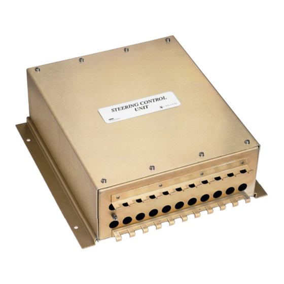
056336 Rev. AA NAVIGUIDE 4000 System Components 1.2.1 Steering Control Unit The Steering Control Unit (SCU) contains an FU control amplifier and all of the system’s in- and output interfaces. Each SCU may be equipped with up to two daughterboards providing the required inter- faces to the vessel’s steering gear. -
Page 9: Fu Hand Wheel
NAVIGUIDE 4000 056336 Rev. AA 1.2.4 FU Hand Wheel FU hand wheels provide follow-up control in the FU bus steering mode. One hand wheel (the main helm) may be connected di- rectly to the Steering Control Interface Unit(s). Additional hand wheels may be used in combination with... -
Page 10: Bus Interface Units (Bius)
056336 Rev. AA NAVIGUIDE 4000 1.2.6 Bus Interface Units (BIUs) 1.2.6.1 FU Mini-Wheel/Display Unit The FU Mini-Wheel/Display Unit (FMW) is a bus FU steering control interface. At the unit currently in com- mand, the mini wheel’s position is translated into FU rudder commands and transmitted to the Steering Con- trol Interface Unit(s) via the bus. - Page 11 NAVIGUIDE 4000 056336 Rev. AA 1.2.6.3 Steering Mode Selector Unit The Steering Mode Selector Unit (SMS) selects be- tween the available bus steering modes. When SMSs are used, one SMS will be located at the main steering position. Additional SMSs may be in- stalled at other steering positions.
-
Page 12: Navinet 4000 Steering Control Network
NAVIGUIDE 4000 1.2.7 NAVINET 4000 Steering Control Network The NAVIGUIDE 4000 SCU and the connected bus interface devices (BIUs and NAVIPILOT 4000 CDUs) communicate through the NAVINET 4000 Steering Con- trol Network, using the NMEA 2000 communications protocol. NAVINET 4000 is is a CAN (Controller Area Network) bus, supporting a maximum bus length of 160 metres. -
Page 13: Navipilot 4000 Control And Display Unit (Cdu)
NAVIGUIDE 4000 056336 Rev. AA 1.2.8 NAVIPILOT 4000 Control and Display Unit (CDU) When a NAVIPILOT 4000 Control and Dis- play Unit (CDU) is added to the NAVIGUIDE 4000, the complete system is referred to as a SteerMaster™ Control System. -
Page 14: Example System Configurations
056336 Rev. AA NAVIGUIDE 4000 Example System Configurations 1.3.1 FU / NFU Manual Steering for Single Rudder Fig.1–1 shows a basic FU / NFU manual steering system (F/NN). Three steering positions are present, Main Bridge (the main steering position), Port Wing and Stb. Wing (the remote steering positions). Selection between steer- ing modes and steering positions is made at the same time using a manual steer- ing mode selector switch. -
Page 15: Fu / Nfu Manual And Autopilot Steering For Single Rudder
NAVIGUIDE 4000 056336 Rev. AA 1.3.2 FU / NFU Manual and Autopilot Steering for Single Rudder Fig.1–2 shows an FU / NFU manual and autopilot steering system (F/NN-AP). This system uses the Steering Mode Selector / NFU Tiller in conjunction with a Steering Mode Selector Unit (SMS). -
Page 16: Fu / Nfu Manual And Autopilot Steering For Single Rudder (Sps)
056336 Rev. AA NAVIGUIDE 4000 1.3.3 FU / NFU Manual and Autopilot Steering for Single Rudder (SPS) Fig.1–3 shows an F/NN-AP system which uses Steering Position Selector Units (SPS) to select the active bus steering position. The SPS at the main steering position will not offer a „Remote“ bus steering mode. -
Page 17: Dual Fu / Nfu Manual Steering For Single Rudder
NAVIGUIDE 4000 056336 Rev. AA 1.3.4 Dual FU / NFU Manual Steering for Single Rudder Fig.1–4 shows a basic dual FU / NFU manual steering system (FF/NN). In contrast to the F/NN system, the FF/NN system contains two SCUs, each of which is controlling a separate steering gear pump. -
Page 18: Dual Fu / Nfu Manual And Autopilot Steering For Single Rudder
056336 Rev. AA NAVIGUIDE 4000 1.3.5 Dual FU / NFU Manual and Autopilot Steering for Single Rudder Fig.1–5 shows a basic dual FU / NFU manual and autopilot steering system (FF/ NN-AP). Steering mode selection and control transfer procedures are the same as for the F/NN-AP system described in 1.3.2. -
Page 19: Fu / Nfu Manual Steering For Dual Rudders
NAVIGUIDE 4000 056336 Rev. AA 1.3.6 FU / NFU Manual Steering for Dual Rudders Fig.1–6 shows a FU / NFU manual steering system for dual rudder control. This is basically the F/NN system described in 1.3.1, but with all rudder control facilities present in twofold. -
Page 20: Dual Fu / Nfu Manual Steering For Dual Rudders
056336 Rev. AA NAVIGUIDE 4000 1.3.7 Dual FU / NFU Manual Steering for Dual Rudders Fig.1–7 shows a Dual FU / NFU manual steering system for dual rudder control. For each of the port and stb. rudders, two SCUs are provided, each of which is controlling a separate steering gear pump. -
Page 21: Technical Data
NAVIGUIDE 4000 056336 Rev. AA Technical Data 1.4.1 Steering Control Unit (SCU) Power Supply primary supply........24 V AC/DC (18-36 V), 3 A backup supply ........24 VDC (18-36 V), 3 A max. ripple content (DC supplies) ..4 Vpp.; extreme values must not exceed 36 V or fall below 18 V power output to autopilot display unit .. - Page 22 056336 Rev. AA NAVIGUIDE 4000 Dimensions and Weight width ............. 413 mm height ............ 400 mm (requires 550 mm minimum clearance for interface cable) depth............. 152 mm (requires 280 mm minimum clearance for cover removal) weight ........... 4.2 kg Page 1–16...
-
Page 23: Scu Daughter Pcbs
NAVIGUIDE 4000 056336 Rev. AA 1.4.2 SCU Daughter PCBs 1.4.2.1 AC Solenoid Daughter PCBs PCB Pn. 20040 (without output enable relays) AC solenoid output ........ 2 separate output sections; solid state relay contacts, 24-230 VAC; max. 4 A in rush, 1 A holding pump status input........ - Page 24 056336 Rev. AA NAVIGUIDE 4000 1.4.3 Bus Interface Units (BIUs) Power Supply power supply......... 24 VDC (18-36 V), 0.2 A (0.3 A max. for SynchroHelm™ FU control devices) max. ripple content ....... 4 Vpp.; extreme values must not exceed 36 V or fall below 18 V...
-
Page 25: General Concepts
2.1.1 Steering Control Operations The NAVIGUIDE 4000 components provide facilities needed to control a vessel’s rudder(s) through one or more SCUs. Depending on the installed components and their configuration, the system will allow a number of the following user operations: –... -
Page 26: Engaging / Disengaging Bus Steering
056336 Rev. AA NAVIGUIDE 4000 2.1.2 Engaging / Disengaging Bus Steering When bus steering is engaged, the outputs of the SCU(s) are connected to the steering gear and the rudder angle(s) are controlled through the SCU(s). When bus steering is disengaged, the outputs of the SCU(s) are disconnected from the steering gear and the rudder(s) are controlled directly through NFU tillers or other control devices. -
Page 27: Control Transfer Between Steering Positions
2.1.3 Control Transfer between Steering Positions The NAVIGUIDE 4000 system allows transfer of rudder control between separate named locations. These are called the steering positions. The positions available and the devices installed at these positions are established through the system configuration, so that only valid control transfer operations can be carried out. - Page 28 NAVIGUIDE 4000 2.1.3.2 Steering Control Transfer (Takeover Modes) The NAVIGUIDE 4000 system provides two different methods for transferring con- trol between the steering positions: Coordinated transfer, referred to as „Call-Up“, and immediate takeover, referred to simply as „Takeover“. Call-Up: When the Call-Up method is configured, control transfer from one posi- tion to another requires a coordinated transfer.
- Page 29 NAVIGUIDE 4000 056336 Rev. AA When a Remote position is active in these systmes, control is offered to other positions by pressing the „Takeover“ key at the Remote position. Offers are then sent to all other positions, including Main. At a called po- sition, control is taken over by pressing the „Takeover“...
- Page 30 056336 Rev. AA NAVIGUIDE 4000 2.1.3.3 Steering Mode Changes due to Control Transfer In most installations, not all steering modes will be available at all steering posi- tions. Hence, when control is transferred from one steering position to another, a change of steering mode may occur.
-
Page 31: Operating The Bus Interface Units
NAVIGUIDE 4000 056336 Rev. AA Operating the Bus Interface Units 2.2.1 Control Keys 2.2.1.1 FU Control Devices (3-key units) Switches back to the previous steering mode after an FU override has been executed at a FU control device Accesses the brightness setting menu Takes over control to this unit’s position... -
Page 32: Display Screens
056336 Rev. AA NAVIGUIDE 4000 2.2.2 Display Screens 2.2.2.1 FU Mini-Wheel / Display, FU Interface / Display, and Wheel Control Units Fig. 2–4: rudder scale FMW, FID, rudder order display rudder order bargraph and WCU display screen ACTUAL 8.2° SB.R... - Page 33 NAVIGUIDE 4000 056336 Rev. AA 2.2.2.2 Steering Mode Selector (SMS) Fig. 0-1 control designation display screen mode 1 mode 2 STEERING MODE FOLLOW UP AUTO REMOTE EXTERNAL mode 3 FU / MAIN mode 4 status line Control Designation: „Steering Mode“ indicates that unit is an SMS...
- Page 34 056336 Rev. AA NAVIGUIDE 4000 2.2.2.3 Steering Position Selector (SPS) Fig. 0-2 control designation display screen position 1 position 2 STEERING POSITION MAIN HELMSMAN PORT WING STBD WING position 3 FU / MAIN position 4 status line Control Designation: „Steering Mode“ indicates that unit is an SPS...
- Page 35 NAVIGUIDE 4000 056336 Rev. AA 2.2.2.4 Dual Rudder Sync Selector (DRS) Fig. 0-3 control designation display screen RUDDER CONTROL RUDDER MODE synchronous independent SYNCHRON INDEPEND FU / MAIN mode selection mode selection status line Control Designation: „Rudder Control / Rudder Mode“ indicates that unit is a Synchronous mode Shows „Synchron“, indicating that the synchronous rud-...
- Page 36 056336 Rev. AA NAVIGUIDE 4000 2.2.2.5 Steering Alarm Module (SAM) Fig. 0-4 display screen in idle and alarm modes Alarm Display Area: Displays pending steering system alarms „Steering System Alarm Display“ shown when no alarm is present (idle mode) Status Line: Always shows the name of the currently active steering position Page 2–12...
-
Page 37: Power-Up Sequence
NAVIGUIDE 4000 056336 Rev. AA 2.2.3 Power-Up Sequence When the steering system is powered-up, each BIU performs a series of self-test routines before entering normal operation: Fig. 0-5 All display segments are briefly activated and a BIU Power-Up ÿÿÿÿÿÿÿÿÿÿÿÿÿÿÿÿÿÿÿ short beep is sounded. -
Page 38: Adjusting The Biu Display Brightness
056336 Rev. AA NAVIGUIDE 4000 2.2.4 Adjusting the BIU Display Brightness The brightness of the BIU display and operating key illumination may be changed through the brightness sub-menu. Press to access the brightness setting menu. Top Right Key: Increases the display brightness. -
Page 39: Operating Procedures
NAVIGUIDE 4000 056336 Rev. AA Operating Procedures The person in charge of navigation must ensure that all personnel have a working knowledge of the steering mode selection and control transfer Warning methods used for the particular installation, including optional override ca- pabilities at devices external to the system. -
Page 40: Selecting The Steering Mode
056336 Rev. AA NAVIGUIDE 4000 2.3.2 Selecting the Steering Mode 2.3.2.1 In Systems with a Mechanical Mode Selector If a mechanical steering mode selector is installed at the main steering position, the desired steering mode is selected and bus steering is engaged/disengaged accordingly through the mechanical selector. - Page 41 NAVIGUIDE 4000 056336 Rev. AA 2.3.2.2 In Systems with a Steering Mode Selector / NFU Tiller If a Steering Mode Selector / NFU Tiller is installed at the main steering position, the desired bus steering mode is selected through the Steering Mode Selector (SMS) bus interface unit.
- Page 42 056336 Rev. AA NAVIGUIDE 4000 If remote steering positions are present, the mechanical steering mode selector may offer a dedicated „Remote“ steering mode. In this case, selecting the „Re- mote“ steering mode initiates control transfer to a remote steering position.
-
Page 43: Transferring Control Between Steering Positions
NAVIGUIDE 4000 056336 Rev. AA 2.3.3 Transferring Control between Steering Positions In the following paragraphs, control transfer procedures are shown for an example system consisting of the Main steering position („Main Bridge“) and two remote steering positions („Port Wing“ and „Stb. Wing“ respectively). Assuming that con-... - Page 44 056336 Rev. AA NAVIGUIDE 4000 2.3.3.1 Call-up Transfer without an SPS, without dedicated Remote steering mode To transfer control from Main to a Remote steering position... At the priority unit at the Main steering position: Press to offer control to all other steering positions.
- Page 45 NAVIGUIDE 4000 056336 Rev. AA Fig. 2–9: Port Wing Main Bridge Stb. Wing Call-up trans- fer, no SPS, no Remote Mode FU / MAIN ACTIVE FU / MAIN READY FOR TAKEOVER OFFERING CONTROL READY FOR TAKEOVER FU / STBD WING...
- Page 46 056336 Rev. AA NAVIGUIDE 4000 2.3.3.2 Takeover Transfer without an SPS, without Remote steering mode To transfer control from Main to a Remote steering position... At the priority unit at the Main steering position: Press to offer control to all other steering positions.
- Page 47 NAVIGUIDE 4000 056336 Rev. AA Fig. 2–10: Port Wing Main Bridge Stb. Wing Takeover trans- fer, no SPS, no Remote Mode FU / MAIN ACTIVE FU / MAIN READY FOR TAKEOVER OFFERING CONTROL READY FOR TAKEOVER FU / STBD WING...
- Page 48 056336 Rev. AA NAVIGUIDE 4000 2.3.3.3 Call-up Transfer without an SPS, with Remote Steering Mode through Mechanical Mode Selector To transfer control from Main to a Remote steering position... At the Main steering position: Select the Remote steering mode at the steering mode selector.
- Page 49 NAVIGUIDE 4000 056336 Rev. AA Fig. 2–11: Port Wing Main Bridge Stb. Wing Call-up trans- fer, no SPS, Remote Mode FU / MAIN ACTIVE FU / MAIN through MMS REMOTE READY FOR TAKEOVER OFFERING CONTROL READY FOR TAKEOVER FU / STBD WING...
- Page 50 056336 Rev. AA NAVIGUIDE 4000 2.3.3.4 Takeover Transfer without an SPS, with Remote Steering Mode through Mechanical Mode Selector To transfer control from Main to a Remote steering position... At the Main steering position: Select the Remote steering mode at the steering mode selector.
- Page 51 NAVIGUIDE 4000 056336 Rev. AA Fig. 2–12: Port Wing Main Bridge Stb. Wing Takeover trans- fer, no SPS, Remote Mode FU / MAIN ACTIVE FU / MAIN through MMS REMOTE READY FOR TAKEOVER OFFERING CONTROL READY FOR TAKEOVER FU / STBD WING...
- Page 52 056336 Rev. AA NAVIGUIDE 4000 2.3.3.5 Call-up Transfer without an SPS, with Remote Steering Mode through SMS To transfer control from Main to a Remote steering position... At the SMS at the Main steering position: Press the softkey assigned to the Remote steering mode.
- Page 53 NAVIGUIDE 4000 056336 Rev. AA Fig. 2–13: Port Wing Main Bridge Stb. Wing Call-up trans- fer, no SPS, FOLLOW UP REMOTE Remote Mode FU / MAIN ACTIVE FU / MAIN through SMS REMOTE FOLLOW UP REMOTE READY FOR TAKEOVER OFFERING CONTROL...
- Page 54 056336 Rev. AA NAVIGUIDE 4000 2.3.3.6 Takeover Transfer without an SPS, with Remote Steering Mode through SMS To transfer control from Main to a Remote steering position... At the SMS at the Main steering position: Press the softkey assigned to the Remote steering mode.
- Page 55 NAVIGUIDE 4000 056336 Rev. AA Fig. 2–14: Port Wing Main Bridge Stb. Wing Takeover trans- fer, no SPS, FOLLOW UP REMOTE Remote Mode FU / MAIN ACTIVE FU / MAIN through SMS REMOTE FOLLOW UP REMOTE READY FOR TAKEOVER OFFERING CONTROL...
- Page 56 056336 Rev. AA NAVIGUIDE 4000 2.3.3.7 Call-Up Transfer with an SPS at Main only To transfer control from Main to a Remote steering position... At the SPS at the Main steering position: Press the softkey assigned to the Remote steering position to which con- trol is to be offered.
- Page 57 NAVIGUIDE 4000 056336 Rev. AA Fig. 2–15: Port Wing Main Bridge Stb. Wing Call-up trans- fer, SPS at MAIN Main only PORT WING STBD WING FU / MAIN ACTIVE FU / MAIN STBD WING MAIN PORT WING STBD WING FU / MAIN...
- Page 58 056336 Rev. AA NAVIGUIDE 4000 2.3.3.8 Call-Up Transfer with an SPS at Main and Remote Positions To transfer control from Main to a Remote steering position... At the SPS at the Main steering position: Press the softkey assigned to the Remote steering position to which con- trol is to be offered.
- Page 59 NAVIGUIDE 4000 056336 Rev. AA Fig. 2–16: Port Wing Main Bridge Main Bridge Stb. Wing Call-up trans- fer, SPS at MAIN MAIN MAIN MAIN MAIN MAIN Main and PORT WING STBD WING PORT WING STBD WING PORT WING STBD WING...
-
Page 60: Synchronous / Independent Rudder Control
056336 Rev. AA NAVIGUIDE 4000 2.3.4 Synchronous / Independent Rudder Control In dual rudder systems, one or more steering positions may be equipped with a DRS and two FUMs. These positions are capable of switching between synchro- nous and independent rudder control. - Page 61 NAVIGUIDE 4000 056336 Rev. AA Fig. 2–17: Port Wheel Stb. Wheel switching between the synchronous ACTUAL 15.0 PT.R ACTUAL 15.0 SB.R FU / STBD WING ACTIVE and independ- SYNCHRON INDEPEND ent rudder con- ACTIVE trol modes SYNCHRON Port Wheel Stb. Wheel...
-
Page 62: Overriding Bus Steering (Nfu Override)
056336 Rev. AA NAVIGUIDE 4000 2.3.5 Overriding Bus Steering (NFU Override) 2.3.5.1 Forced Override When the NFU override unit is installed, the operator may quickly override the bus steering by taking control to the NFU override tiller. During forced override, the bus steering is disengaged and the override tiller actu- ates the stb. - Page 63 NAVIGUIDE 4000 056336 Rev. AA Fig. 2–18: Override Unit NFU Override Tiller Active Steering Position using forced NFU override ACTIVE Prev. Override Mode OVERR. / MAIN Prev. Override Mode OVERR. / MAIN Prev. Override Mode Prev. Mode ACTIVE Prev. Override Mode 2.3: Operating Procedures...
- Page 64 056336 Rev. AA NAVIGUIDE 4000 2.3.5.2 Jog Override If no override unit is installed, the system may be configured for jog override. This configuration will be mostly used when the Steering Mode Selector / NFU Tiller is installed, but may also be used with a conventional NFU tiller.
- Page 65 NAVIGUIDE 4000 056336 Rev. AA Fig. 2–19: NFU Override Tiller Active Steering Position using NFU jog override ACTIVE OVERR. / MAIN ACTIVE 2.3: Operating Procedures Page 2–41...
-
Page 66: Overriding Auto/Ext. Steering Modes (Fu Bus Override)
056336 Rev. AA NAVIGUIDE 4000 2.3.6 Overriding Auto/Ext. Steering Modes (FU Bus Override) If the system is configured for FU bus override, one or more FU Miniwheel or Wheel Control Units at one or more steering positions may temporarily override the Auto and/or the External steering mode. - Page 67 NAVIGUIDE 4000 056336 Rev. AA Fig. 2–20: Autopilot FU Mini-Wheel Unit using FU bus override AUTO / MAIN OVERRIDE ACTIVE AUTO / MAIN 2.3: Operating Procedures Page 2–43...
-
Page 68: Overriding Auto Steering Mode According To Abs
056336 Rev. AA NAVIGUIDE 4000 2.3.7 Overriding Auto Steering Mode according to ABS If the system is configured for ABS override, the handwheel at the Main steering position (the main helm) may temporarily override the Auto steering mode. The ABS override feature conforms to the requirements set out in the „ABS Rules for Building and Classing Steel Vessels“, 4-3-4/13, 2003. - Page 69 NAVIGUIDE 4000 056336 Rev. AA Fig. 2–21: Handwheel (Helm) and Autopilot at Main Steering Mode Selector at Main using ABS override AUTO manual steering mode ACCEPT manual steering mode AUTO 2.3: Operating Procedures Page 2–45...
- Page 70 056336 Rev. AA NAVIGUIDE 4000 Page 2–46 2.3: Operating Procedures...
-
Page 71: Audible Warnings From The Bius
NAVIGUIDE 4000 056336 Rev. AA Errors and Alarms Audible Warnings from the BIUs 3.1.1 Single Beep: Invalid action A single short beep is sounded if the requested action is not permitted in the given situation, e.g. when the operator presses a key assigned to an already active se- lection. -
Page 72: System Alarms
056336 Rev. AA NAVIGUIDE 4000 System Alarms In case of a system alarm, the originating device (SCU, BIU or NAVIPILOT CDU) transmits the corresponding alarm message and code on the NAVINET 4000 Steering Control Network. The SAM and the NAVIPILOT CDU are capable of dis- playing and acknowledging system alarms. - Page 73 NAVIGUIDE 4000 056336 Rev. AA 3.2.1.3 Viewing and Acknowledging Alarms at the SAM When one or more alarms are pending, the last received (newest) alarm message is shown. All pending alarms are stored in a list for viewing and acknowledging.
-
Page 74: List Of Alarm Codes And Messages
056336 Rev. AA NAVIGUIDE 4000 3.2.2 List of Alarm Codes and Messages The table below lists the alarm messages which may occur in a manual steering system. Additional alarms may occur in SteerMaster™ systems, in conjunction with the NAVIPILOT 4000 heading control system. For a complete list of all possi- ble alarms, refer to the NAVIPILOT 4000 Heading Control System manual, Sperry USA document JA19-8039x. - Page 75 NAVIGUIDE 4000 056336 Rev. AA Code Alarm Message Comments Corrective Action MODE SWITCH IO Mode switch in invalid Check mode switch. position. ABS OVERRIDE Given when ABS Over- This alarm indicates that ride function is enabled „ABS Override“ is active.
- Page 76 056336 Rev. AA NAVIGUIDE 4000 Page 3–6 3.2: System Alarms...
-
Page 77: Mechanical Installation
Mechanical Installation 4.1.1 Mounting the System Components Each NAVIGUIDE 4000 system is delivered with a set of dimension drawings for the individual components. Additional detailed installation instructions may be pro- vided by the shipowner or yard. If installation-specific connection drawings are provided, these may also include graphical representations of the placement of control devices at the respective steering positions. -
Page 78: Electrical Installation
At the time of writing of this manual, NAVINET 4000 supports a data transfer rate of 250 kbps. The function of the NAVIGUIDE 4000 system critically depends on the correct in- stallation of the NAVINET 4000 Steering Control Network bus. - Page 79 NAVIGUIDE 4000 056336 Rev. AA 4.2.2.2 Bus Termination The NAVINET 4000 bus must be terminated at both ends with a 120 Ω resistor. Fig. 4–1: NAVINET 4000 Bus Backbone NAVINET 4000 bus termina- tion stubs stubs stubs nodes nodes nodes The SCU and the NAVINET 4000 connection boards contain on-board termination resistors.
-
Page 80: Scu Jumper Configuration
056336 Rev. AA NAVIGUIDE 4000 SCU Jumper Configuration Once the SCU(s) have been installed, jumpers on the main PCBs must be set as required to assign SCU unit IDs and select bus power source and termination. Table 4–1: E1-E2 E15-E16... -
Page 81: Dc Daughter Pcb Jumper Settings
NAVIGUIDE 4000 056336 Rev. AA DC Daughter PCB Jumper Settings The daughter PCBs are installed on the main PCB in the locations indicated in Fig.4–4. If DC Solenoid Daugther PCBs are installed, jumpers must be set to con- figure the PCBs for the required switching mode (source or sink configuration). - Page 82 056336 Rev. AA NAVIGUIDE 4000 Page 4–6 4.4: DC Daughter PCB Jumper Settings...
-
Page 83: Configuring The Bus Devices
At the time of writing of this manual, the NAVIPILOT 4000 CDU is the only bus device capable of accessing the SCU setup menu. With each NAVIGUIDE 4000 system, a CDU will provided for installation pur- poses. In case of manual steering only systems, the CDU used for configuration must be disconnected from the NAVINET 4000 bus during normal operation. - Page 84 056336 Rev. AA NAVIGUIDE 4000 5.1.1.2 Takeover Mode For most systems, the takeover mode (Call Up or Takeover) must be configured for some of the bus devices, i..e. the takeover mode cannot be “none” for all devices. When configuring a steering position, the highest priority device (the „priority unit“) must be determined.
-
Page 85: Configuring The Steering Gear Control
5.2.1.1 Staging Output Sections The NAVIGUIDE 4000 system allows to stage the available solenoid output sec- tions for a given rudder. When staging is used, not all sections are activated at once, but depending on the rudder error (the difference between the ordered and the actual rudder angle), stages above the first stage („Stage 1“) are successively... - Page 86 056336 Rev. AA NAVIGUIDE 4000 5.2.1.2 Directional / Dump Valve Staging When output staging is used, the output sections above Stage 1 may be config- ured either as directional or as dump stages. Directional staging Directional staging is used when each pump section acts on a set of port and star- board solenoid valves.
- Page 87 NAVIGUIDE 4000 056336 Rev. AA 5.2.1.3 Unswitched / Switched Connection to Solenoid Valves The daughter PCBs are available in two versions, unswitched or switched. When unswitched PCBs are used, the output sections are directly connected to the re- spective solenoid valves. In systems with more than one SCU, each SCU controls its own set(s) of solenoids.
-
Page 88: Configuring Analogue Steering Gear Control
SCU requires no rudder feedback signal to generate the output voltage. The rud- der control feedback loop is established outside the SCU, via the analogue steer- ing gear control equipment (third-party supply). Fig. 5–6: NAVIGUIDE 4000 system Analogue Steering Gear analogue out- analogue... -
Page 89: Scu Setup Menu
NAVIGUIDE 4000 056336 Rev. AA Configuring the Steering Control Unit SCU Setup Menu 6.1.1 Accessing the SCU Setup At the time of writing of this manual, the NAVIPILOT 4000 CDU is the only bus de- vice capable of accessing the SCU setup menu. - Page 90 056336 Rev. AA NAVIGUIDE 4000 Navigate through the SCU Configuration menu and SCU CONFIGURATION enter the required settings, using the „∧“, „∨“, „<“, SERIAL INTERFACE ANALOG INTERFACE PORTS „>“, „accept“, „exit“ and „cancel“ softkeys. In some RELAYS STEERING GEAR ABS OVERRIDE...
-
Page 91: Scu Setup: Overview
NAVIGUIDE 4000 056336 Rev. AA 6.1.2 SCU Setup: Overview SCU CONFIGURATION settings for Steering Control Unit(s) serial input interfaces SERIAL INTERFACE CENTRAL ALARM INTERFACE serial data alarm CENTRAL ALARM ENABLED: NO interface disables central alarm interface CENTRAL ALARM ENABLED:YES enables central alarm interface... - Page 92 056336 Rev. AA NAVIGUIDE 4000 contd. from previous page PORTS input port settings (status inputs) MODE PORTS steering mode port settings PORT 1 STANDBY PORT 2 NONE HELM 180 OFFSET GYRO1 180 OFFSET GYRO2 180 OFFSET MAG 180 PORT 180 STBD...
- Page 93 NAVIGUIDE 4000 056336 Rev. AA contd. from previous page SCU PORTS JOYSTICK joystick inputs PORT 1 NONE JOY UP 180 OFFSET GYRO1 180 OFFSET GYRO2 180 OFFSET MAG 180 PORT 180 STBD EN JOYSTICK MUTE PORT 2 NONE JOY DOWN...
- Page 94 056336 Rev. AA NAVIGUIDE 4000 contd. from previous page relay assignments (status outputs) RELAYS RELAY 1 NONE OFF HDG ALARM HDG DIFFERENCE OVERRIDE DEADMAN CONTACT EXT SYS ACTIVE HELM ADVISOR G/M ADVISOR MUTE AUTO (W/OVR) NAV MODE TRACK MODE RELAY 2...
- Page 95 NAVIGUIDE 4000 056336 Rev. AA contd. from previous page steering gear parameters STEERING GEAR MAXIMUM RUDDER maximum rudder angle in bus steering modes max. angle (5 - 120 °) STANDBY STAGING/DUMP stage 1 on/off rudder error thresholds STAGE 1 ON threshold above which stage 1 goes on (0.2 - 2.0°)
- Page 96 056336 Rev. AA NAVIGUIDE 4000 contd. from previous page AC SOLENOID BOARD 2 AC solenoid board 2 configuration PUMP 2 PUMP 1 SCU 1 SCU 1 STAGE 1 STAGE 1 STAGE 2 STAGE 2 STAGE 3 SCU 2 STAGE 4...
- Page 97 NAVIGUIDE 4000 056336 Rev. AA contd. from previous page DC SOLENOID BOARD 2 DC solenoid board 2 configuration PUMP 2 PUMP 1 SCU 1 SCU 1 STAGE 1 STAGE 1 STAGE 2 STAGE 2 STAGE 3 SCU 2 STAGE 4...
- Page 98 056336 Rev. AA NAVIGUIDE 4000 contd. from previous page RS-232 service interface settings SERVICE INTERFACE BAUD RATE 2400 4800 9600 19200 DATA WIDTH 7 BIT 8 BIT PARITY NONE EVEN STOP BITS CAN INTERFACE CAN interface settings BAUD RATE 250K...
-
Page 99: Scu Setup: Serial Interface
NAVIGUIDE 4000 056336 Rev. AA 6.1.3 SCU Setup: Serial Interface 6.1.3.1 Central Alarm Interface Function: Configures the serial data central alarm interface Settings: CENTRAL ALARM ENABLED: NO Disables the central alarm interface. CENTRAL ALARM ENABLED: YES Enables the central alarm interface. For each pending system alarm, the SCU periodically transmits a NMEA „ALR“... -
Page 100: Scu Setup: Analogue Interface
056336 Rev. AA NAVIGUIDE 4000 6.1.4 SCU Setup: Analogue Interface 6.1.4.1 Helm Function: Configures the input for a handwheel connected directly to the SCU(s) at the Main steering position. Settings: HELM ENABLED: NO Disables the helm input. Choose this setting only if no hand- wheel is connected directly to the SCU(s). - Page 101 NAVIGUIDE 4000 056336 Rev. AA 6.1.4.2 Feedback Function: Configures the input for a feedback unit connected to the SCU(s). Settings: FEEDBACK ENABLED: NO Disables the feedback input. Choose this setting only if no feed- back unit ist connected to the SCU(s).
- Page 102 056336 Rev. AA NAVIGUIDE 4000 6.1.4.3 External System Function: Configures the input for an external system connected to the SCU(s). Settings: EXTERNAL SYSTEM ENABLED: NO Disables the external system input. EXTERNAL SYSTEM ENABLED: YES Enables the external system input and accesses the max. angle, polarity and calibration settings to configure the input.
-
Page 103: Scu Setup: Ports
NAVIGUIDE 4000 056336 Rev. AA 6.1.5 SCU Setup: Ports 6.1.5.1 Mode Ports Port 1 Function: Assigns a status sensing function to the status input port 1 („NFU“ port at TB 1.49) Settings: NFU (default) Steering mode NFU is sensed if port is connected to 0V. - Page 104 056336 Rev. AA NAVIGUIDE 4000 Port 2 Function: Assigns a status sensing function to the status input port 2 („Helm“ port at TB 1.50) Settings: NONE Disables the port. HELM (default) Steering mode FU (Helm) is sensed if port is connected to 0V.
- Page 105 NAVIGUIDE 4000 056336 Rev. AA Port 3 Function: Assigns a status sensing function to the status input port 3 („Auto“ port at TB 1.51) Settings: NONE Disables the port. AUTO (default) Steering mode Auto is sensed if port is connected to 0V.
- Page 106 056336 Rev. AA NAVIGUIDE 4000 Port 4 Function: Assigns a status sensing function to the status input port 4 („Remote“ port at TB 1.52) Settings: NONE Disables the port. REMOTE (default) Steering mode Remote is sensed if port is connected to 0V.
- Page 107 NAVIGUIDE 4000 056336 Rev. AA External System Name Function: Selects the name to show as the position/mode designation for the External steering mode. Settings: One of 8 predefined names The selected name will be shown as the active position and mode when the system is operated in the External steering mode.
- Page 108 056336 Rev. AA NAVIGUIDE 4000 6.1.5.2 SCU Ports Joystick Port 1 Function: Assigns a status sensing function to the joystick input port 1 („Joy Up“ port at TB 1.54) Settings: NONE Disables the port. Joy Up (default) not implemented in the current software release.
- Page 109 NAVIGUIDE 4000 056336 Rev. AA Port 2 Function: Assigns a status sensing function to the joystick input port 2 („Joy Down“ port at TB 1.55) Settings: NONE Disables the port. Joy Down (default) not implemented in the current software release.
- Page 110 056336 Rev. AA NAVIGUIDE 4000 Port 3 Function: Assigns a status sensing function to the joystick input port 3 („Joy Right“ port at TB 1.56) Settings: NONE Disables the port. Joy Right (default) not implemented in the current software release.
- Page 111 NAVIGUIDE 4000 056336 Rev. AA Port 4 Function: Assigns a status sensing function to the joystick input port 4 („Joy Left“ port at TB 1.57) Settings: NONE Disables the port. Joy Left (default) not implemented in the current software release.
- Page 112 056336 Rev. AA NAVIGUIDE 4000 6.1.5.3 Override Active In Function: Sets the bus steering modes which may be overriden by executing bus override from an FU Control Bus Interface Unit. Settings: NONE Bus override not allowed. AUTO/NAV/TRACK Bus override allowed in autopilot steering modes only.
-
Page 113: Scu Setup: Relays
NAVIGUIDE 4000 056336 Rev. AA 6.1.6 SCU Setup: Relays 6.1.6.1 Relay 1 Function: Assigns a status output function to relay 1 („Override Alarm“ relay at TB 1.34 - 1.36) Settings: NONE No function assigned. OFF HDG ALARM Relay is energized if „off heading“ condition is true. - Page 114 056336 Rev. AA NAVIGUIDE 4000 6.1.6.2 Relay 2 Function: Assigns a status output function to relay 2 („Mode Status“ relay at TB 1.73 - 1.75) Settings: NONE No function assigned. OFF HDG ALARM Relay is energized if „off heading“ condition is true.
- Page 115 NAVIGUIDE 4000 056336 Rev. AA 6.1.6.3 Relay 3 Function: Assigns a status output function to relay 3 („Off Heading“ relay at TB 1.76 - 1.78) Settings: OFF HDG ALARM (fixed assignment, no options available) Relay is energized if „off heading“ condition is true.
-
Page 116: Scu Setup: Steering Gear
056336 Rev. AA NAVIGUIDE 4000 6.1.7 SCU Setup: Steering Gear 6.1.7.1 Maximum Rudder Max. Angle Function: Sets the absolute maximum for the rudder order that may be com- manded in any bus steering mode (FU, Auto and External). Settings: Max. rudder (5 – 120 °) Set to the required value. - Page 117 NAVIGUIDE 4000 056336 Rev. AA 6.1.7.3 Analog Output Mode Function: Sets the analogue output’s working mode. Settings: PRO Output voltage is proportional to rudder order. Output voltage is proportional to rudder error Polarity Function: Sets the analogue output’s polarity. Settings: STBD. POS Output voltage is positive for starboard rudder order.
- Page 118 056336 Rev. AA NAVIGUIDE 4000 6.1.7.4 AC Solenoid Board 1 (daughter PCB 1 at SCU J2) Pump 1 Function: Configures the PCB’s 1st stage. Settings: SCU 1 STAGE 1 Act as stage 1 in SCU 1. STAGE 2 Act as stage 2 in SCU 1.
- Page 119 NAVIGUIDE 4000 056336 Rev. AA SCU 2 STAGE 1 Act as stage 1 in SCU 2. STAGE 2 Act as stage 2 in SCU 2. STAGE 3 Act as stage 3 in SCU 2. STAGE 4 Act as stage 4 in SCU 2.
- Page 120 056336 Rev. AA NAVIGUIDE 4000 6.1.7.5 AC Solenoid Board 2 (daughter PCB 2 at SCU J3) Pump 1 Function: Configures the PCB’s 1st stage. Settings: SCU 1 STAGE 1 Act as stage 1 in SCU 1. STAGE 2 Act as stage 2 in SCU 1.
- Page 121 NAVIGUIDE 4000 056336 Rev. AA SCU 2 STAGE 1 Act as stage 1 in SCU 2. STAGE 2 Act as stage 2 in SCU 2. STAGE 3 Act as stage 3 in SCU 2. STAGE 4 Act as stage 4 in SCU 2.
- Page 122 056336 Rev. AA NAVIGUIDE 4000 6.1.7.6 DC Solenoid Board 1 (daughter PCB 1 at SCU J2) Pump 1 Function: Configures the PCB’s 1st stage. Settings: SCU 1 STAGE 1 Act as stage 1 in SCU 1. STAGE 2 Act as stage 2 in SCU 1.
- Page 123 NAVIGUIDE 4000 056336 Rev. AA SCU 2 STAGE 1 Act as stage 1 in SCU 2. STAGE 2 Act as stage 2 in SCU 2. STAGE 3 Act as stage 3 in SCU 2. STAGE 4 Act as stage 4 in SCU 2.
- Page 124 056336 Rev. AA NAVIGUIDE 4000 6.1.7.7 DC Solenoid Board 2 (daughter PCB 2 at SCU J3) Pump 1 Function: Configures the PCB’s 1st stage. Settings: SCU 1 STAGE 1 Act as stage 1 in SCU 1. STAGE 2 Act as stage 2 in SCU 1.
-
Page 125: Scu Setup: Abs Override
NAVIGUIDE 4000 056336 Rev. AA SCU 2 STAGE 1 Act as stage 1 in SCU 2. STAGE 2 Act as stage 2 in SCU 2. STAGE 3 Act as stage 3 in SCU 2. STAGE 4 Act as stage 4 in SCU 2. -
Page 126: Scu Setup: Helm Advisor
056336 Rev. AA NAVIGUIDE 4000 6.1.9 SCU Setup: Helm Advisor Function: Enables or disables the Helm Advisor function. Settings: HELM ADVISOR: YES Enables the helm advisor function. HELM ADVISOR: NO Disables the helm advisor function. 6.1.10 SCU Setup: Service Interface Function: Sets the communication parameters for the RS-232 service interface. -
Page 127: Scu Setup: Main Mode Switch
NAVIGUIDE 4000 056336 Rev. AA 6.1.12 SCU Setup: Main Mode Switch Function: Sets the type of steering mode selector installed at the Main steering position. Settings: NONE No steering mode selector installed. Mechanical steering mode selector installed. Steering Mode Selector / NFU Tiller installed. - Page 128 056336 Rev. AA NAVIGUIDE 4000 Page 6–40 6.1: SCU Setup Menu...
-
Page 129: Biu Setup Menus
NAVIGUIDE 4000 056336 Rev. AA Configuring the Bus Interface Units BIU Setup Menus The Bus Interface Units store their configuration parameters in an on-board mem- ory chip. Each unit must be individually configured as required. A complete list of the required settings for each unit will generally be provided with the system-specific installation drawings. -
Page 130: Entering The Setup Mode
056336 Rev. AA NAVIGUIDE 4000 7.1.2 Entering the Setup Mode To access one of the setup menus, a special key combination must be pressed and the required acces code entered as shown in Fig.7–1. Fig. 7–1: From normal operational mode, press the top mid- Entering dle and right keys simultanoeusly. -
Page 131: Navigating The Setup Menus
NAVIGUIDE 4000 056336 Rev. AA 7.1.3 Navigating the Setup Menus In the setup mode, the top three keys are assigned special functions enabling the user to navigate through the respective setup menu and make the appropriate set- tings. In 6-key units, the bottom three keys become inactive in the setup mode. -
Page 132: Selecting Parameter Settings
056336 Rev. AA NAVIGUIDE 4000 7.1.4 Selecting Parameter Settings A number of parameter settings are made by selecting the required value from a list of options, as shown in Fig.7–3. Fig. 7–3: BASIC SETTINGS Selecting Parameter POSITION Settings right key:... -
Page 133: Toggling Parameters On Or Off
NAVIGUIDE 4000 056336 Rev. AA 7.1.5 Toggling Parameters On or Off When a parameter setting is made by enabling or disabling a given function, there will be no sub-menu presented when the parameter is selected. Instead, a tickbox indicates whether the parameter is on or off., which may be toggled directly as shown in Fig.7–4. -
Page 134: Editing Characters/Numbers
056336 Rev. AA NAVIGUIDE 4000 7.1.6 Editing Characters/Numbers When a parameter setting is made by editing a character string or a number, a blinking cursor appears when the edit sub-menu is accessed. The parameter may then be edited and the current cursor position advanced as shown in Fig.7–5. -
Page 135: Setup Of Fu Control Units (3-Key-Units)
NAVIGUIDE 4000 056336 Rev. AA Setup of FU Control Units (3-Key-Units) 7.2.1 Functional Configuration (Setup 358) The settings in the Setup 358 determine the unit’s device type. Before any other settings are made, the Setup 358 must be accessed to set the correct device type. - Page 136 056336 Rev. AA NAVIGUIDE 4000 7.2.1.2 Setup 358 – Device Type Function: Sets the device type according to the type of FU control connected to the unit. Settings: FU MINIWHEEL This setting is always to be chosen for the FU Mini-Wheel/Dis- play Unit (FMW).
- Page 137 NAVIGUIDE 4000 056336 Rev. AA 7.2.1.4 Setup 358 – Options Setup Code Function: Enables or disables the access code protection for the setup menus. Settings: ON Enables code protection for the setup menus. Disables code protection for the setup menus.
- Page 138 056336 Rev. AA NAVIGUIDE 4000 Acoustic Alarm Function: Enables or disables the audible alarm Settings: ON Enables the audible alarm. Always choose this setting. Disables the audible alarm. For factory use only. Never choose this setting for a unit installed on a vessel.
-
Page 139: Basic Configuration (Setup 600)
NAVIGUIDE 4000 056336 Rev. AA 7.2.2 Basic Configuration (Setup 600) 7.2.2.1 Setup 600: Overview SETUP 600 configuration settings for FU steering control units BASIC SETTINGS basic system setup POSITION steering position where this unit MAIN is located PORT WING STBD WING NAV.STAT... - Page 140 056336 Rev. AA NAVIGUIDE 4000 contd. from previous page TAKE OVER takeover settings for this unit selected TAKE OVER MODE takeover mode NONE for this unit TAKE OVER CALL UP setting for TAKE OVER ALARM ÷ takeover alarm = on ö...
- Page 141 NAVIGUIDE 4000 056336 Rev. AA contd. from previous page ELECTRIC SHAFT settings for electric shaft (SynchroHelm systems) MODE electric shaft ÷ on/off = on ö = off WHEEL MID put wheel to midships ÷ when leaving FU mode = on ö...
- Page 142 056336 Rev. AA NAVIGUIDE 4000 7.2.2.2 Setup 600 – Basic Settings Position Function: Assigns the unit to a logical steering position Settings: One of the 12 predefined + 8 user-definable names The selected position name determines which logical steering position the unit is assigned to.
- Page 143 NAVIGUIDE 4000 056336 Rev. AA 7.2.2.3 Setup 600 – Take Over Take Over Mode Function: Selects this unit’s takeover mode. Settings: NONE This unit cannot take or offer control. Choose this setting for all units at a given position except for the priority unit.
- Page 144 056336 Rev. AA NAVIGUIDE 4000 7.2.2.4 Setup 600 – Override Override Function: Enables or disables this unit’s capability to execute FU override of the bus steering modes. Settings: ON This unit may override bus steering. This unit cannot override bus steering.
- Page 145 NAVIGUIDE 4000 056336 Rev. AA 7.2.2.5 Setup 600 – Rudder Settings Rudder Scaling Function: Selects the scaling of the rudder order and act. rudder bargraphs. Settings: 10 - 20 - 30 - 40 Linear scaling for units with a max. rudder angle of 45°.
- Page 146 056336 Rev. AA NAVIGUIDE 4000 Dual Rudder Function: Configures the unit for use in dual rudder systems. Settings: DUAL RUDDER TYPE NONE No dual rudder function available with this unit. This is the re- quired setting for all units in single rudder systems. In dual rud- der systems, this setting is required for units which are not used as port or stbd.
- Page 147 NAVIGUIDE 4000 056336 Rev. AA 7.2.2.6 Setup 600 – Electric Shaft Mode Function: Enables or disables the electric shaft function in SynchroHelm™ sys- tems. Settings: ON Enables the electric shaft function. This is the required setting for SynchroHelm™ units. Disables the electric shaft function. This is the required setting for non-SynchroHelm™...
- Page 148 056336 Rev. AA NAVIGUIDE 4000 7.2.2.7 Setup 600 – Individual Name Select Name Idx. Function: Selects the index of the name to be edited Settings: 0 – 7 The selected index determines which of the 8 user-definable names is edited when the „change sel. name“ menu is called.
-
Page 149: General Can Setup And Service Information (Setup 610)
NAVIGUIDE 4000 056336 Rev. AA 7.2.3 General CAN Setup and Service Information (Setup 610) 7.2.3.1 Setup 610: Overview SETUP 610 CAN bus setup and service information CAN bus communication settings CAN BUS CAN BUS RATE CAN bus baud rate (must be identical... - Page 150 056336 Rev. AA NAVIGUIDE 4000 7.2.3.2 Setup 610 – CAN Bus CAN BUS RATE Function: Selects the communication baudrate for the NAVINET 4000 bus Settings: 50 kb/sec. 50 kb/sec. (currently not supported; do not select) 62.5 kb/sec. 62.5 kb/sec. (currently not supported; do not select) 125 kb/sec.
-
Page 151: Setup Of 6-Key-Units
NAVIGUIDE 4000 056336 Rev. AA Setup of 6-Key-Units 7.3.1 Functional Configuration (Setup 358) The settings in the Setup 358 determine the unit’s device type. Before any other settings are made, the Setup 358 must be accessed to set the correct device type. - Page 152 056336 Rev. AA NAVIGUIDE 4000 7.3.1.2 Setup 358 – Device Type Function: Sets the device type according to the type of FU control connected to the unit. Settings: DUAL RUD. SYNC. SELECT Sets up the device as a Dual Rudder Sync Selector (DRS).
- Page 153 NAVIGUIDE 4000 056336 Rev. AA Powerup Test Function: Enables or disables the test routine at power-up. Settings: ON Enables the power-up test routine. When powering up, the unit will test the ROM, RAM and EEPROM before starting normal op- eration.
-
Page 154: Steering Position Selector Basic Configuration (Setup 600)
056336 Rev. AA NAVIGUIDE 4000 7.3.2 Steering Position Selector Basic Configuration (Setup 600) The Setup 600 contains the SPS’s basic configuration settings. 7.3.2.1 Setup 600: Overview SETUP 600 configuration settings for steering position selector BASIC SETTINGS basic setup of this unit... - Page 155 NAVIGUIDE 4000 056336 Rev. AA contd. from previous page TAKE OVER takeover settings for this unit TAKE OVER ALARM setting for ÷ takeover alarm = on ö = off individual name settings INDIVIDUAL NAME (must be identical throughout the system)
- Page 156 056336 Rev. AA NAVIGUIDE 4000 7.3.2.2 Setup 600 – Basic Settings Position Function: Assigns the unit to a logical steering position Settings: One of the 12 predefined + 8 user-definable names The selected position name determines which logical steering position the unit is assigned to.
- Page 157 NAVIGUIDE 4000 056336 Rev. AA Ext. Sys. Name Function: Selects the name to show as the position/mode designation for the External steering mode. Settings: One of 8 predefined names The selected name will be shown as the active position and mode when the system is operated in the External steering mode.
-
Page 158: Steering Mode Selector Configuration Options (Setup 600)
056336 Rev. AA NAVIGUIDE 4000 7.3.3 Steering Mode Selector Configuration Options (Setup 600) The Setup 600 contains the SMS’s basic configuration settings. 7.3.3.1 Setup 600: Overview SETUP 600 configuration settings for steering mode selector BASIC SETTINGS basic system setup POSITION... - Page 159 NAVIGUIDE 4000 056336 Rev. AA contd. from previous page TAKE OVER takeover settings for this unit TAKE OVER MODE selected takeover mode NONE for this unit TAKE OVER CALL UP TAKE OVER ALARM setting for ÷ takeover alarm = on ö...
- Page 160 056336 Rev. AA NAVIGUIDE 4000 7.3.3.2 Setup 600 – Basic Settings Position Function: Assigns the unit to a logical steering position Settings: One of the 12 predefined + 8 user-definable names The selected position name determines which logical steering position the unit is assigned to.
- Page 161 NAVIGUIDE 4000 056336 Rev. AA Aud. Button Resp. Function: Enables or disables the audible response upon key presses Settings: ON An audible response (beep) is given when a key is pressed at this unit. No audible response is given when a key is pressed at this unit.
- Page 162 056336 Rev. AA NAVIGUIDE 4000 Take Over Alarm Function: Enables or disables the audible takeover alarm. Settings: ON An intermittent audible alarm (three beeps) is given when this unit has issued or received a control offer and no position has taken over control yet.
-
Page 163: Dual Rudder Sync Selector Configuration Options (Setup 600)
NAVIGUIDE 4000 056336 Rev. AA 7.3.4 Dual Rudder Sync Selector Configuration Options (Setup 600) The Setup 600 contains the DRS’s basic configuration settings. 7.3.4.1 Setup 600: Overview SETUP 600 configuration settings for dual rudder sync selector BASIC SETTINGS basic system setup... - Page 164 056336 Rev. AA NAVIGUIDE 4000 contd. from previous page TAKE OVER takeover settings for this unit TAKE OVER MODE selected takeover mode NONE for this unit TAKE OVER CALL UP TAKE OVER ALARM setting for ÷ takeover alarm = on ö...
- Page 165 NAVIGUIDE 4000 056336 Rev. AA 7.3.4.2 Setup 600 – Basic Settings Position Function: Assigns the unit to a logical steering position Settings: One of the 12 predefined + 8 user-definable names The selected position name determines which logical steering position the unit is assigned to.
- Page 166 056336 Rev. AA NAVIGUIDE 4000 7.3.4.3 Setup 600 – Take Over Take Over Mode Function: Selects this unit’s takeover mode. Settings: NONE This unit cannot take or offer control. Choose this setting for all units at a given position except for the priority unit.
- Page 167 NAVIGUIDE 4000 056336 Rev. AA 7.3.4.4 Setup 600 – Individual Name Select Name Idx. Function: Selects the index of the name to be edited Settings: 0 – 7 The selected index determines which of the eight user-definable names is edited when the „change sel. name“ menu is called.
-
Page 168: Steering Alarm Module Configuration Options (Setup 600)
056336 Rev. AA NAVIGUIDE 4000 7.3.5 Steering Alarm Module Configuration Options (Setup 600) The Setup 600 contains the SAM’s basic configuration settings. 7.3.5.1 Setup 600: Overview SETUP 600 configuration settings for steering alarm module BASIC SETTINGS basic system setup POSITION... - Page 169 NAVIGUIDE 4000 056336 Rev. AA contd. from previous page INDIVIDUAL NAME individual name settings (must be identical throughout the system) SELECT NAME IDX index number of individual name enter idx. no. (0..7) CHANGE SEL NAME individual name stored at selected...
- Page 170 056336 Rev. AA NAVIGUIDE 4000 7.3.5.2 Setup 600 – Basic Settings Position Function: Assigns the unit to a logical steering position Settings: One of the 12 predefined + 8 user-definable names The selected position name determines which logical steering position the unit is assigned to.
- Page 171 NAVIGUIDE 4000 056336 Rev. AA 7.3.5.3 Setup 600 – Individual Name Select Name Idx. Function: Selects the index of the name to be edited Settings: 0 – 7 The selected index determines which of the eight user-definable names is edited when the „change sel. name“ menu is called.
- Page 172 056336 Rev. AA NAVIGUIDE 4000 7.3.6 General CAN Setup and Service Information (Setup 610) 7.3.6.1 Setup 610 – Overview SETUP 610 CAN bus setup and service information CAN bus communication settings CAN BUS CAN BUS RATE CAN bus baud rate...
- Page 173 NAVIGUIDE 4000 056336 Rev. AA 7.3.6.2 Setup 610 – CAN Bus CAN BUS RATE Function: Selects the communication baudrate for the NAVINET 4000 bus Settings: 50 kb/sec. 50 kb/sec. (currently not supported; do not select) 62.5 kb/sec. 62.5 kb/sec. (currently not supported; do not select) 125 kb/sec.
- Page 174 056336 Rev. AA NAVIGUIDE 4000 Page 7–46 7.3: Setup of 6-Key-Units...
-
Page 175: Scu Main Pcb
NAVIGUIDE 4000 056336 Rev. AA Service Information SCU Main PCB 8.1.1 Location of Diagnostic LED Indicators and Socketed ICs Fig. 8–1: diagnostic LEDs and socketed ICs on SCU main 8.1: SCU Main PCB Page 8–1... -
Page 176: List Of Diagnostic Led Indicators
056336 Rev. AA NAVIGUIDE 4000 8.1.2 List of Diagnostic LED Indicators Colour Indication green Flashing at approx. 1Hz rate: CPU is operational green internal 5V logic supply available MSU/NFU status port active (bus steering mode w/ Steering Mode Selector/NFU Tiller) status port 1 („NFU port“) active... -
Page 177: Solenoid Daughter Pcbs
NAVIGUIDE 4000 056336 Rev. AA Solenoid Daughter PCBs 8.2.1 Location of Diagnostic LED Indicators on Daughter PCBs Fig. 8–2: location of LEDs on the AC and DC solenoid daughter PCBs 8.2.2 List of Diagnostic LED Indicators Colour Indication pump section 1 „Left“ (or „Dump“) output active pump section 1 „Right“... - Page 178 056336 Rev. AA NAVIGUIDE 4000 Page 8–4 8.2: Solenoid Daughter PCBs...
- Page 179 NAVIGUIDE 4000 056336 Rev. AA App. A Setup Tables Tables provided on the following pages: Designation Pages General System Configuration (blank form) Steering Control Unit (SCU) Setup Table (blank form) FU Mini Wheel/Display Unit (FMW) Setup Table (blank form) FU Interface/Display Unit (FID) or Wheel Control Unit (WCU) Setup Table...
- Page 181 General System NAVIGUIDE 4000 Manual Steering System Configuration Steermaster Steering Control System Vessel’s Name: Shipyard: _________________ _________________ Hull No.: _________________ General System Configuration: ❏ System Type Manual Steering and Automatic Heading Control (SCUs type 4961) ❏ Manual Steering only (SCUs type 4961-AA) ❏...
- Page 183 Steering Position Configuration: Configured Bus Devices Steering Positions Main Stbd Wing Nav. Stat. Helmsman Maneuver Aft Brdg. Aft Brdg. Emergency Fly Brdg. Pt. Flbrdg. Sb. Flbrdg. name at idx. 0 name at idx. 1 name at idx. 2 name at idx. 3 name at idx.
- Page 185 NAVIGUIDE 4000 Setup Table Steering Control Unit (SCU) SCU Serial.No.:____________ ❏ ❏ ❏ ❏ jumpered as Stbd. SCU 1 Stbd. SCU 2 Port SCU 1 Port SCU 2 installed board 1 ❏ ❏ ❏ ❏ daughterboards AC Solenoid DC Solenoid Isol.
- Page 187 Ports: Mode Ports ❏ ❏ Port 1 Standby ❏ ❏ ❏ ❏ Port 2 None Helm ❏ ❏ ❏ ❏ 180 Offset G.1 180 Offset G.2 180 Offset M. 180 Port ❏ ❏ ❏ 180 Stbd. En Joystick Mute ❏ ❏...
- Page 189 Steering Gear: Maximum max. angle:_______________ ° Rudder Staging/Dump Stage 1 stage 1 on:_______________ ° Stage 2 stage 2 off:_______________ ° Analogue Output ❏ ❏ Mode ❏ ❏ Polarity Stbd. Pos. Port Pos. Calibration scale factor:_______________ mV/° AC Solenoid Board 1 Pump 1 SCU 1 ❏...
- Page 191 DC Solenoid Board 1 Pump 1 SCU 1 ❏ ❏ Stage 1 Stage 2 SCU 1 ❏ ❏ Stage 1 Stage 2 Status ❏ ❏ pump status Pump 2 SCU 1 ❏ ❏ ❏ ❏ Stage 1 Stage 2 Stage 3 Stage 4 ❏...
- Page 193 Service Interface: ❏ ❏ ❏ ❏ Baud Rate 2400 4800 9600 19200 ❏ ❏ Data Width 7 bit 8 bit ❏ ❏ ❏ Parity none even ❏ ❏ Stop Bits CAN Interface: ❏ ❏ ✘ Baud Rate 250k Main Mode Switch: ❏...
- Page 195 NAVIGUIDE 4000 Setup Table FU Mini-Wheel/Display Unit (FMW) located at Device’s Serial No.: Steering Position: _________________ _________________ Setup 358: ❏ ❏ ✘ ❏ Device Type FU Mini Wheel Wheel Cntrl Unit (RMT) ❏ Wheel Cntrl Unit (MAIN) Options ❏ ✘...
- Page 197 Rudder Settings ❏ ❏ ❏ ❏ Rudder Scaling 10-20-30-40 5-10-20-40 10-20-40-70 10-20-50-90 ❏ ❏ 30-60-90-120 10-30-70-120 Maximum Rudder max. rudder value:_______________° ❏ ❏ ❏ Dual Rudder/ None Port Starboard Type ❏ ❏ Actual Rudder ❏ ❏ Rudder Order Electric Shaft ❏...
- Page 199 NAVIGUIDE 4000 Setup Table FU Interface/Display Unit (FID) or Wheel Control Unit (WCU) located at Device’s Serial No.: Steering Position: _________________ _________________ Setup 358: ❏ ❏ Device Type FU Mini Wheel Wheel Cntrl Unit (RMT) ❏ Wheel Cntrl Unit (MAIN) Options ❏...
- Page 201 Rudder Settings ❏ ❏ ❏ ❏ Rudder Scaling 10-20-30-40 5-10-20-40 10-20-40-70 10-20-50-90 ❏ ❏ 30-60-90-120 10-30-70-120 Maximum Rudder max. rudder value:_______________° ❏ ❏ ❏ Dual Rudder/ None Port Starboard Type ❏ ❏ Actual Rudder ❏ ❏ Rudder Order Electric Shaft ❏...
- Page 203 NAVIGUIDE 4000 Setup Table Steering Position Selector Unit (SPS) located at Device’s Serial No.: Steering Position: _________________ _________________ Setup 358: ❏ ❏ ❏ ✘ Device Type Dual Rud. Sync. Select Steering Pos. Selector ❏ ❏ Steering Mode Selector Steering Alarm Module Options ❏...
- Page 205 Position 3 ❏ ❏ ❏ ❏ Main Port Wing Stbd Wing Nav. Stat. ❏ ❏ ❏ ❏ Helmsman Maneuver Aft Brdg. Fwd. Brdg. ❏ ❏ ❏ ❏ Emergency Fly Brdg. Pt. Flbrdg. Sb. Flbrdg. ❏ ❏ ❏ ❏ name at idx. 0 name at idx.
- Page 207 NAVIGUIDE 4000 Setup Table Steering Mode Selector Unit (SMS) located at Device’s Serial No.: Steering Position: _________________ _________________ Setup 358: ❏ ❏ ❏ Device Type Dual Rud. Sync. Select Steering Pos. Selector ❏ ✘ ❏ Steering Mode Selector Steering Alarm Module Options ❏...
- Page 209 ❏ ❏ ❏ ❏ Ext. Sys. Name External Back Up Pilot ❏ ❏ ❏ ❏ Track Radar Chart Take Over ❏ ❏ ❏ Take Over Mode None Take Over Call Up ❏ ❏ Take Over Alarm Individual Name name at idx. 0:_______________ name at idx.
- Page 211 NAVIGUIDE 4000 Setup Table Dual Rudder Sync Selector (DRS) located at Device’s Serial No.: Steering Position: _________________ _________________ Setup 358: ❏ ✘ ❏ Device Type Dual Rud. Sync. Select. Steering Pos. Selector ❏ ❏ ❏ Steering Mode Selector Steering Alarm Module Options ❏...
- Page 213 Setup 610: ❏ ❏ ❏ ❏ ❏ ✘ CAN bus rate 50 kb/sec. 62.5 kb/sec. 125 kb/sec. 250 kb/sec. ❏ 500 kb/sec. Page 2 of 2...
- Page 215 NAVIGUIDE 4000 Setup Table Steering Alarm Module (SAM) located at Device’s Serial No.: Steering Position: _________________ _________________ Setup 358: ❏ ❏ ❏ Device Type Dual Rud. Sync. Select Steering Pos. Selector ❏ ❏ ✘ Steering Mode Selector Steering Alarm Module Options ❏...
- Page 217 Alarm Modes ❏ ✘ ❏ System Alarm ❏ ❏ Override Alarm ❏ ❏ Helm Adv. Alarm ❏ ❏ ABS 2000 Alarm Setup 610: ❏ ❏ ❏ ❏ ❏ ✘ CAN bus rate 50 kb/sec. 62.5 kb/sec. 125 kb/sec. 250 kb/sec. ❏...
- Page 219 4986-0112-01 Standard Connection Diagrams Designation Drawing No. Pages NAVIGUIDE 4000 / NAVIPILOT 4000 4955-0153-01 Standard connection diagrams are included for information only. Note If installation-specific connection diagrams have been provided for a given system, these are the only authoritative source of information for wiring information.
- Page 252 Sperry Marine Sperry Marine www.sperry-marine.com Head Office and Freight: Woltmanstrasse 19, D-20097 Hamburg, Germany Correspondence Address: P.O. Box 10 47 09, D-20032 Hamburg, Germany Tel.: ++49-40-299 00-0, Fax: ++49-40-299 00-298, E-mail Service: Kai_Stahl@sperry-marine.com...
Need help?
Do you have a question about the naviguide 4000 and is the answer not in the manual?
Questions and answers