Sign In
Upload
Manuals
Brands
Nordson Manuals
Industrial Equipment
VersaBlue VT
Nordson VersaBlue VT Manuals
Manuals and User Guides for Nordson VersaBlue VT. We have
1
Nordson VersaBlue VT manual available for free PDF download: Manual
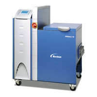
Nordson VersaBlue VT Manual (272 pages)
Melters
Brand:
Nordson
| Category:
Industrial Equipment
| Size: 3.7 MB
Table of Contents
Table of Contents
3
Nordson International
13
Europe
13
Distributors in Eastern & Southern Europe
13
Outside Europe
14
Africa / Middle East
14
Asia / Australia / Latin America
14
China
14
Japan
14
North America
14
Safety
15
Safety Alert Symbols
15
Responsibilities of the Equipment Owner
16
Safety Information
16
Instructions, Requirements, and Standards
16
User Qualifications
17
Applicable Industry Safety Practices
17
Intended Use of the Equipment
17
Instructions and Safety Messages
18
Installation Practices
18
Operating Practices
18
Maintenance and Repair Practices
19
Equipment Safety Information
19
Equipment Shutdown
20
Relieving System Hydraulic Pressure
20
De-Energizing the System
20
Disabling the Applicators
20
General Safety Warnings and Cautions
21
Other Safety Precautions
24
First Aid
24
Safety Labels and Tags
25
Electrostatic Discharge
27
Damage to Electronic Components
27
Personal Injury and Risk of Fire
27
Introduction
29
Intended Use
29
Area of Use (EMC)
29
Operating Restrictions
29
Unintended Use - Examples
29
Residual Risks
30
Note on Manual
30
Other Sources of Information
30
User's Guide
30
Product Resource Disc
30
Definition of Terms
31
Melter Type VA
31
Melter Type VT
31
Interface Standard I/O
31
Interface Key-To-Line
31
Application Head (Gun) = Applicator
31
Residual Current Device (RCD)
31
Symbols
32
Melter Description
33
Illustration
33
Safety Valve Plate
34
Tank Isolation Valve
34
Safety Valve
34
Tank
34
Pressure Control Valve
34
Material Flow
35
Labeling with Two Pumps
35
Electrical Cabinet
36
Level Display, Level Control / Overflow Protection (Option)
37
Pressure Display / Pressure Control (Options)
38
Pressure Display
38
Pressure Control
38
ID Plate
39
Installation
42
Lifting (Unpacked Melter)
42
Installation Requirements
42
Required Space
42
Melters with Transformer
43
Exhausting Material Vapors
43
Screwing on Light Tower (Option)
44
Installation Personnel's Experience
44
Electrical Connections
45
Observe When Using Residual Current Circuit Breakers
45
Laying Cable
45
Labels
45
Operating Voltage
45
Power Supply
46
Mains Filter
46
Installing Kit (Accessory)
46
Connecting Hose
47
Connecting Electrically
47
Connecting
47
Second Open-End Wrench
47
Disconnecting
48
Relieving Adhesive Pressure
48
Installing Applicator
49
Conditioning Compressed Air for Applicator Control Modules
49
Connecting Filling Valve (Option)
49
Key-To-Line: Selecting Line Speed Voltage or Line Speed Current on I/O Board
50
Interface Assignment
51
Interface Standard I/O
51
General Notes
51
Interface Key-To-Line
53
One Line Speed Signal Input for All Motors (XS5)
53
Separate Line Speed Signal Inputs (XS5.1, XS5.2)
53
Interface Level Control
54
Pneumatic Connections
55
Pneumatic Pressure Control / Bypass Control
55
Required Air Quality
55
Setting Pressures
55
Interface Assignment XS4: Automatic Pneumatic Pressure Control
56
Interface Assignment XS4: Bypass Control
57
Inert Gas
58
Condensate Disposal When Dry Air Is Used as Inert Gas
58
Light Tower
59
Installing Kit (Accessory)
59
Casters
60
Installing Kit (Accessory)
60
Air Relief Valve (Accessory)
61
Retrofitting Pressure Sensors
61
Retrofitting a Temperature Control Board
61
IPC Webserver
61
Removing Melter
61
Disposing of Melter
61
Operation
63
General Information
63
Channel Numbers
63
On the Control Panel
63
On the Field Bus
64
Transparent Keys
64
Keys with and Without Indication Lamp
64
Meaning of Colors
64
Description of Symbols
65
Standard Symbols of Temperature Channels
65
Input Window
66
Screen Replacing Motor Controller
66
Status Display
67
Initial Startup
68
Purging Melter
68
Control Panel Settings
69
Standard I/O: Observe for Edge-Controlled Signals (Example)
70
Note on Recipes
73
After the First Day
73
Control Panel - Overview
75
Working with Application Groups and Numbering of Temperature Channels
80
Filling Tank
83
Manually
83
Level Display and Control (Options)
84
Automatic Tank Filling
84
Maximum Level
84
Recommended Temperature Setpoints
85
Heatup Guided by Reference Channel
86
Undertemperature Interlock
87
Motor Startup Protection
87
Acknowledging Startup Protection
87
Daily Startup
88
Daily Switchoff
89
Switching off in an Emergency
89
Control Panel of the Industrial PC (IPC)
90
Melter Modes - Overview
90
Screen Saver
91
Starting Screen
91
Temperature Parameters
92
Important
92
Example: Increase Setpoint Temperature
93
Parameters (Screen 1: Alarm Values)
94
Graphic Presentation of Temperature Parameters
96
Monitoring of Heatup and Cooling
97
Parameters (Screen 2: Activate Channel, Mode, Controlled System Heating Rate)
99
Parameters (Screen 3)
100
Melter
101
Entering/Exiting Standby
101
Switching On/Off All Motors (Collective Enable)
101
Switching On/Off Heaters
102
Switching On/Off Seven-Day Clock
102
Activate Password Protection
102
Alarm Log
103
Information (Melter and Control System)
104
Working with Application Groups
105
Application Groups Setup
105
Setup (Screen 1: Seven-Day Clock, Standby, Inert Gas, Changing Language, Recipes, Level)
108
Important When Using the Seven-Day Clock (Example of a Schedule)
109
Setup (Screen 2: E.g. Units, Ready Delay Time, Password, Service Interval, Field Bus)
114
Control Modes
120
Setup (Screen 3: E.g. Restore Default Settings, Assign New Pressure Sensor)
124
Example: Setting IP Addresses in a Network
125
Motor
128
Switching On/Off Motor (Individual Enable)
128
Selecting Key-To-Line or Manual Mode
128
Parameters (Screen 1: Type of Motor Enable, Adaptation to Parent Machine)
130
Parameters (Screen 2: Key-To-Line)
131
Parameters (Screen 3: Motor off Delay, Threshold Switch)
132
Parameters (Screen 4: Pressure Alarms, Switching between Speed / Pressure Control)
133
Pressure Sensor a / Pressure Sensor B
134
Pressure Sensor C
135
Speed Control - Manual Mode
136
Example: Increase Pump Speed Setpoint
136
Speed Control - Key-To-Line
137
Pressure Control - Manual Mode
138
Pressure Control - Key-To-Line
138
PID Pressure Control Parameters
139
Parameters (Screen 5: Pressure Build-Up Feature)
140
Settings Record
141
Operation Via the IPC Webserver
143
Webserver Login from the Customer's Windows®7 Operating System
143
Setting up Connection between the Server and the Client
144
Connecting Ethernet Cable
144
Calling up Melter (Versaweb)
145
Upload and Download of Customer Recipes
146
Download (Copying Recipe from Memory Board to PC)
146
Upload (Copying and Loading Recipe from PC to New Memory Board)
147
Upload with Software Versions < V5.00.000
148
Maintenance
149
Risk of Burns
149
Relieving Adhesive Pressure
149
Important When Using Cleaning Agents
149
Processing Materials
150
Preventive Maintenance
150
External Cleaning
152
Control Panel
152
Visual Inspection for External Damage
153
Safety and Function Tests
153
Detaching Protective Panels
153
Detaching Insulation Blanket
153
Important Regarding Hooks (Insulation Blanket Support)
154
Fan and Air Filter
154
Gear Pump
155
Checking for Leakage
155
Retighten Gland
155
Replacing Pump Shaft Seal
155
Retightening Fixing Screws
155
Motor
156
Gear Box
156
Selecting Lubricant
156
Lubricants
156
Lubricant Changing Interval
156
Capacity
156
Changing Lubricant
157
Pressure Control Valve
158
Installing Service Kit
158
Important for Mechanical Pressure Control Valve
159
Filter Cartridge
160
Replacing Filter Cartridge
160
Removing Filter Cartridge
160
Installing Filter Cartridge
161
Relieving Air with Air Relief Valve
161
Cleaning Filter Cartridge (until Week 17/2012)
162
Assembling Filter Cartridge
162
Cleaning Filter Cartridge (Week 17/2012 and Later)
163
Assembling Filter Cartridge
163
Filter Cartridge: Installing Service Kit
164
Tank
165
Draining Material
165
Cleaning Tank by Hand
165
Retightening Fixing Screws
165
Safety Valve Plate
166
Installing Service Kit
166
Tank Isolation Valve
167
Installing Service Kit
167
Safety Valve
168
Changing Type of Material
168
Purging with Cleaning Agent
168
Pressure Sensor
169
Cleaning Adhesive Bore
169
Cleaning Separating Membrane
169
Screwing in
169
Inserting/Extracting with Brass Washer
170
Filling Valve
171
Replace Control Module
171
Safety Valve for Pneumatics
172
Performance Check
172
Maintenance Record Form
173
Troubleshooting
175
Helpful Tips
175
Alarm Number, Alarm Text and Optional Light Tower
176
Triggering and Resetting Alarms
180
Graphic Presentation of Temperature Parameters
180
Undertemperature and Overtemperature - Warning
181
Undertemperature Warning Triggered
181
Overtemperature Warning Triggered
181
Undertemperature and Overtemperature - Fault
182
Undertemperature Fault Triggered
182
Overtemperature Fault Triggered
182
Overtemperature - Shutdown
183
Software-Triggered
183
Shutdown by Thermostats
183
Tank Thermostat
183
Transformer Thermostat
183
Underpressure - Warning
184
Underpressure Warning Triggered
184
Overpressure - Warning - / Overpressure - Fault
185
Overpressure Warning Triggered
185
Overpressure Fault Triggered
185
Temperature Sensor - Fault
186
Short-Circuit-Triggered
186
Triggered by Broken Sensor or Open Sensor Input
186
Level (Variable Measuring Points)
186
Warning Tank Overfilled
186
Warning Tank Level Low
186
Fault Tank Empty
186
Level (Fixed Measuring Points - 5-Point Sensor)
187
Warning Tank Overfilled
187
Warning Tank Level Low
187
Fault Tank Empty
187
Fault Level Sensor Defective
187
Fault Level Sensor Failure
187
Troubleshooting Tables
188
Melter Not Functioning
188
One Channel Does Not Heat
188
No Line Speed Signal (Voltage / Current / Frequency)
189
Control Panel Does Not Function
189
No Material (Motor Does Not Rotate)
190
No Material (Motor Rotating)
192
Too Little Material or Irregular Feeding
192
Material Pressure too High
193
Material Pressure too Low
193
Incorrect Motor Rotation in Key-To-Line Mode
193
Material Residue in Tank
194
Material Hardens in Tank
194
Others
195
Filling Valve (Option)
196
Leds and Plugs of I/O Board
196
Frequency Input
196
Analog Inputs
197
Digital Inputs/Outputs (Leds)
197
Leds of Temperature Control Board
199
Leds of Motor Controller
200
LED of Overflow Protection Evaluator
200
LED of Proportional Valve
200
Leds of 5-Point Sensor Evaluator
201
Leds of IPC
202
Checking Transmitted Field Bus Data
203
Repair
205
Observe before Performing Repairs
205
After Repair
205
Control Panel
206
Detaching Control Panel
206
Replacing Memory Board
207
Installing/Replacing the Communication Assembly
208
Important
208
Replacing Motor Controller
210
CAN Bus Terminating Resistor
210
On the Control Panel: Allocating Replaced Motor Controllers (MC) to Their Motors
210
Attaching Shielding Plate (EMC)
212
Retrofitting First Pressure Sensor (Electrical)
213
Replacing Pressure Sensor
213
Information on T-Tap and CAN Bus Cables with Hexagon Nut
213
CAN Bus Terminating Resistor
214
Procedure
214
Replacing Gear Pump
215
Installing Service Kit
215
Tank Isolation Valve
215
Detaching Gear Pump
215
Attaching Gear Pump
216
Important Regarding Coupling
217
Replacing Variseal
218
Assembly Tool
218
Replacing Motor
219
Aligning Motor
220
Replacing Safety Valve
221
Installing Service Kit
221
Replacing Filter Cartridge
222
Observe When Performing Work Behind Electrical Equipment Cover
222
Replacing Thermostat
222
Replacing Heater Connection Insulation
223
Replacing Temperature Sensor
224
Installing Service Kit
224
Replacing I/O Board, Temperature Control Board
225
Setting ni 120 or Pt 100
226
Switching Bus Terminating Resistor ON/OFF
226
Setting DIP Switch S3
226
Replacing Level Evaluator (Option) of Analog Sensor
227
Important Notes
227
Calibrating
228
Prerequisites
228
Replacing Overflow Protection Evaluator (Option)
229
Important Notes
229
Calibrating
230
Prerequisites
230
Sensor Break
230
Limit Switching Points
230
Replacing 5-Point Sensor Evaluator (Option)
231
Important Notes
231
Calibrating
232
Prerequisites
232
Replacing Coupling Component (Option: Separate Line Speed Voltage)
233
Parts
235
How to Use Illustrated Parts List
235
Fasteners
235
Component Designation
235
Special Models
236
Software Configuration Code for Special Models
236
Technical Data
237
General Data
237
Temperatures
238
Electrical Data
238
Max. Melter Load (Without Accessories)
239
Max. Load (Accessories)
239
Max. Load (Accessories) - 1-Phase V12
239
Melter Fuse Protection
239
Mechanical Data
240
Options and Accessories
241
Accessories
244
Password
245
Control Panel P/N 207023 and P/N 207850 (First Generation
249
Validity
249
Visible Distinguishing Features
249
Save Recipe
249
Troubleshooting
250
From Communication Data List
250
Control Panel Does Not Function
251
Control Panel
251
Detaching Control Panel
252
Replacing Battery
253
Replacing Memory Board
253
Parts
254
General Instructions Regarding Working with Application Materials
255
Definition of Terms
255
Manufacturer Information
255
Liability
255
Risk of Burns
255
Vapors and Gases
256
Substrate
256
Processing Temperature
256
Glossary
257
Advertisement
Advertisement
Related Products
Nordson VersaBlue VB Series
Nordson VersaBlue VX Series
Nordson VersaBlue VY Series
Nordson VersaBlue VZ Series
Nordson VersaBlue VD Series
Nordson VersaBlue VC Series
Nordson VersaBlue VE Series
Nordson VersaBlue VW Series
Nordson VersaBlue VA
Nordson VersaBlue VE100
Nordson Categories
Paint Sprayer
Industrial Equipment
Dispenser
Water Pump
Controller
More Nordson Manuals
Login
Sign In
OR
Sign in with Facebook
Sign in with Google
Upload manual
Upload from disk
Upload from URL