Sign In
Upload
Manuals
Brands
nord Manuals
Engine
6052902/1915
nord 6052902/1915 Manuals
Manuals and User Guides for nord 6052902/1915. We have
1
nord 6052902/1915 manual available for free PDF download: Manual With Installation Instructions
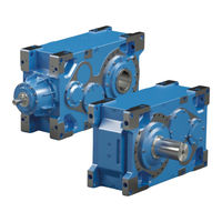
nord 6052902/1915 Manual With Installation Instructions (128 pages)
Industrial gear units
Brand:
nord
| Category:
Engine
| Size: 4 MB
Table of Contents
Table 1: Version List B 1050
5
Table of Contents
8
Safety Information
13
Intended Use
13
Do Not Make any Modifications
13
Performing Inspection and Maintenance Work
13
Personnel Qualification
13
Safety for Particular Activities
14
Check for Transport Damage
14
Safety Information for Installation and Maintenance
14
Hazards
14
Hazards When Lifting
14
Hazards Due to Rotating Parts
14
Danger on Entry
15
Hazards Due to High or Low Temperatures
15
Hazards Due to Lubricants and Other Substances
15
Hazards Due to Noise
15
Hazards Due to Pressurised Coolants
15
Description of Gear Units
16
Type Designations and Gear Unit Types
16
Table 2: Type Designations and Gear Unit Types
16
Figure 1: MAXXDRIVE XT 2-Stage Helical Bevel Gear Unit
17
Table 3: Versions and Options
19
Name Plate
20
Figure 2: Name Plate
20
Transport, Storage, Assembly
21
Transporting the Gear Unit
21
Transport of Standard Gear Units
22
Figure 3: Transport of Standard Gear Unit
22
Transport of Gear Units with Motor Adapter
23
Figure 4: Transport of Gear Units with Motor Adapter
23
Transport of Gear Units with Auxiliary Drives or First Stage Gear Units (Option: WG, WX)
24
Figure 5: Transport of Gear Units with Auxiliary Drives or First Stage Gear Units
24
Transport of Gear Units with V-Belt Drives
25
Figure 6: Transport of Gear Units with V-Belt Drives
25
Transport of Agitator Version Gear Units
26
Figure 7: Transport of Agitator Version Gear Units
26
Transport of Gear Unit with Motor Swing Base or Base Frame
27
Figure 8: Transport of Gear Unit with Motor Swing Base or Base Frame
27
Storage and Downtimes
28
General Measures
28
Storage and Downtimes in Excess of 3 Months
28
Storage and Downtimes in Excess of 9 Months
28
Preparing for Installation
29
Check for Damages
29
Remove Corrosion Protection Agents
29
Check Rotational Direction
30
Check Ambient Conditions
30
Installing the Oil Reservoir Tank (Option OT)
30
Installing the Gear Unit
30
Installation of a Hub on Solid Shaft (Option: V, L)
31
Figure 9: Example of a Simple Pulling Device
31
Figure 10: Permissible Application of Force to Drive and Driven Shafts
32
Assembly of Gear Unit with Hollow Shaft (Option: A, EA)
33
Figure 11: Applying Lubricant to the Shaft and the Hub
33
Fitting a Hollow Shaft with Fastening Element (Option: B)
34
Figure 12: Assembly and Disassembly of the Fastening Element (Schematic Diagram)
34
Fitting a Hollow Shaft with Shrink Disc (Option: S)
35
Figure 13: Fastening Element (Example)
35
Figure 14: Machine Shaft Assembly for Special Hollow Shafts with Shrink Discs
36
Figure 15: Fitted Shrink Disc
37
Fitting a Hollow Shaft with GRIPMAXX™ (Option: M)
38
Figure 16: GRIPMAXX™, Exploded Diagram
38
Table 4: Permissible Machine Shaft Tolerances
39
Installing a Flange Version Gear Unit (Option: F, FK, VL2/3/4/5, KL2/3/4)
41
Agitator Version (Option: VL2, KL2)
41
Agitator Version with Drywell (Option: VL3, KL3)
41
Figure 17: VL2 Option
41
Agitator Version with True Drywell (Option: VL4, KL4)
42
Extruder Flange Version (Option: VL5)
42
Figure 18: Option VL3/KL3 and VL4/KL4
42
Agitator Version with True Drywell and Foot Mounting (Option: VL6, KL6)
43
Figure 19: Option VL6/KL6
43
True Drywell Version Gear Units (Option: VL4, KL4, VL6, KL6, DRY)
44
Figure 20: Schematic Diagram (Option: DRY)
44
Motor Base Frame (Option: MF)
45
Motor Swing Base (Option: MS)
46
Motor Mount (Option: MT)
47
Installing the Belt Drive
47
Figure 21: V-Belt Pulley (Disassembled/Assembled)
48
Figure 22: Axle Alignment (Belt Drives)
49
Installing the Cover Cap, Air Baffle (Option: H, H66, FAN, MF
50
Fitting a Standard Motor (Option: IEC, NEMA)
50
Table 5: IEC and NEMA Motor Weights
50
Figure 23: Centre of Gravity of Motor
51
Table 6: Transnorm Motor Weights
51
Installing the Drive Coupling
52
Dog Coupling
52
Turbo Coupling
52
Figure 24: Fitting the Coupling to the Motor Shaft
52
Dog Coupling
53
Installing the Output Coupling
53
Figure 25: Fusible Plug with Separate Mechanical Switch
53
Installation of the Internal Cooling System (Option: CC)
54
Installation of an External Cooling System (Option: CS1-X, CS2-X)
55
Figure 26: Cooling Cover with Cooling Coil Fitted (Schematic Diagram)
55
Installing a Fan (Option: FAN-A, FAN-R)
56
Figure 27: Industrial Gear Unit with CS1-X and CS2-X Cooling Systems
56
Figure 28: Hydraulic Plan of Industrial Gear Units with CS1-X and CS2-X Cooling Systems
56
Installation of the Lubricant Circulation (Option: LC, LCX)
57
Gear Unit Monitoring Sensors (Option: MO)
57
Installing the Torque Arm (Option: D, ED, MS)
57
Figure 29: Permissible Installation Tolerances of the Torque Arm (Option D and ED) (Schematic Diagram)
58
Connecting the Oil Heater (Option: OH)
59
Adjusting the Brake
59
Automatic Lining Wear Correction (Option: LWC)
59
Limit Switch to Indicate the Brake Lining Wear (Option SLW)
60
Connecting the NC/NO Contacts (Option: SO/SC)
60
Manual Release and Manual Release with Limit Switch (Option: MR, Option: MRS)
60
Subsequent Painting
60
Commissioning
61
Checking the Oil Level
61
Activating the Vent
61
Table 7: Oil Spaces as Delivered
61
Taconite Seal/Labyrinth Seal
62
Figure 30: Activation of the Pressure Vent
62
Figure 31: Checking a Taconite Seal
62
Heated Output Hollow Shaft
63
Lubricant Circulation (Option: LC, LCX)
63
Gear Unit Cooling with Fan (Option: FAN-A, FAN-R)
63
Cooling Coil (Option: CC)
65
External Cooling System (Option: CS1-X, CS2-X)
66
Oil / Water Cooler (Option: CS1-X)
66
Oil / Air Coolers (Option: CS2-X)
67
Oil Heater (Option: OH)
67
Temperature Monitoring (Option: PT100)
67
Backstop/Auxiliary Drive (Option: R, WX)
68
Figure 32: Industrial Gear Unit with Back Stop (Schematic Diagram)
69
Table 8: Back Stop Lift-Off Speeds SK 5..07 - SK 10..07
70
Test Run
71
Table 9: Back Stop Lift-Off Speeds SK 11..07 - SK 15..07
71
Table 10: Back Stop Lift-Off Speeds SK 5..17 - SK 11..17
71
Checklist
72
Obligatory
72
Table 11: Obligatory Checklist for Commissioning
72
Optional
73
Table 12: Optional Checklist for Commissioning
73
Service and Maintenance
74
Inspection and Maintenance Intervals
74
Table 13: Inspection and Maintenance Intervals
75
Service and Maintenance Work
76
Visual Inspection for Leaks
76
Check for Running Noises
76
Check Fan and Spaces between the Ribs (Maxxdrie XT) (Option: FAN-A, FAN-R)
76
Cleaning the Heat Exchanger (Option: CS2-X)
77
Oil Level
77
Oil Level Screw
78
Oil Inspection Glass/Oil Level Glass (Option: OSG), Oil Level Indicator (Option: OST)
78
Oil Dipstick (Option: PS)
78
Figure 33: Checking the Oil Level with a Dipstick
78
Figure 34: Checking the Oil Level with an Oil Dip-Stick
78
Oil Level Tanks (Option: OT)
79
Checking the Leak Indicator (Option: VL3, KL3 with Drywell)
79
Seal Adapter for Agitators (Option: SAFOMI)
80
Figure 35: Illustration Air Space
80
Visual Inspection of the Rubber Elements of the Elastic Torque Arm (Option: ED)
82
Visual Inspection of Cables
82
Piping (Option: LC, LCX, OT)
82
Hose Lines (Option: LC, LCX, CS1-X, CS2-X, OT)
82
Oil Filter (Option: CS1-X, CS2-X, LC/LCX)
82
Remove Dust
82
Oil Change
83
Checking the Cooling Coil for Deposits (Option: CC)
84
Cleaning or Replacing the Vent
84
Vent Filter (Option: FV)
84
Cellulose Filter (Option: EF)
84
Figure 36: Vent Filter (Option FV)
84
Figure 37: Cellulose Filter (Option EF)
84
Drying Agent Filter / Wet Air Filter (Option: DB)
85
Figure 38: Drying Agent Filter, Example Version
85
Figure 39: Installing the Drying Agent Filter
85
Replacing the Shaft Sealing Ring
86
Re-Lubrication of Bearings in the Gear Unit
86
Figure 40: MSS7 Seal
86
Re-Lubricating the Bearing in the Output Flange (Option: VL2/3/4/6, KL2/3/4/6)
87
Re-Greasing the Taconite Seal
88
Figure 41: Re-Grease Taconite Seal
88
Table 14: Grease Quantities for Re-Greasing the Lower Output Shaft Bearing
88
Checking V-Belts (Belt Drives)
89
Inspection Cover
89
Figure 42: Examples of Inspection Covers
90
General Overhaul
91
Disposal
92
Table 15: Materials
92
Appendix
93
Versions and Mounting Position
93
Parallel Gear Units
93
Figure 43: Helical Gear Unit Installation Positions with Standard Mounting Surface
93
Helical Bevel Gear Unit
94
Standard Positions of the Oil Drain, Vent and Oil Level
94
Figure 44: Bevel Gear Unit Installation Positions with Standard Mounting Surface
94
Table 16: Position of Housing Options on Oil Screw Holes (Standard Installation Positions)
96
Figure 45: Numbering of Oil Screw Holes on SK 5207 - SK 10507
102
Figure 46: Numbering of Oil Screw Holes on SK 11207 - SK 15507
108
Figure 47: Numbering of Oil Screw Holes on SK 5217 - SK 11217
112
Lubricants
113
Roller Bearing Greases
113
Table 17: Roller Bearing Greases
113
Gear Oils
114
Table 18: Lubricant Oil Table
115
Minimum Starting Temperatures
116
Table 19: Minimum Starting Temperatures for Mineral Oils (Guideline Values for the Ambient Temperature)
116
Table 20: Minimum Starting Temperatures for Synthetic Oils (Guideline Values for the Ambient Temperature)
116
Lubricant Quantities
117
Screw Tightening Torques
118
Tolerances for Bolting Surfaces
118
Table 21: Screw Tightening Torques
118
Troubleshooting
119
Table 22: Overview of Malfunctions
120
Leakage and Leak-Tightness
121
Table 23: Definition of Leaks According to DIN 3761
121
Noise Emissions
122
Repair Information
122
Repairs
122
Internet Information
122
Warranty
122
Abbreviations
123
Advertisement
Advertisement
Related Products
nord 6052902/0213
nord 6052902/3814
nord 6052902/0916
nord 6052902/1817
nord 6052902/1819
nord 6052902/4419
nord 6052902/4620
nord 6052902/3921
nord 6051302
nord Electro 6
nord Categories
Industrial Equipment
Engine
Musical Instrument
Inverter
DC Drives
More nord Manuals
Login
Sign In
OR
Sign in with Facebook
Sign in with Google
Upload manual
Upload from disk
Upload from URL