NORCOLD N84 - Manuals
Manuals and User Guides for NORCOLD N84 -. We have 4 NORCOLD N84 - manuals available for free PDF download: Service Manual, Installation Manual, Parts List
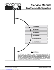
Norcold N84 - Service Manual (77 pages)
Gas/Electric Refrigerators
Brand: Norcold
|
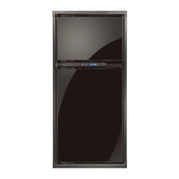
Category: Refrigerator
|
Size: 4.13 MB
Table of Contents
Advertisement
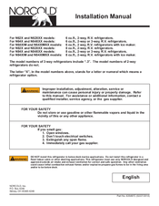
Norcold N84 - Installation Manual (48 pages)
6 cu.ft., 2-3-way R.V. refrigerators
Brand: Norcold
|
Category: Refrigerator
|
Size: 6.54 MB
Table of Contents
Norcold N84 - Installation Manual (20 pages)
Thetford N621: Install Guide
Brand: Norcold
|
Category: Refrigerator
|
Size: 0.94 MB
Table of Contents
Advertisement
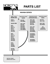
NORCOLD N84 - Parts List (13 pages)
Brand: NORCOLD
|
Category: Refrigerator
|
Size: 0.73 MB
Advertisement