Nilfisk-Advance 9087350020 Manuals
Manuals and User Guides for Nilfisk-Advance 9087350020. We have 3 Nilfisk-Advance 9087350020 manuals available for free PDF download: Service Manual
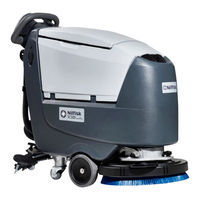
Nilfisk-Advance 9087350020 Service Manual (188 pages)
Brand: Nilfisk-Advance
|
Category: Floor Machine
|
Size: 21 MB
Table of Contents
Advertisement
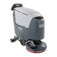
Nilfisk-Advance 9087350020 Service Manual (130 pages)
Brand: Nilfisk-Advance
|
Category: Scrubber
|
Size: 23 MB
Table of Contents
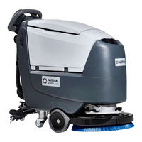
Nilfisk-Advance 9087350020 Service Manual (100 pages)
Brand: Nilfisk-Advance
|
Category: Scrubber
|
Size: 15 MB
Table of Contents
Advertisement