Sign In
Upload
Manuals
Brands
Nilfisk-Advance Manuals
Floor Machine
56107507
Nilfisk-Advance 56107507 Manuals
Manuals and User Guides for Nilfisk-Advance 56107507. We have
1
Nilfisk-Advance 56107507 manual available for free PDF download: Service Manual
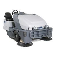
Nilfisk-Advance 56107507 Service Manual (207 pages)
Brand:
Nilfisk-Advance
| Category:
Floor Machine
| Size: 17.08 MB
Table of Contents
Service Manual
1
Table of Contents
2
General Information
9
General Machine Description
9
Service Manual Purpose and Application
9
Other Reference Manuals and Information Sources
9
Nilfisk-Advance Publications
9
Engine Manufacturers' Technical Manuals
9
Introduction
9
Parts and Service
10
Name Plate
10
General Safety Instructions
11
Hopper Safety Support
12
Jacking the Machine
13
Transporting the Machine
14
Towing or Pushing a Disabled Machine
15
Technical Specifications
16
Fastener Torque Specifications
18
Maintenance
19
Maintenance Schedule
19
After Use
19
To Shut down the Diesel / Gasoline Engine
20
To Shut down the Propane Engine
20
Important Machine Lubrication
20
Engine Coolant
20
Engine Oil - Gasoline / Petrol & Lpg
21
Engine Oil - Diesel
21
Engine Air Filter
22
Engine Maintenance (150 Hours)
22
Hydraulic Oil
22
Hopper Dust Control Filter (Panel Filter)
23
To Remove the Hopper Dust Control Filter
23
Method "A
23
Method "B
23
Method "C
23
SW8000 PM Checklist
24
Know Your Machine
26
Operator's Compartment
28
Control Panel
29
Control System
30
Functional Description
30
Control Panel
30
Main Machine Controller
33
Component Locations
34
Main Machine Controller Programming
35
Hydrostatic Neutral Position and Dead-Band
35
Recall of Stored Fault Codes
35
Automatic Shaker Operation
36
Troubleshooting
36
Main Controller Error Codes
36
Removal and Installation
38
Main Control Board
38
Specifications
39
Sample Shop Voltage Measurements
39
Dust Control System
41
Functional Description
41
Dustguard™ Spray System (Optional)
41
Circuit Description
41
Dust Control Vacuum System
41
Simplified Schematic Diagram
42
Component Locations
43
Maintenance and Adjustment
44
Dustguard Spray Nozzle Cleaning
44
Dust Control Filter Cleaning
44
Troubleshooting
45
Dust Control Vacuum Motor will Not Run
45
Dust Control Vacuum Motor will Not Shut off
46
Shaker Motor will Not Run
47
Misting Pump will Not Run
48
Specifications
49
Electrical System
50
Functional Description
50
Overview
50
Gauge Panel Assembly
50
Circuit Breaker Panel Assembly
51
Wire Identification
52
Rotary Sensor
52
Seat Switch Circuit Description
53
Component Locations
54
Battery
54
Instrument Panel Assembly
55
Circuit Breakers
55
SPDT Relays
56
K11 Seat Relay Coil and K12 Timer Relay (Seat Switch Option Only)
56
S22 Brake Switch (Seat Switch Option Only)
57
Rotary Sensor
57
Electrical Connectors
58
Component to Connector ID Look-Up Table
58
Component to Relay ID Look-Up Table
59
Connector Pin-Out Assignments
59
Troubleshooting
66
Specifications
66
Wiring Diagrams, P/N 56382530, Rev. D
67
Wiring Diagram, Kubota Gasoline Engine, P/N 56107658, Rev
70
Wiring Diagram, Kubota LP Engine, P/N 56107659, Rev
71
Wiring Harness Diagrams, P/N 56382531 Rev. D
72
Engine System, Diesel
75
Functional Description
75
Overview
75
Engine Description
75
Manufacturers' Technical Literature
76
Engine Starter Circuit
76
Starter Circuit Description
76
Engine Protection - Low Oil Pressure Shutdown
77
Engine Speed Control
77
Glow Plug Control
78
Component Locations
79
Maintenance and Adjustments
81
Maintenance Schedule
81
Engine Oil
82
Engine Coolant
82
Checking Engine Coolant
82
Replacing Engine Coolant
83
Engine Air Filter Maintenance
84
Replacing the Fuel Filter
84
Bleeding the Fuel System
85
Troubleshooting
88
General Troubleshooting
88
Engine Overheating Problems
89
Loss of Oil Pressure
89
APECS 3000 Controller Fault Codes
89
Compression Test
90
Specifications
92
Special Tools
93
Engine System, Gasoline/Lpg
95
Functional Description
95
Overview
95
Engine Description
95
Kubota 1 6L Gasoline Fuel System Description
95
Kubota 1 6L LPG Fuel System Description
95
Engine Starter Circuit Description
96
Engine Protection - High Temperature
97
Engine Protection - Low Oil Pressure Shutdown
97
Engine Speed Control
97
Component Locations
98
LPG and Gasoline Engine Common Electrical Components
98
LPG ONLY Engine Electrical and Fuel Components
101
Gasoline (Petrol) ONLY Engine Electrical and Fuel Components
102
Maintenance and Adjustments
103
Maintenance Schedule
103
Engine Oil
104
Checking Engine Coolant
104
Engine Coolant
104
Replacing Engine Coolant
105
Engine Air Filter Maintenance
106
Troubleshooting
106
General Troubleshooting
106
Engine Overheating Problems
107
Shop Measurements
109
Engine Vacuum
109
Special Tools
110
Hopper System
111
Functional Description
111
Overview
111
Hopper
111
Hopper Door
112
Hopper Hydraulic System
113
Hopper System Wiring Diagram
114
Hopper System Circuit Description
115
Hopper System Hydraulic Diagrams
116
Hopper Down, Hopper Door Closed
116
Raise Hopper
117
Lower Hopper
118
Open Hopper Door
119
Close Hopper Door
120
Component Locations
121
Hopper
121
Hopper Interlock Switch
121
Hopper Lift Cylinder
122
Hopper Prop Rod
122
Hopper Door Cylinder
123
Hydraulic Manifold Assembly and Solenoid Valves
123
Troubleshooting
124
Specifications
126
Hydraulic System
127
Functional Description
127
Overview
127
Hydraulic Pumps
128
Hydraulic Manifold Assembly
128
Electrical Schematic
129
Electrical Circuit Description
129
Component Locations
130
Hydraulic Piston and Gear Pumps
130
Hydraulic Manifold Assembly
130
Hydraulic Oil Reservoir
131
Oil Filter
131
Oil Cooler
132
Maintenance and Adjustments
132
To Check the Hydraulic Oil Level
132
To Change the Hydraulic Oil Filter
133
To Clean the Hydraulic Oil Cooler
133
Troubleshooting
134
General Information Regarding Checking Hydraulic Pressures
134
General Troubleshooting
134
Checking the Gear Pump Pressure
135
Checking the Piston Pump Pressure
136
Hydraulic Truth Table
136
Specifications
137
General Specifications
137
Hydraulic Manifold Assembly
138
Special Tools
139
Hydraulic Schematic, 56507055, Rev. L
140
Options and Accessories
141
SW8000 Deluxe Cab Options
151
Technical Specifications
151
Cab Controls
152
Heating System Components
153
Air Conditioning System Components
154
Maintenance
155
Maintenance Schedule
155
To Clean and Replace the Cab Filter
155
Heating System
156
General System Overview
156
Electrical Circuit Overview
156
Heater Blower Motor
156
Heater Temperature Control
156
Electrical Troubleshooting
157
To Troubleshoot the Heater Temperature Control
159
To Eliminate Air Locks from the Cooling System
160
Cooling System Vacuum Filler
160
Purge the Heater Circuit
160
Air Conditioning System
161
Electrical Circuit Overview
161
General System Overview
161
Condenser Fan, Thermostat, Pressure Switch and Compressor Motor
162
Electrical Troubleshooting
163
Component Troubleshooting
165
Accessory (Gear) Hydraulic Pump
166
Compressor Relay (K10)
166
Binary Pressure Switch (S34)
167
Thermostat (S33)
169
Heating and A/C System Plumbing and Hydraulic Flow Schematic
171
Steering System
172
Functional Description
172
Overview
172
Hydraulic Diagrams
174
Steering Control Unit Description
174
Steering Wheel Stationary
175
Steering Wheel Turned Toward the Right
176
Steering Wheel Turned Toward the Left
177
Steering Wheel Held in Full Right or Left Position
178
Turning the Steering Wheel with the Engine off
179
Component Locations
180
Steering Wheel and Steering Control Unit
180
Steering Cylinder
180
Maintenance
181
Troubleshooting
182
Specifications
182
Sweep System, Main Broom
183
Functional Description
183
Circuit Description
183
Hydraulic Operation
184
Component Locations
185
Maintenance and Adjustment
186
Cleaning and Inspecting the Main Broom
186
Rotate or Replace the Main Broom
186
Inspect and Adjust the Broom Height
187
Inspect Housing Skirts
187
Troubleshooting
188
Main Broom Motor will Not Run
188
Specifications
189
Sweep System, Side Broom
190
Functional Description
190
Circuit Overview
190
Electrical Circuit
191
Hydraulic Circuit, Brooms off
191
Hydraulic Circuit, Brooms on
192
Component Locations
193
Troubleshooting
194
Side Broom Won't Run
194
Side Broom Won't Raise
195
Side Broom Won't Lower
195
Specifications
195
Wheel System, Non-Traction
196
Functional Description
196
Maintenance and Adjustments
196
Troubleshooting
196
Removal and Installation
196
To Remove and Reinstall a Wheel
196
To Remove and Reinstall a Brake and Spindle Assembly
197
Wheel System, Traction
198
Functional Description
198
Overview
198
Piston (Drive) Pump and Drive Motor
198
Foot Pedal Assembly
199
Forward/Reverse Controls
199
Rear Wheel Assembly
200
Electrical Schematic and Circuit Description
200
Hydraulic Diagrams
201
Drive Motor in Neutral
201
Tow Valve in Bypass Position
201
Drive Motor in Forward or Reverse
202
Drive Motor Stalling out
203
Component Locations
204
Piston (Drive) Pump and Tow Valve
204
Drive Motor and Rear Wheel Assembly
204
Foot Pedal Assembly
205
Forward/Reverse Controls
205
Advertisement
Advertisement
Related Products
Nilfisk-Advance 56107501
Nilfisk-Advance 56107503
Nilfisk-Advance 56107505
Nilfisk-Advance 56107509
Nilfisk-Advance 56107511
Nilfisk-Advance 56107512
Nilfisk-Advance 56107513
Nilfisk-Advance 56107514
Nilfisk-Advance 56107515
Nilfisk-Advance 56107517
Nilfisk-Advance Categories
Vacuum Cleaner
Floor Machine
Scrubber
Pressure Washer
Blower
More Nilfisk-Advance Manuals
Login
Sign In
OR
Sign in with Facebook
Sign in with Google
Upload manual
Upload from disk
Upload from URL