Sign In
Upload
Manuals
Brands
NF Manuals
AC Power Distribution
KP3000S
NF KP3000S Programmable Power Source Manuals
Manuals and User Guides for NF KP3000S Programmable Power Source. We have
1
NF KP3000S Programmable Power Source manual available for free PDF download: Instruction Manual
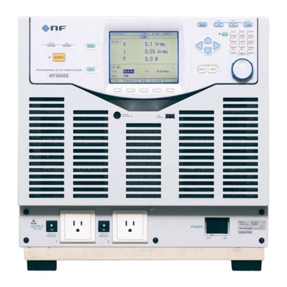
NF KP3000S Instruction Manual (290 pages)
PROGRAMMABLE AC/DC POWER SOURCE
Brand:
NF
| Category:
AC Power Distribution
| Size: 3 MB
Table of Contents
Preface
5
Safety Precautions
6
Table of Contents
9
List of Figures
15
1 Outline
19
Overview
20
Polyphase System Configuration
20
Features
20
2 Preparation before Use
23
Check before Use
24
About Installation Environment
24
Table 2-1 List of Content
24
Table 2-2 Heat Value (Estimate at Power Input 200 V, Rated Output)
24
Figure 2-1 How to Use the Adjuster Foot (Caster Type)
25
Table 2-3 Weight
25
Cautions During Moving and Transportation
26
Grounding and Power Connections
28
Table 2-4 Power Input Terminal
29
Table 2-5 Maximum Input Power/Current and Power Input Cable
29
Output and System Cable Connection
32
Table 2-6 Output Terminals
32
Polyphase System
34
Table 2-7 Outlet List
34
How to Tilt Control Panel
38
Simple Operation Check
39
Calibration
41
3 Basic Operation
43
Component Name
44
Front
44
Figure 3-1 Component Name (Front)(Foot Type)
44
Figure 3-2 Component Name (Front) (When the Outlet Is Selected)(Caster Type)
44
Table 3-1 Component Name (Front)
45
Rear
46
Figure 3-3 Component Name (Rear)(Foot Type)
46
Figure 3-4 Component Name (Rear) (Caster Type)
46
Table 3-2 Component Name (Rear)
47
Control Panel
48
Figure 3-5 Component Name (Control Panel)
48
Table 3-3 Component Name (Control Panel)
48
Power On/Off
49
Before Turning on the Power
49
Power on
50
Screen Display and Operations at Starting up
50
Figure 3-6 the Self Check Screen to be Displayed When Starting the Unit in Other System or in Other Output Phase Mode than before
50
The Settings Loaded after Startup
51
Checking the Rated Power
51
Power off
51
Figure 3-7 the Rated Power Icon
51
Basic Key Operations
52
Changing the Output Function (Continuous Output/Sequence/Simulation)
52
Item Selection
52
Figure 3-8 the Root Menu
52
Using Soft-Keys
53
Figure 3-9 the Example of a Selection Box
53
Figure 3-10 the Example of a Data List Box
53
Figure 3-11 Soft-Key Function
53
Closing Windows
54
Figure 3-12 the Example of the Window with the [Close] Button
54
Figure 3-13 the Example of the Window with the [Ok]/[Cancel] Button
54
Entering Values (Numerical Entry Box)
55
Entering Strings (Character String Entry Box)
55
Figure 3-14 the Numerical Entry Box
55
Figure 3-15 Character String Entry Box
56
Table 3-5 Character String Entry List
56
Using Shortcut Operations (SHIFT Key)
57
Table 3-6 Shortcut Operations
57
Using the Continuous Function
58
Setting the AC/DC Mode and the Signal Source
58
Table 3-7 Description of the AC/DC Mode
58
Table 3-8 the Description of the Signal Source
58
Table 3-9 List of the Selectable Combinations of the AC/DC Mode and the Signal Source
59
Setting the Output Range
61
Table 3-10 the Setting Range Per Output Range
61
Setting Waveforms
62
Setting the Output Voltage (Single-Phase Output)
64
Setting the Output Voltage (Polyphase Output)
65
Setting the Output Frequency
67
Setting the Output On/Off Phase
67
Turning the Output on or off
68
Using the Measurement Function
69
Table 3-11 Main Measurement Functions
69
Switching the Display Format (Rms/Avg/Peak) of the Measured Value
70
Enlarge Display Letters for the Measured Value
72
Figure 3-16 the Normal View (Left) and the Simple View Mode (Right)
72
Clearing the Output Current Peak-Hold Value
74
Switching the Target Phase of Which the Measured Values Are Displayed (Polyphase Output)
76
4 Advanced Operation
79
Using Limiter, Setting Limiter
80
Use Peak Current Limiter
80
Using RMS Current Limiter
82
Using Voltage Setting Range Limit
83
Using Frequency Setting Range Limit
85
About Wattage Limiter
86
Using Sequence Function
87
Basics
87
Table 4-1 Wattage Limiter Value Per Phase
87
Figure 4-1 Step-Control Parameters and Intra-Step Parameters
88
Figure 4-2 Step Behavior
89
Parameters of Sequence Function
90
Table 4-2 Parameters of Sequence Function
90
Figure 4-3 Stop Phase
92
Example of Output Using Sequence Function
93
Process Flow in a Step
93
Figure 4-4 Example of Sequence
93
Table 4-3 Example of Editing Sequence
93
Figure 4-5 Process Flow in Sequence Step
94
Figure 4-6 Branch Operation/Stop Operation
94
Edit a Sequence
95
Load a Sequence
98
Execute a Sequence
102
Save a Sequence
106
Clear/Rename Sequence
110
Set so as the Sequence Function Is Selected at Power-On
114
Sequence Control by External Control
115
Screen Overview
115
Figure 4-7 Sequence Edit View
116
Figure 4-8 Sequence Control View (Output off State)
116
Figure 4-9 Sequence Control View (Output on State/Sequence in Execution)
116
Using Power Fluctuation Testing (Simulation) Function
117
Basics
117
Figure 4-10 Sequence Control View (Output on State/Sequence Stopped)
117
Using Power Fluctuation Testing (Simulation)
117
Simulation Function Parameters
118
Table 4-4 Simulation Function Parameters
118
Function
118
Figure 4-11 Simulation Function Steps
119
Table 4-5 Simulation Function Steps and Settable Step Parameters
119
Output Examples Using Simulation Function
120
Figure 4-12 Voltage Dip Simulation Example
120
Figure 4-13 Voltage Change Simulation Example
121
Table 4-6 Voltage Dip Simulation Edit Example
121
Table 4-7 Voltage Change Simulation Edit Example
121
Process Flow in a Step
122
Editing Simulation
122
Figure 4-14 Process Flow through Simulation Steps
122
Figure 4-15 Stop Operation
122
Loading a Simulation
125
Executing Simulation
128
Saving Simulation
130
Clear/Rename Simulation
134
Set so as the Simulation Function Is Selected at Power-On
138
Simulation Control by External Control
139
Screen Overview
139
Figure 4-16 Simulation Edit View
140
Figure 4-17 Simulation Control View (Output off State, Simulation Stopped)
140
Figure 4-18 Simulation Control View (Output on State, Simulation Running)
140
Measuring Harmonic Current
141
Harmonic Current
141
Figure 4-19 Simulation Control View (Output on State, Simulation Stopped)
141
Figure 4-20 Current Waveform Containing Many Harmonic Components
141
Basics
142
Measured Value Display Method
142
Measuring Inrush Current
143
Inrush Current
143
Figure 4-21 Inrush Current Example
143
Basics
144
Measurement Method
144
Measurement Tips
145
Using Clipped Sine Wave
145
Figure 4-22 Clipped Sine Wave
145
Table 4-8 Different Output Voltage Settings Depending on Clip Depth Setting Method
146
Outputting Arbitrary Waveform
148
Basics
148
Arbitrary Waveform Creation Procedure
149
Arbitrary Waveform Creation Example
149
Transferring Arbitrary Waveform
149
Outputting Arbitrary Waveform
152
Using Memory Function
153
Basic Setting Memory
154
Arbitrary Waveform Memory
161
Sequence Memory
165
Table 4-9 Content Saved in Sequence Memory
165
Simulation Memory
166
Table 4-10 Content Saved in Simulation Memory
166
Using USB Memory Function
167
Figure 4-23 USB Memory Folder Structure
167
Using Monitor Function
168
Using Remote Sensing Function
171
Using AGC Function
173
Using Autocal Function
176
Adjusting DC Offset
180
Table 4-11 Setting Range of DC Offset Adjustment Value
180
Using for Unbalanced Polyphase Output
182
Using as DC Power Supply
184
Setting Voltage Using External DC Input Signal
185
Using External Signal in AC-VCA Mode
185
Using External Signal in DC-VCA Mode
187
Control Using External Control Function
189
Table 4-12 CONTROL I/O Pin Assignment
190
Synchronizing the Output Frequency with the Power Line or the External Signal
194
Amplifying the External Signal Input
196
Turning the Output on or off Rapidly
197
Table 4-13 the Output Terminal Impedance (Reference Values in the Rear Output Terminal)
197
Enabling Automatic Output-On at Power-On
199
Figure 4-24 the Message Window to be Shown before the Automatic Output-On after the
199
Using the Emission CO
200
Calculator
200
Power Unit Energization Setting (Using under the Restricted Rated Power)
202
Power Unit Energization Setting
202
Restricted Rated Power)
202
Key Lock
204
Beep
204
Changing the Background Color and the Contrast of the Screen
205
Of the Screen
205
Restoring to the Factory Default Setting (Reset)
206
Table 4-14 Setting Items to be Reset
206
5 Description of Screen and Menu
211
Screen Configuration
212
Figure 5-1 Component Name (Display Areas on the Screen)
212
Table 5-1 Component Name (Display Areas on the Screen)
212
Status Icon
213
Table 5-2 Status Icons
213
Measured Value Display Items
214
Table 5-3 Measured Value Display Items
214
Output Setting Display Items
215
Table 5-4 Output Setting Display Items
215
Warning and Error Display
215
Menu Composition
216
Menus of the Continuous Function
216
Figure 5-2 Menu Composition
216
Table 5-5 Menus of the Continuous Function
216
Menus of the Sequence Function
217
Table 5-6 Menus of the Sequence Function
217
Menus of the Simulation Function
218
Menus of the Memory Function
218
Table 5-7 Menus of the Simulation Function
218
Table 5-8 Menus of the Memory Function
218
System Menus
219
Table 5-9 System Menus
219
6 Remote Control
221
Communication Interface
222
Usb
222
Rs232
224
Gpib
226
Remote/Local State Switching
228
Remote State
228
Local State
228
7 Options
229
Outlet
230
Casters
230
Application Software
230
Table 7-1 Outlet
230
System Cable (for Polyphase System)
231
Remote Controller
231
Figure 7-1 Remote Controller External View
231
Replacement Air Filter
232
Rack-Mount Adapter
232
Additional Cable
232
Figure 7-2 Front Grills
232
Table 7-2 Rack-Mount Adapter Model Names
232
8 Troubleshooting
233
Error Messages and Error Handling
234
Error Message Screen
234
If an Error Message Is Displayed
234
Figure 8-1 Error Message Screen Example
234
Table 8-1 Description of the Error Message Screen
234
If an Error Occurs Repeatedly
235
Protection Operation Types
236
Error Message List
237
Table 8-2 Error Message List
237
When a Failure Is Suspected
241
Table 8-3 Actions When a Failure Is Suspected
241
9 Maintenance
247
Preface
248
Daily Maintenance
248
Storage, Repackaging, Transportation
250
Checking Firmware Version
250
10 Specifications
253
Output Function
254
Output Range
254
AC/DC Mode
255
Signal Source
256
AC Output
257
DC Output
259
Output Voltage Stability
259
Distortion of Output Voltage Waveform
260
Power Input
260
Withstand Voltage and Insulation Resistance
260
Measurement Function
261
Power Unit Energization Setting
263
Current Limiter
264
Setting Range Limit Function
265
Remote Sensing
266
Agc
266
Autocal (Output Voltage Compensation)
267
Sequence
268
Simulation
269
Clipped Sine Wave
270
Arbitrary Wave
270
External Signal Input
271
External Synchronous Signal Input (Signal Source SYNC Only)
271
Voltage Setting Signal Input (Signal Source VCA Only)
271
External Signal Input (Only EXT and ADD)
272
General Function
272
Memory Function
273
Self-Diagnosis/Protection Function
274
External Control I/O
275
External Interface
276
USB Memory Interface
276
Waveform Monitor Output
277
Safety and EMC
277
Operation Environment
277
Figure 10-1 Range of Ambient Temperature/Humidity
278
Externals, Weight, and Terminal Block
278
Figure 10-2 Outline Dimensional Drawing
280
Outline Dimensional Drawing
280
Advertisement
Advertisement
Related Products
NF KP3000GS
NF KP2000AS
NF DP Series
NF DP015RS
NF DP015S
NF DP020AS
NF DP030D
NF DP030RD
NF DP030RS
NF DP030S
NF Categories
Amplifier
Measuring Instruments
AC Power Distribution
Portable Generator
Power Supply
More NF Manuals
Login
Sign In
OR
Sign in with Facebook
Sign in with Google
Upload manual
Upload from disk
Upload from URL