Table of Contents
Advertisement
Quick Links
Advertisement
Table of Contents

Related Manuals for NF KP3000S

Summary of Contents for NF KP3000S
- Page 1 PROGRAMMABLE AC/DC POWER SOURCE KP3000S INSTRUCTION MANUAL NF Corporation...
- Page 3 DA00030908-004 PROGRAMMABLE AC/DC POWER SOURCE KP3000S INSTRUCTION MANUAL...
-
Page 5: Preface
Preface Thank you for purchasing our Programmable AC/DC Power Source KP3000S. For safe and correct use of the electrical product, please first read "Safety Precautions" on the next page. Alert symbols in this manual This manual uses the following alert symbols. The instructions by these alert symbols shall be carefully obeyed to ensure equipment operator's safety and prevent damage to equipment. -
Page 6: Safety Precautions
Safety Precautions For safe use, ensure to obey the following warnings and considerations. We are not responsible for damage resulting from failure to obey these warnings and considerations. This product is an insulation Class I device (with a protective conductor terminal) complying with the JIS and IEC standards. - Page 7 When this product is used in wet condition, it may cause an electric shock and a fire. If this product is exposed to water, cut the power at the distribution board immediately, and contact NF Corporation or one of our representatives.
- Page 8 Other symbol Chassis This indicates that the terminal (or external conductor for a connector) is connected to the chassis. Request about disposal For environmental preservation, pay attention to the followings when you dispose of this product. The CCFL backlight of the LCD contains mercury. CCFL-LCDs are embedded in early models. ...
-
Page 9: Table Of Contents
Changing the Output Function (Continuous Output/Sequence/Simulation) ..34 3.3.2 Item Selection ....................34 3.3.3 Using Soft-keys ....................35 3.3.4 Closing Windows ....................36 3.3.5 Entering Values (Numerical Entry Box) .............. 37 3.3.6 Entering Strings (Character String Entry Box)............ 37 KP3000S... - Page 10 3.3.7 Using Shortcut Operations (SHIFT Key) ............39 Using the Continuous Function ................. 40 3.4.1 Setting the AC/DC Mode and the Signal Source ..........40 3.4.2 Setting the Output Range .................. 43 3.4.3 Setting Waveforms .................... 44 3.4.4 Setting the Output Voltage (Single-phase Output) ..........46 3.4.5 Setting the Output Voltage (Polyphase Output) ..........
- Page 11 Using External Signal in DC-VCA Mode ............169 4.18 Control Using External Control Function ..............171 4.19 Synchronizing the Output Frequency with the Power Line or the External Signal ... 176 4.20 Amplifying the External Signal Input ............... 178 KP3000S...
- Page 12 4.21 Turning the Output On or Off Rapidly ..............179 4.22 Enabling Automatic Output-On at Power-On ............181 4.23 Using the Emission CO Calculator ................ 182 4.24 Power Unit Energization Setting (Using Under the Restricted Rated Power) ..184 4.25 Key Lock .........................
- Page 13 10.23 General Function ....................254 10.24 Memory Function ....................255 10.25 Self-diagnosis/Protection Function................256 10.26 External Control I/O ....................257 10.27 External Interface ....................258 10.28 USB Memory Interface .................... 258 10.29 Waveform Monitor Output ..................259 10.30 Safety and EMC ...................... 259 KP3000S...
- Page 14 10.31 Operation Environment ................... 259 10.32 Externals, Weight, and Terminal Block ..............260 10.33 Option ........................261 10.34 Outline Dimensional Drawing .................. 262 Index ............................. 263 PROGRAMMABLE AC/DC POWER SOURCE...
-
Page 15: List Of Figures
Figure 4-14 Process Flow through Simulation Steps ............. 104 Figure 4-15 Stop Operation ....................104 Figure 4-16 Simulation Edit View ..................122 Figure 4-17 Simulation Control View (Output Off State, Simulation Stopped) ....... 122 Figure 4-18 Simulation Control View (Output On State, Simulation Running) ....... 122 KP3000S... - Page 16 Figure 4-19 Simulation Control View (Output On State, Simulation Stopped) ....... 123 Figure 4-20 Current Waveform Containing Many Harmonic Components ......123 Figure 4-21 Inrush Current Example ..................125 Figure 4-22 Clipped Sine Wave .................... 127 Figure 4-23 USB Memory Folder Structure ................149 Figure 4-24 The Message Window to be Shown Before the Automatic Output-On After the Power-On ......................
- Page 17 Table 4-14 Setting Items to be Reset ..................188 Table 5-1 Component Name (Display Areas on the Screen) ..........194 Table 5-2 Status Icons ......................195 Table 5-3 Measured Value Display Items................196 Table 5-4 Output Setting Display Items ................. 197 KP3000S xiii...
- Page 18 Table 5-5 Menus of the Continuous Function ................ 198 Table 5-6 Menus of the Sequence Function ................199 Table 5-7 Menus of the Simulation Function ................. 200 Table 5-8 Menus of the Memory Function ................200 Table 5-9 System Menus ...................... 201 Table 7-1 Outlet ........................
-
Page 19: Outline
1. Outline Overview ·························································· 2 Polyphase System Configuration ··························· 2 Features ··························································· 2 KP3000S... -
Page 20: Overview
1. Outline Overview Programmable AC/DC power source KP3000S is a multifunction power source which can output 3 kVA AC / 3 kW DC at a maximum. It also provides various interfaces such as the external control input/output, communication interface, and remote controller (optional) to address a wide variety of usage. - Page 21 1.3 Features Editing/exporting*/performing Sequence Editing/exporting*/performing Simulation *Exporting the data to USB memory allows the data to be set to KP3000S. USB memory support You can write/read the following data to/from a commercial USB memory stick: Basic setting ...
-
Page 23: Preparation Before Use
About Installation Environment ······························ 6 Cautions during Moving and Transportation·············· 8 Grounding and Power Connections ······················ 10 Output and System Cable Connection ··················· 14 How to Tilt Control Panel ···································· 20 Simple Operation Check ···································· 21 Calibration ······················································· 23 KP3000S... -
Page 24: Check Before Use
Safety Precautions (Page ii) 2.4 Grounding and Power Connections Check the appearance and contents. If there is any problem, contact the seller (NF Corporation or our agent) from whom you purchased the product. Appearance check Make sure that there is no damage or dent made during the transportation on the LCD screen, keys, jog, or shuttle of the control panel, or rear connectors. -
Page 25: Figure 2-1 How To Use The Adjuster Foot (Caster Type)
Table 2-3. Table 2-3 Weight Weight KP3000S 50 kg approx. Do not install this product on a sloped surface. The Adjuster Foot (included within caster type) is only for temporary fixing, and cannot support the unit's own weight. You also must not lean on this product or use it as a support. -
Page 26: Cautions During Moving And Transportation
2. Preparation before Use Do not install the product in the following places: Place exposed to inflammable gas This may pose a risk of explosion. Never install and use the product in such a place. Outdoors, place exposed to direct sunlight, or place near fire or heat source This may reduce the performance, or cause failure. - Page 27 Do not use the casters to move this product on a sloped surface. This product may move automatically due to its own weight, and cause physical injury. Do not use the casters to move this product on an uneven or irregular surface. This product may fall down, and cause physical injury. KP3000S...
-
Page 28: Grounding And Power Connections
IEC 60947-3 which can shut the power input from both L and N (excluding protective grounding). Mark the switch with a sign indicating that it is an open device of power input for KP3000S. CAUTION Condensation may form inside the product when the ambient temperature or humidity changes suddenly, for example, after transportation in winter. -
Page 29: Table 2-4 Power Input Terminal
Voltage range: Single-phase 100 to 230 V Frequency range: 50 Hz/60 Hz About power input terminal Table 2-4 Power Input Terminal KP3000S Screw About power input cable The power input cable supplied with this product varies in diameter in Table 2-5. A crimp-type terminal is attached to each cable on the end which is to be connected to the input terminal of this product. - Page 30 2. Preparation before Use 1. Remove the resin-molded power input terminal cover and the power input cable holder. 2. Connect the power input cable to the power input terminal of this product. Be sure to tighten the screws firmly. PROGRAMMABLE AC/DC POWER SOURCE...
- Page 31 4. Ensure that the power switch of this product is turned off, and then connect the power input cable to the single-phase distribution board. LINE OUTPUT SENSE INPUT Distribution board (Protective grounding) WARNING Do not use this product when the resin-molded terminal cover is removed. Otherwise, an electric shock might occur. KP3000S...
-
Page 32: Output And System Cable Connection
The output terminals that can be grounded are the Lo terminals. Do not ground the Hi terminal. About output terminal Table 2-6 Output Terminals KP3000S Screw Connection procedure 1. Remove the resin-molded output terminal cover and the output cable holder of the output terminal. - Page 33 The outlet is dedicated to AC output. It can be used in the AC or ACDC mode. In the settings below, the outlet is separated from the output by the internal relay of this product. However, only the Hi KP3000S...
-
Page 34: Polyphase System
2. Preparation before Use terminal is separated. When in DC mode (DC-INT, DC-VCA) When in the 200 V range Table 2-7 Outlet List Type NEMA 5-15 Lo Hi Form And Terminals Maximum Voltage 125 Vrms Maximum Current 15 Arms Available 100 V range Output Range... - Page 35 System Cable before turning on the power. -------- Notes ------------------------------------------------------------------------------------------------------------ You cannot connect KP3000S in parallel to boost up a single-phase output. Turn on all power supplies within 20 seconds. The L2 and L3 cabinets in a polyphase system are restricted in their operation as follows: ...
- Page 36 2. Preparation before Use 2. Remove the resin-molded output terminal cover and the output cable holder of each cabinet. 3. Connect the output terminal to the load with a cable. Connect a voltage line to the Hi output terminal of each cabinet. The neutral line can be connected to the Lo terminal with two methods described below.
- Page 37 The terminal which can be grounded is the Lo terminal of each cabinet. Do not ground the Hi terminal (L1, L2, and L3 voltage lines). Load (Cabinet ground terminal) (a) Three-phase four-wire connection Load (Cabinet ground terminal) (b) Three-phase three-wire connection KP3000S...
-
Page 38: How To Tilt Control Panel
2. Preparation before Use 4. Attach the resin-molded output terminal cover and the output cable holder to each cabinet. Direct the folded part of the resin-molded terminal cover to the upper side of the product. WARNING Do not use this product when the resin-molded terminal cover is removed. Otherwise, an electric shock might occur. -
Page 39: Simple Operation Check
Operation procedure 1. Connect the power supply referring to "2.4 Grounding and Power Connections." 2. Attach the resin-molded output terminal cover and the output cable holder without connecting anything to the output terminals or any other terminal/connector. KP3000S... - Page 40 2. Preparation before Use OUTPUT Nothing is connected to the output terminal. 3. Turn on the switch of the distribution board, and then turn on the power switch of this product. Check that all LEDs on the control panel illuminate for several seconds, and then turn off, and that our logo mark appears on the LCD screen (see 3.2.3).
-
Page 41: Calibration
7. Press the OUTPUT key to turn the output on. Press the V key to open the numerical entry box for AC voltage (ACV). Raise the AC voltage setting value gradually by using the jog, shuttle, arrow keys, and numeric keypad. Calibration When the product needs calibration, contact us or our agent. KP3000S... -
Page 43: Basic Operation
3. Basic Operation Component Name ············································· 26 Power On/Off ··················································· 31 Basic Key Operations ········································ 34 Using the Continuous Function ···························· 40 KP3000S... -
Page 44: Component Name
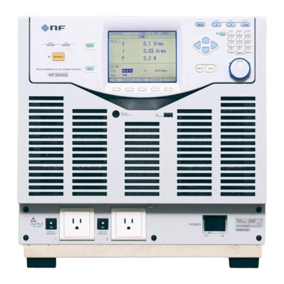
3. Basic Operation Component Name 3.1.1 Front 1. Control panel 2. Remote controller connector 3. USB memory connector 4. Front grill 5. Front grill fixation screw 6. Power switch 7. Foot Figure 3-1 Component Name (Front)(Foot Type) 8. Outlet 9. Caster 10. -
Page 45: Table 3-1 Component Name (Front)
Can be used to move this product in the horizontal location. Can be used to fix this product †‡ Adjuster Foot temporarily in the horizontal location. Note: † indicates an option Note: ‡ indicates a caster type KP3000S... -
Page 46: Rear
3. Basic Operation 3.1.2 Rear 5. GPIB connector 1. External signal input connector 2. Monitor output connector 6. RS232 connector 7. USB connector 3. SYSTEM I/O connector 4. CONTROL I/O connector 8. Air outlet 9. Power input terminal 11. Output terminal 10. -
Page 47: Table 3-2 Component Name (Rear)
Caster with the freely movable †‡ Caster front-wheels and fixed rear-wheels. Can be used to move this product in the horizontal location. Note: † indicates an option Note: ‡ indicates a caster type KP3000S... -
Page 48: Control Panel
3. Basic Operation 3.1.3 Control Panel 9. Memory key 8. LCD Screen 10. V key 11. F key 12. I key 13. SHIFT key 1. LIMIT LED 14. SHIFT LED 2. ERROR LED 15. Numeric keypad 3. OUTPUT LED 16. Arrow key 4. -
Page 49: Power On/Off
Double-check the connection to the power supply. Ensure that the cable is appropriate for the input current and firmly connected. Double-check the connection to the output. Ensure that the cable is appropriate for the output current and firmly connected. KP3000S... -
Page 50: Power On
1. The "NF" logo mark is displayed for a few seconds or more than 10 seconds. The length for which this logo is displayed depends on your system. -
Page 51: The Settings Loaded After Startup
For a polyphase system, although the order for turning off cabinets is not significant, a communication error message may appear if the interval between the operations of turning off the cabinets is too long. This does not cause any problem. KP3000S... -
Page 52: Basic Key Operations
3. Basic Operation Basic Key Operations 3.3.1 Changing the Output Function (Continuous Output/Sequence/Simulation) To change the Continuous output/Sequence/Simulation function, press the MENU key. This operation displays the root menu shown in Figure 3–8. Five icons are available in the root menu. The cursor location is informed by the highlighted icon. The description of the icon at the cursor location is displayed in the box located at the bottom of the screen. -
Page 53: Using Soft-Keys
Figure 3-10 The Example of a Data List Box 3.3.3 Using Soft-keys When the soft-key function is displayed at the bottom of the LCD screen as shown in Figure 3–11, pressing a soft-key performs the function assigned to that key. Soft-key function Figure 3-11 Soft-key Function KP3000S... -
Page 54: Closing Windows
3. Basic Operation 3.3.4 Closing Windows The window with the [Close] button Following three methods are available to close the window with the [Close] button shown in Figure 3–12. Move the cursor to the [Close] button in the window by using the arrow keys or the jog and press the ENTER key. -
Page 55: Entering Values (Numerical Entry Box)
To move the cursor position, use the right or left arrow key. When you press the ENTER key, the edited string is confirmed and the character string entry box is closed. KP3000S... -
Page 56: Figure 3-15 Character String Entry Box
3. Basic Operation Figure 3-15 Character String Entry Box Table 3-5 Character String Entry List Turning the jog in the counterclockwise direction Turning the jog in the clockwise direction Pressing the up arrow key Pressing the down arrow key ABCDEFGHIJKLMNOPQRSTUVWXYZabcdefghijklmnopqrstuvwxyz 0123456789!#$%&'()+,-.;=@[]^_`{}~... -
Page 57: Using Shortcut Operations (Shift Key)
3.4.11 between normal and simple. Ipk CLR Clears the current peak-hold value. 3.4.12 Note: If you change the item presented with † symbol using a Shortcut operations, the setting is not saved in the System Setting Memory (see 10.24 KP3000S... -
Page 58: Using The Continuous Function
3. Basic Operation Using the Continuous Function 3.4.1 Setting the AC/DC Mode and the Signal Source The description of the AC/DC mode is shown in Table 3-7. The description of the signal source is shown in Table 3-8. The selectable combinations of the AC/DC mode and the signal source are shown in Table 3-9. -
Page 59: Table 3-9 List Of The Selectable Combinations Of The Ac/Dc Mode And The Signal Source
*1: The DC voltage cannot be set in 1P3W or 3P4W of the ACDC mode. Operation procedures using soft-keys 1. Press the [Osc] soft-key and select [1:AC/DC]. 2. In the displayed selection box, select the desired AC/DC mode. KP3000S... - Page 60 3. Basic Operation 3. Press the [Osc] soft-key and select [2:Source]. 4. In the displayed selection box, select the desired signal source. Operation procedures by using shortcuts Switching the AC/DC mode Press the SHIFT key to enter the shift state (the SHIFT LED illuminates). When you press the 7 key of the numeric keypad during the shift state, the AC/DC mode is switched in the following order: AC, ACDC, DC, AC.
-
Page 61: Setting The Output Range
3P4W 0.0 to 268.4 0.0 to 536.8 Vrms External Input Gain 0.0 to 220.0 0.0 to 440.0 Times Peak current limiter (positive) Peak current limiter (negative) Refer to 10.13 RMS current limiter Voltage Setting Limit Refer to 10.14 KP3000S... -
Page 62: Setting Waveforms
3. Basic Operation Operation procedures using soft-keys 1. Press the [Osc] soft-key and select [3:Range]. 2. In the displayed selection box, select the desired output range. Operation procedures using the RANGE key The range is toggled between 100 V range and 200 V range every time you press the RANGE key. 3.4.3 Setting Waveforms You can select a waveform of the internal signal source from sine wave (SIN), clipped sine wave (CLP, three types available), and arbitrary waveform (ARB, 16 types available). - Page 63 ) is displayed next to it. When you move the cursor onto the [Select] icon, the clip ratio or crest factor is displayed for the clipped sine wave, or the arbitrary waveform data name for the arbitrary waveform. When you press the ENTER KP3000S...
-
Page 64: Setting The Output Voltage (Single-Phase Output)
3. Basic Operation key, the setting window opens for the clipped sine wave or the selection window opens for the arbitrary waveform. In this window, set or select items as needed. 3.4.4 Setting the Output Voltage (Single-phase Output) Set the AC component and DC component separately for the output voltage of the internal signal source. -
Page 65: Setting The Output Voltage (Polyphase Output)
1. Check the icon in the output display area (see 5.1) is (single-phase three-wire system)/ (three-phase system). If the different icon is shown, press the [Osc] soft-key and select [5:Target Phs] [4:All Phs]. Or perform the Shortcut operation switch to [All Phs]. KP3000S... - Page 66 3. Basic Operation 2. Select the [ACV] item and then enter a numeric value. For how to enter values, see 3.3.5. Operation procedures for setting the line voltage 1. Press the [Osc] soft-key and select [5:Target Phs] [5:All Line]. Or perform the Shortcut operation to switch to [All Line].
-
Page 67: Setting The Output Frequency
The output off phase can be disabled. If disabled, the output is turned off immediately after the operation of output off. Operation procedure 1. Press the [Osc] soft-key and select [4:On/Off Phs]. The output on/off phase setting window opens. KP3000S... -
Page 68: Turning The Output On Or Off
3. Basic Operation 2. Set the on and off phase in the [On Phase] item and [Off Phase] item respectively. If you want to disable the off phase, select [Disable]. 3. Close the window. For how to close the window, see 3.3.4. -------- Notes ------------------------------------------------------------------------------------------------------------ ... -
Page 69: Using The Measurement Function
Reactive power The reactive power provided to the load. The power of the phase is displayed when in the phase voltage display. The total power of all phases is displayed when in the line voltage display. KP3000S... -
Page 70: Switching The Display Format (Rms/Avg/Peak) Of The Measured Value
3. Basic Operation Table 3-11 Main Measurement Functions (continued) Item Description Unit Power factor The power factor of the load. The power — factor of the phase is displayed when in the phase voltage display in the polyphase system. It is not displayed when in the line voltage display. - Page 71 Press the SHIFT key to enter the shift state (the SHIFT LED illuminates). When you press the 3 key of the numeric keypad during the shift state, the measuring mode is switched in the following order: RMS, AVG, Peak, RMS. Some measuring modes may be skipped and cannot be selected depending on the AC/DC mode. KP3000S...
-
Page 72: Enlarge Display Letters For The Measured Value
3. Basic Operation 3.4.11 Enlarge Display Letters for the Measured Value You can switch the measured value display mode between normal (normal) and the mode in which the letters are enlarged (simple) shown in Figure 3–16. In the Simple View mode, three types of measured values are displayed. - Page 73 1. In the Simple View mode, press the [Measure] soft-key and select [5:Disp Item]. The setting window for display items opens. 2. In the [Item1] to [Item3] items, select measured values to be displayed. 3. Close the window. For how to close the window, see 3.3.4. KP3000S...
-
Page 74: Clearing The Output Current Peak-Hold Value
3. Basic Operation Selecting the measured value being displayed in the Simple View mode (procedure 2) In the Simple View mode, hover the cursor over the measured value item and press the ENTER key. The selection box for choosing display items opens. 3.4.12 Clearing the Output Current Peak-hold Value The output current peak-hold value is the maximum absolute value of the measured output current peak value, which is then updated appending signs and held. - Page 75 Clearing the current peak-hold value Press the SHIFT key to enter the shift state (the SHIFT LED illuminates). When you press the +/ key in the numeric keypad in the shift state, the output current peak-hold value is cleared. KP3000S...
-
Page 76: Switching The Target Phase Of Which The Measured Values Are Displayed (Polyphase Output)
3. Basic Operation 3.4.13 Switching the Target Phase of which the Measured Values are Displayed (Polyphase Output) You can switch the phase of which the measured values are displayed on the LCD screen of L1 cabinet in the polyphase system. You can select the line voltage display. -------- Notes ------------------------------------------------------------------------------------------------------------ ... - Page 77 L1 L2 L1-L2 L1 ... in the single-phase three-wire. In the three-phase, it is switched in the order of L1 L2 L3 L1-L2 L2-L3 L3-L1 L1 ... KP3000S...
-
Page 79: Advanced Operation
4.24 Power Unit Energization Setting (Using Under the Restricted Rated Power) ·································· 184 4.25 Key Lock ······················································· 186 4.26 Beep ···························································· 186 4.27 Changing the Background Color and the Contrast of the Screen ················································· 187 4.28 Restoring to the Factory Default Setting (Reset) ···· 188 KP3000S... -
Page 80: Using Limiter, Setting Limiter
4. Advanced Operation Using Limiter, Setting Limiter 4.1.1 Use Peak Current Limiter Peak value of output current is limited by the peak current limiter. While the limiter is working, icon is displayed and LIMIT LED illuminates. Setting values of peak current limiter are variable, and kept independently for each of 100 V and 200 V ranges. - Page 81 2. In the [+Iop]/[ Iop] item, set the peak current limiter value of positive/negative. 3. Set the [Output OFF] item as [Enable] or [Disable]. When setting to [Enable], also set the time from the start of limiter operation to the output off. 4. Close the window. KP3000S...
-
Page 82: Using Rms Current Limiter
4. Advanced Operation 4.1.2 Using RMS Current Limiter Effective value of output current is limited by the RMS current limiter. While the limiter is working, icon is displayed and LIMIT LED illuminates. Setting values of RMS current limiter are variable, and kept independently for each of 100 V and 200 V ranges. -
Page 83: Using Voltage Setting Range Limit
When the line voltage setting (effective value setting) is selected in balanced mode, it is converted into the effective value setting of the phase voltage according to the following formula and kept in this product. KP3000S... - Page 84 4. Advanced Operation Balanced three-phase output: Phase voltage Line voltage Balanced single-phase three-wire output: Phase voltage Line voltage The limiting value should be set using the effective value or the positive and negative peak value. The effective value can be used only when in the AC mode and the waveform is a sine wave or a clipped sine wave.
-
Page 85: Using Frequency Setting Range Limit
For the default setting range, see 10.14. -------- Notes ------------------------------------------------------------------------------------------------------------ The frequency setting range limit is useful for the prevention of an unintended frequency setting when a setting value is rapidly increased or decreased by using the shuttle. ----------------------------------------------------------------------------------------------------------------------------- KP3000S... -
Page 86: About Wattage Limiter
4. Advanced Operation Operation procedure 1. Push [Limiter] soft-key to select 3: V/F Limiter (or push ). Opens the setting window for the voltage/frequency setting range limit. 2. Set values in the [Freq Up]/[Freq Lo] item so that the upper value of the frequency setting range limit is higher than or equal to the lower limit. -
Page 87: Using Sequence Function
The sequence setting is kept per AC/DC mode. Every time AC/DC mode is changed, the sequence setting that is already kept is loaded. The sequence setting is cleared when the power is turned off. To save the setting, you need to save it in internal memory or USB memory (see 4.9). KP3000S... -
Page 88: Figure 4-1 Step-Control Parameters And Intra-Step Parameters
4. Advanced Operation Step One sequence consists of a series of two or more steps. To use Sequence function, first set each step. Step-control Parameters and intra-Step Parameters There are the following two major types of parameters in Sequence function: ... -
Page 89: Figure 4-2 Step Behavior
Sequence function. Set these parameters beforehand using continuous output function. Sequence function displays the measured value in Sequence function, which is equivalent to that of the continuous output function. However, harmonic current measurement (see 4.4) cannot be displayed. ----------------------------------------------------------------------------------------------------------------------------- KP3000S... -
Page 90: Parameters Of Sequence Function
4. Advanced Operation 4.2.2 Parameters of Sequence Function Table 4-2 shows the parameters of Sequence function. The common parameters are common to one sequence. In Sequence function, signal source is fixed to INT. In each step, set the step-control parameter and the intra-Step parameter. As for intra-Step parameter, the item and range that can be set differ depending on the output range (100 V/200 V range) and output mode (AC-INT/ACDC-INT/DC-INT) as in the case of continuous output function. - Page 91 Stop Phase. ----------------------------------------------------------------------------------------------------------------------------- Step sync code output (Code) State output to CONTROL I/O connector. Code to output while the execution of the step, which is specified by 2-bit H/L. KP3000S...
-
Page 92: Figure 4-3 Stop Phase
4. Advanced Operation Start Phase (StartPhs) Determines the phase of AC waveform of L1 phase when the step starts. The phase when a step starts in L2 and L3 phase of polyphase system is the addition of the setting value of intra-Step parameter Phase and the setting value of the step Start Phase. -
Page 93: Example Of Output Using Sequence Function
(No. 4). ----------------------------------------------------------------------------------------------------------------------------- 4.2.4 Process Flow in a Step Figure 4–5 shows the process flow in one step. The transition such as Figure 4–6 occurs by branch operation or stop operation, regardless of the flow in the step. KP3000S... -
Page 94: Figure 4-5 Process Flow In Sequence Step
4. Advanced Operation Start 開始 During the specified Step Time, output is performed according to 指定のステップ時間の間,ステップ動作種別設定に従い出力 the Step Behavior setting. When If Hold operation is executed on します。途中でホールド操作が行われたら,リジューム操作 the way, output state is kept until Resume operation is executed. が行われるまで出力状態を保持します。 When step termination setting is Hold, output state is kept until ステップ終端設定がホールドなら,リジューム操作が行われ... -
Page 95: Edit A Sequence
Transit to Sequence Edit View Press the MENU key to open the root menu, then select [Sequence] (see 3.3.1). While the Sequence Control View is displayed, if you push the [Edit] soft-key, the execution transitions to the Sequence Edit View. Sequence icon KP3000S... - Page 96 4. Advanced Operation Edit a sequence 1. Push [Osc] soft-key on Sequence Edit View, then select AC/DC mode and 100 V/200 V range. To edit the saved sequence, load the sequence (see 4.2.6). 2. Set the parameter of each step. You can move between each step by changing [Step No.]. Step number PROGRAMMABLE AC/DC POWER SOURCE...
- Page 97 3. You can select s or ms as the unit of Step Time by selecting [Misc] soft-key [1: TimeUnit]. 4. You can set polarity of trigger output and pulse width by selecting [Misc] soft-key [2: Trig Out]. KP3000S...
-
Page 98: Load A Sequence
4. Advanced Operation 4.2.6 Load a Sequence -------- Notes ------------------------------------------------------------------------------------------------------------ When the sequence is loaded, the sequence being edited at that time is discarded. In Sequence Control View, a sequence cannot be loaded. ----------------------------------------------------------------------------------------------------------------------------- Load the sequence stored in the internal memory 1. - Page 99 3. Specify the memory number of the sequence to be loaded in [Memory No.] item, and then push [Recall] soft-key. 4. The confirmation window for loading the sequence opens. Select [OK]. The sequence with the specified memory number is loaded. KP3000S...
- Page 100 4. Advanced Operation Load the sequence stored in the USB memory For how to connect USB memory to this product, and how to disconnect from this product, see 4.9. 1. In Sequence Edit View, select [File] soft-key [2: Recall]. Sequence Recall View is opened. 2.
- Page 101 -------- Notes ------------------------------------------------------------------------------------------------------------ The number of sequence data files saved in a USB memory should be 500 or less. If the number of files exceeds this limit, the product cannot recognize the sequence data files in the USB memory. ----------------------------------------------------------------------------------------------------------------------------- KP3000S...
-
Page 102: Execute A Sequence
4. Advanced Operation 4.2.7 Execute a Sequence The edited sequence can be executed after converted to executable program by compile operation. Transition to Sequence Control View When pushing [Compile] soft-key in the Sequence Edit View, the edited sequence is compiled, and then the screen transitions to Sequence Control View. - Page 103 Sequence Control View. At this point, the output is in the state set in the step No. 0. When a sequence is stopped, the icon is displayed. 2. When pushing [Start] soft-key, the sequence is started. While the sequence is executed, icon is displayed. KP3000S...
- Page 104 4. Advanced Operation 3. When [Stop] soft-key is pushed while sequence is executed, the execution transitions to the output state that is set in the step No. 0, and then sequence is terminated. The output remains -------- Notes ------------------------------------------------------------------------------------------------------------ In the output off state, the sequence cannot be started. ...
- Page 105 1. When pushing [Hold] soft-key while a sequence is executed, the sequence is suspended. The output state is kept while suspended. Icon is displayed. 2. To restart the sequence, push [Resume] soft-key. If you push [Stop] soft-key, the execution transitions to step No. 0 and the sequence is terminated. KP3000S...
-
Page 106: Save A Sequence
4. Advanced Operation Branch a sequence If you push [Bran1] or [Bran2] soft-key while a sequence is executing, the execution transitions to the branch step 1 or 2 that is set in the step being executed. 4.2.8 Save a Sequence -------- Notes ------------------------------------------------------------------------------------------------------------ ... - Page 107 3. Specify the memory number of location to save in [Memory No.] item, and then push [Store] soft-key. 4. A window to confirm the save name opens. Enter the name, and then select [OK]. For how to enter a string, see 3.3.6. KP3000S...
- Page 108 4. Advanced Operation Save a sequence to USB memory For how to connect USB memory to this product, and how to disconnect from this product, see 4.9. 1. In Sequence Edit View, select [File] soft-key [1: Store]. Sequence Store View is opened. 2.
- Page 109 -------- Notes ------------------------------------------------------------------------------------------------------------ The number of sequence data files saved in a USB memory should be 500 or less. If the number of files exceeds this limit, the product cannot recognize the sequence data files in the USB memory. ----------------------------------------------------------------------------------------------------------------------------- KP3000S...
-
Page 110: Clear/Rename Sequence
4. Advanced Operation 4.2.9 Clear/Rename Sequence Clear/Rename a sequence saved in internal memory 1. In Sequence Edit View, select [File] soft-key [1: Store]. Sequence Store View is opened. 2. In the [To] item, select [1: System]. PROGRAMMABLE AC/DC POWER SOURCE... - Page 111 3. Specify the number of memory to be operated in [Memory No.] item. 4. To clear, push [Clear] soft-key. Confirmation message is displayed. Select [OK]. In the cleared number of the memory, the sequence data at factory shipment is stored. KP3000S...
- Page 112 4. Advanced Operation 5. To rename, push [Rename] soft-key. Rename window opens. Enter a new name and then select [OK]. For how to enter a string, see 3.3.6. Delete/Rename a sequence saved in USB memory For how to connect USB memory to this product, and how to disconnect from this product, see 4.9. 1.
- Page 113 2. In the [To] item, select [2: USB]. 3. Select the data that is the target of the operation in the data list box. 4. To clear, push [Delete] soft-key. Confirmation message is displayed. Select [OK]. The corresponding file in USB memory is deleted. KP3000S...
-
Page 114: Set So As The Sequence Function Is Selected At Power-On
4. Advanced Operation 5. To rename, push [Rename] soft-key. Rename window opens. Enter a new name and then select [OK]. For how to enter a string, see 3.3.6. 4.2.10 Set so as the Sequence Function is Selected at Power-on You can set so as the Sequence function is selected at power-on. ... -
Page 115: Sequence Control By External Control
-------- Notes ------------------------------------------------------------------------------------------------------------ You cannot transition to root menu by pushing the MENU key in the Sequence Control View. To transition to the root menu, first move to the Sequence Edit View and then push the MENU key. ----------------------------------------------------------------------------------------------------------------------------- KP3000S... -
Page 116: Figure 4-7 Sequence Edit View
4. Advanced Operation Sequence Edit View Icon Step number Step-control parameter Intra-Step parameter Figure 4-7 Sequence Edit View Sequence Control View (output off state/sequence stopped) Icon Measured Value to be displayed Output setting of step No.0 Figure 4-8 Sequence Control View (Output Off State) ... -
Page 117: Using Power Fluctuation Testing (Simulation) Function
Abnormal, Trans 2, and Normal 2. Before the simulation starts, KP3000S stands by at the Initial Step. During the simulation, the step changes in the order of Initial, Normal 1, Trans 1, Abnormal, Trans 2, and Normal 2. After the simulation ends, KP3000S returns to the Initial Step and stands by. Step parameter Each parameter of Step Time, AC voltage, frequency, start phase, stop phase, trigger output, and synchronization output can be set for each step. -
Page 118: Simulation Function Parameters
4. Advanced Operation Initial Step Initial Step is assigned to the stand-by state before the simulation starts. KP3000S also moves to the Initial Step and becomes stand-by state after the simulation ends, except when the repeat count is specified to 0 (= infinite count). -
Page 119: Figure 4-11 Simulation Function Steps
Stop Phase, then performs the next step. When OFF is selected, the step transitions to the next step when the Step Time has elapsed regardless of the phase. When selecting ON, a numerical entry box in which you can specify the stop KP3000S... -
Page 120: Output Examples Using Simulation Function
The simulation in a series is repeated for the repeat count + 1. Setting the repeat count to zero (0) means an infinite count. When Repeat is set to OFF, the KP3000S executes the simulation only once and finishes it without performing the repeat operation. -
Page 121: Figure 4-13 Voltage Change Simulation Example
Step Time — 0.02 s 0.5 s AC voltage 100 V 100 V — 70 V — — Frequency 50 Hz 50 Hz — 50 Hz — — Start phase — — Stop Phase — — Repeat count 2 times KP3000S... -
Page 122: Process Flow In A Step
Transitions to the next step 次ステップへ移行 Figure 4-14 Process Flow through Simulation Steps Transitions to the Initial Step KP3000S transitions to the Initial Step when Simulation ending operation is =End of simulation performed. Figure 4-15 Stop Operation 4.3.5 Editing Simulation -------- Notes ------------------------------------------------------------------------------------------------------------ ... - Page 123 1. In the Simulation Edit View, press the [Osc] soft-key, and then select 100 V or 200 V range. To create a new simulation from an existing one, load the existing one (see 4.3.6). 2. Set the parameter of each step. You can move between each step by changing [Step] item. KP3000S...
- Page 124 4. Advanced Operation 3. You can select s or ms as the unit of Step Time by selecting [Misc] soft-key [1: TimeUnit]. 4. You can set polarity of trigger output and pulse width by selecting [Misc] soft-key [2: Trig Out].
-
Page 125: Loading A Simulation
Simulation cannot be loaded in the Simulation Control View. ----------------------------------------------------------------------------------------------------------------------------- Load the simulation stored in the internal memory 1. In Simulation Edit View, select [File] soft-key [2: Recall]. The Simulation Recall View opens. 2. In the [From] item, select [1: System]. KP3000S... - Page 126 4. Advanced Operation 3. Specify the memory number of simulation to be loaded in [Memory No.] item, and then push [Recall] soft-key. 4. The confirmation window for loading the simulation opens. Select [OK]. The simulation with the specified memory number is loaded. ...
- Page 127 4.3 Using Power Fluctuation Testing (Simulation) Function 1. In Simulation Edit View, select [File] soft-key [2: Recall]. The Simulation Recall View opens. 2. In the [From] item, select [2: USB]. 3. In the data list box, select the simulation to load. KP3000S...
-
Page 128: Executing Simulation
4. Advanced Operation 4. Push the [Recall] soft-key. 5. The confirmation window for loading the simulation opens. Select [OK]. The specified simulation data is loaded. -------- Notes ------------------------------------------------------------------------------------------------------------ The number of simulation data files saved in a USB memory should be 500 or less. If the number of files exceeds this limit, the product cannot recognize the simulation data files in the USB memory. - Page 129 Simulation Control View. At this point, the output is in the state set in the Initial Step. When a simulation is stopped, the icon is displayed. 2. Press the [Start] soft-key to start the simulation. While the simulation is executed, icon is displayed. KP3000S...
-
Page 130: Saving Simulation
4. Advanced Operation 3. When [Stop] soft-key is pushed while simulation is executed, the execution transitions to the output that is set in the Initial Step, and then simulation is terminated. -------- Notes ------------------------------------------------------------------------------------------------------------ In the output off state, the simulation cannot be started. ... - Page 131 1. In the Simulation Edit View, press the select the [File] soft-key - [1: Store]. The Simulation Store View opens. 2. In the [To] item, select [1: System]. 3. Specify the memory number of location to save in [Memory No.] item, and then push [Store] soft-key. KP3000S...
- Page 132 4. Advanced Operation 4. A window to confirm the save name opens. Enter the name, and then select [OK]. For how to enter a string, see 3.3.6. Saving the simulation in the USB memory For how to connect USB memory to this product, and how to disconnect from this product, see 4.9. 1.
- Page 133 3. Push [New] soft-key to save for the first time. To overwrite the existing data, select the data to be overwritten in data list box, and push [Store] soft-key. 4. A window to confirm the save name opens. Enter the name, and then select [OK]. For how to enter a string, see 3.3.6. KP3000S...
-
Page 134: Clear/Rename Simulation
4. Advanced Operation -------- Notes ------------------------------------------------------------------------------------------------------------ The number of simulation data files saved in a USB memory should be 500 or less. If the number of files exceeds this limit, the product cannot recognize the simulation data files in the USB memory. - Page 135 3. Set the number of memory to be operated in [Memory No.] item. 4. To clear, push [Clear] soft-key. Confirmation message is displayed. Select [OK]. In the cleared number of the memory, the simulation data at factory shipment is stored. KP3000S...
- Page 136 4. Advanced Operation 5. To rename, push [Rename] soft-key. Rename window opens. Enter a new name and then select [OK]. For how to enter a string, see 3.3.6. Erasing/renaming a simulation saved in USB memory For how to connect USB memory to this product, and how to disconnect from this product, see 4.9. 1.
- Page 137 2. In the [To] item, select [2: USB]. 3. Select the data that is the target of the operation in the data list box. 4. To clear, push [Delete] soft-key. Confirmation message is displayed. Select [OK]. The corresponding file in USB memory is deleted. KP3000S...
-
Page 138: Set So As The Simulation Function Is Selected At Power-On
4. Advanced Operation 5. To rename, push [Rename] soft-key. Rename window opens. Enter a new name and then select [OK]. For how to enter a string, see 3.3.6. 4.3.10 Set so as the Simulation Function is Selected at Power-on You can set so as the Simulation function is selected at power-on. ... -
Page 139: Simulation Control By External Control
-------- Notes ------------------------------------------------------------------------------------------------------------ You cannot transition to root menu by pushing the MENU key in the Simulation Control View. To transition to the root menu, first move to the Simulation Edit View and then push the MENU key. ----------------------------------------------------------------------------------------------------------------------------- KP3000S... -
Page 140: Figure 4-16 Simulation Edit View
4. Advanced Operation Simulation Edit View Icon Step explanation diagram Repeat Step selection Step parameter Figure 4-16 Simulation Edit View Simulation Control View (output off state, simulation stopped) Icon Measured Value to be displayed Output setting of initial step Figure 4-17 Simulation Control View (Output Off State, Simulation Stopped) ... -
Page 141: Measuring Harmonic Current
If a current with many harmonic components is supplied to the power line in high volume, the line voltage is distorted, causing problems such as malfunction of devices and overheated transformer which may result in accidents. Current 電流 電圧 Voltage Figure 4-20 Current Waveform Containing Many Harmonic Components KP3000S... -
Page 142: Basics
4. Advanced Operation 4.4.2 Basics Harmonic current measurement function is available only for the Continuous function, AC-INT, and set frequency of 50 Hz or 60 Hz. The harmonic current components up to order 40 are displayed as the RMS and a percentage to fundamental wave component. -
Page 143: Measuring Inrush Current
Figure 4–21 shows the inrush current waveform of a small electric drill. The inrush current flows at 14 A peak, which is about four times of the rated current of 3.5 A. 電圧 Voltage 100V/div 電流 Current 10A/div Figure 4-21 Inrush Current Example KP3000S... -
Page 144: Basics
4. Advanced Operation It is necessary for an electric device with a large inrush current to use a power source with a sufficient current supplying capability. With a power source that cannot supply a sufficient inrush current, some electric devices may not start as they are not supplied with necessary power. This product has the ability to supply peak current up to four times of the RMS rating. -
Page 145: Measurement Tips
Clip ratio = Clipped sine wave peak value/Original sine wave peak value As shown in Table 4-8, the output voltage setting method differs depending on the clip depth setting method. Therefore, a clip ratio less than 100% makes the output voltage smaller than the setting. KP3000S... -
Page 146: Table 4-8 Different Output Voltage Settings Depending On Clip Depth Setting Method
4. Advanced Operation Table 4-8 Different Output Voltage Settings Depending on Clip Depth Setting Method Clip Depth Setting Method Output Voltage Setting Method Crest factor Sets the RMS of the clipped waveform Clip ratio Sets the RMS of the sine wave before clipping -------- Notes ------------------------------------------------------------------------------------------------------------ ... - Page 147 3. In the [No.] item, select the clipped sine wave to load. 4. In the [Type] item, select [1: Clip] (clip ratio) or [2: CF] (crest factor). 5. In the [CF] (or [Clip]) item, enter the crest factor (or clip ratio). KP3000S...
-
Page 148: Outputting Arbitrary Waveform
4. Advanced Operation 6. To save the set content into memory, move the cursor to [Save], then press the ENTER key. 7. Move the cursor to [Close], then press the ENTER key. The clipped sine wave setting window closes. -------- Notes ------------------------------------------------------------------------------------------------------------ ... -
Page 149: Arbitrary Waveform Creation Procedure
2. Connect the USB memory that has the waveform data to this product. 3. Press the MEMORY key, or press the MENU key to move to the root menu and then select [Memory], to move to the Memory View. Select ARB Copy. KP3000S... - Page 150 4. Advanced Operation 4. In the [Direction] item, select [2: USB SYS]. 5. In the [Memory No.] item, specify the transfer destination internal memory number. 6. From the data list box, select the arbitrary waveform to transfer. PROGRAMMABLE AC/DC POWER SOURCE...
- Page 151 8. In the [Name] item, enter the arbitrary waveform data name. Or, leave it as populated which is same as the file name in the USB memory. 9. Move the cursor to [OK], then press the ENTER key. The window is closed. KP3000S...
-
Page 152: Outputting Arbitrary Waveform
4. Advanced Operation 4.7.5 Outputting Arbitrary Waveform Operation Method 1. In the [Wave] item, select [ARB]. 2. Move the cursor to [Select], then select it. The setting window for the arbitrary waveform opens. 3. From the data list box, select the arbitrary waveform to output. PROGRAMMABLE AC/DC POWER SOURCE... -
Page 153: Using Memory Function
Opening the Memory View 1. Press the MENU key to move to the root menu, then select [Memory] (or press the MEMORY key on the Continuous function screen). KP3000S... -
Page 154: Basic Setting Memory
4. Advanced Operation 2. The Memory View opens. 4.8.1 Basic Setting Memory The Basic Setting Memory collectively stores the output-related settings in the Continuous function (e.g. AC/DC mode, signal source, output range, AC setting, DC setting, current limiter, setting range limit). - Page 155 3. For the [To] item, select the destination [1: System] (internal memory) or [2: USB] (USB memory). 4. Specify the destination. (a) For the internal memory, specify the destination memory number in the [Memory No.] item, then press the [Store] soft-key. KP3000S...
- Page 156 4. Advanced Operation (b) In the case of USB memory, push [New] soft-key to save for the first time. To overwrite the existing data, select the data to be overwritten in data list box, and push [Store] soft-key. Internal memory USB memory 5.
- Page 157 (a) For the internal memory, specify the memory number in the [Memory No.] item, then press the [Recall] soft-key. (b) For the USB memory, in the data list box, select the data to load, then press the [Recall] soft-key. Internal memory USB memory 4. In the confirmation window that opens, select [OK]. KP3000S...
- Page 158 4. Advanced Operation Clearing, erasing, or renaming a Basic Setting Memory 1. In the Memory View, select [Setting Store]. 2. In the [To] item, select the object to operate [1: System] (internal memory) or [2: USB] (USB memory). 3. Specify the data to operate. (a) For the internal memory, specify the memory number in the [Memory No.] item.
- Page 159 No. 0). Erasing the basic setting data in the USB memory deletes the applicable file. 5. To rename, push [Rename] soft-key. Rename window opens. Enter a new name and then select [OK]. For how to enter a string, see 3.3.6. KP3000S...
- Page 160 4. Advanced Operation Loading the factory defaults 1. In the Memory View, select [Setting Recall]. 2. In the [From] item, select [System]. 3. Push the [Factory] soft-key. In the confirmation window that opens, select [OK]. The factory default basic setting data are loaded. PROGRAMMABLE AC/DC POWER SOURCE...
-
Page 161: Arbitrary Waveform Memory
The paragraphs below describe how to copy the arbitrary waveform data from the internal memory to the USB memory. For how to copy from the USB memory to the internal memory, see 4.7.4. 1. In the Memory View, select [ARB Copy]. KP3000S... - Page 162 4. Advanced Operation 2. In the [Direction] item, select [SYS USB]. 3. From the data list box, select the arbitrary waveform to copy. 4. Push the [Copy] soft-key. A window to confirm the save name opens. Enter the name. Select [OK] to copy.
- Page 163 1. In the Memory View, select [ARB Copy]. 2. In the [Direction] item, select the object to operate. SYS USB: Selects the internal memory as the target of the operation. USB SYS: Selects the USB memory as the target of the operation. KP3000S...
- Page 164 4. Advanced Operation 3. Select the data that is the target of the operation in the data list box. Internal memory USB memory 4. To clear/delete, push [Clear]/[Delete] soft-key. Confirmation message is displayed. Select [OK]. Clearing the internal Arbitrary Waveform Memory resets the data to triangle wave for memories from No.
-
Page 165: Sequence Memory
Refer to 4.28 SEQ Store In the Memory View, select [SEQ Store] to change to the Sequence Save View as below, allowing you to save, clear, and rename the sequence. For the operation method, see 4.2.8 and 4.2.9. KP3000S... -
Page 166: Simulation Memory
4. Advanced Operation SEQ Recall In the Memory View, select [SEQ Recall] to change to the Sequence Recall View as below, allowing you to load the sequence. For the operation method, see 4.2.6. 4.8.4 Simulation Memory The user-created simulation can be saved in the Simulation Memory. Both the internal and USB memories can be selected as the Simulation Memory. -
Page 167: Using Usb Memory Function
Before removing the USB memory from this product, always perform the eject operation (see the next section). Removing the USB memory while it is being accessed may damage the data. Do not turn off this product while it is accessing the data in the USB memory. KP3000S... -
Page 168: Using Monitor Function
4. Advanced Operation -------- Notes ------------------------------------------------------------------------------------------------------------ We do not guarantee that all USB memories can be operational with this product. Use a FAT32-formatted USB memory. This product does not support the exFAT format which began to be supported from Windows Vista SP1. ... - Page 169 1. Press the MENU key to move to the root menu, then select [System]. 2. Put the cursor on [Setup] of the [Monitor] item, then press the ENTER key. 3. «Only for polyphase system» For the [Phs] item, select the desired phase. KP3000S...
- Page 170 4. Advanced Operation 4. For the [Type] item, select the output voltage or current. 5. Put the cursor on [Close], then press the ENTER key. -------- Notes ------------------------------------------------------------------------------------------------------------ In a polyphase system, configure monitor setting for each of the phases using the L1 phase cabinet.
-
Page 171: Using Remote Sensing Function
Do not input a signal having a different electric potential from the output terminal (for example, the signal at the secondary side of transformer) into the sensing input terminal. Connect the sensing input terminal to the output voltage detecting end (for example, load end) using a cable. KP3000S... - Page 172 4. Advanced Operation Turning on/off Remote sensing function 1. Press the [Measure] soft-key, then select [2: Measure]. 2. Use the [Rmt Sense] item to turn on or off, if necessary. 3. When the Remote sensing function is turned on, the item symbol of the output voltage measured value is changed to "SV".
-
Page 173: Using Agc Function
Meanwhile, in the Autocal function, the output voltage may not be calibrated properly when the load is fluctuated, but once Autocal is turned on, there is no response time needed for calibration. ----------------------------------------------------------------------------------------------------------------------------- KP3000S... - Page 174 4. Advanced Operation Turning on the AGC function 1. Turn on the output. 2. Open the AGC/Autocal set window. Following two methods are available. (a) Shortcut operation: (b) Push the [Misc] soft-key and select [1: AGC/Auto Cal]. 3. Use the [Rmt Sense] item to set the Remote sensing function to on or off, if necessary. 4.
- Page 175 1. Open the AGC/Autocal set window. Following two methods are available. (a) Shortcut operation: (b) Push the [Misc] soft-key and select [1: AGC/Auto Cal]. 2. In the [AGC] item, select [1: OFF]. When [OFF] is selected here, the AGC calibration finishes. KP3000S...
-
Page 176: Using Autocal Function
4. Advanced Operation 3. Use the [Rmt Sense] item to set the Remote sensing function to on or off, if necessary. 4. Close the window. 4.13 Using Autocal Function The Autocal (Automatic Calibration) function calculates the ratio (calibration factor) of the output voltage measured value (effective value) versus the output voltage setting value when this function is turned on, and multiplies the gain of the output amplifier by the calculated value, intending to match the output voltage with the setting value. - Page 177 ----------------------------------------------------------------------------------------------------------------------------- Turning on the Autocal function 1. Turn on the output. 2. Open the AGC/Autocal set window. Following two methods are available. (a) Shortcut operation: (b) Push the [Misc] soft-key and select [1: AGC/Auto Cal]. KP3000S...
- Page 178 4. Advanced Operation 3. Use the [Rmt Sense] item to set the Remote sensing function to on or off, if necessary. 4. Use the [Auto Cal] item to turn on or off the Autocal function. When [ON] is selected here, the calibration factor of the Autocal function is calculated, and the calibration is started.
- Page 179 (b) Push the [Misc] soft-key and select [1: AGC/Auto Cal]. 2. In the [Auto Cal] item, select [1: OFF]. When [OFF] is selected here, the Autocal calibration finishes, and the calibration factor is cleared. KP3000S...
-
Page 180: Adjusting Dc Offset
4. Advanced Operation 3. Use the [Rmt Sense] item to set the Remote sensing function to on or off, if necessary. 4. Close the window. 4.14 Adjusting DC Offset Even when the output voltage is set to 0 V, the DC offset voltage from several mV to several tens mV may exist in the output. - Page 181 1. Press the [Misc] soft-key and select [2:DC Adjust]. The DC offset adjustment window opens. 2. «Only for the polyphase system» In the [Target Phs] item, specify the phase to perform the DC offset adjustment. In this example, the single-phase model is used, so this item is not specified (leave it as "L1"). KP3000S...
-
Page 182: Using For Unbalanced Polyphase Output
4. Advanced Operation 3. While checking the DC offset of the output voltage, adjust the value in the [DC Adj] item so that the DC offset gets close to zero. 4. Close the window. 4.15 Using for Unbalanced Polyphase Output For the polyphase system, you can set the phase voltage and the phase to be unbalanced. - Page 183 4. To unbalance the phase voltage, press the [Osc] soft-key and select [5: Target Phs], and then select the phase to set the phase voltage. Or perform the Shortcut operation switch the phase to set. Set the phase voltage in [ACV]. KP3000S...
-
Page 184: Using As Dc Power Supply
4. Advanced Operation -------- Notes ------------------------------------------------------------------------------------------------------------ When the unbalanced mode is switched to the balanced mode, the AC voltage of each phase becomes equal to the setting value of the L1 phase. The phase setting value is the value of the balanced mode (180 degrees for single-phase three-wire output, and 120 degrees and 240 degrees for three-phase output). -
Page 185: Setting Voltage Using External Dc Input Signal
(VCA, EXT, ADD). For the polyphase system, the ACV setting using VCA is common to all phases. When the switching from AC-VCA mode to ACDC mode, the signal source is forcibly set to INT. ----------------------------------------------------------------------------------------------------------------------------- KP3000S... - Page 186 4. Advanced Operation Examples 1. When the waveform is SIN, the gain is 100, and the external DC signal voltage is 1 V, the output will be a sine wave of which amplitude is 100 Vop (= 70.7 Vrms). 2.
-
Page 187: Using External Signal In Dc-Vca Mode
When the switching from DC-VCA mode to ACDC mode, the signal source is forcibly set to INT. ----------------------------------------------------------------------------------------------------------------------------- Examples When the gain is 100, and the external DC signal voltage is 1 V, the output will be a DC voltage of 100 V. KP3000S... - Page 188 4. Advanced Operation Operation procedure 1. Turn off the output, and enter the DC mode. Following two methods are available. (a) Shortcut operation: Every time you press the keys, the mode is switched to AC, ACDC, and DC in this order. (b) Press the [Osc] soft-key and select [1:AC/DC].
-
Page 189: Control Using External Control Function
The connector to be used is DBLC-J25SAF-10L9E (D-sub, 25-pin, M2.6 mm screw) manufactured by JAE. For the specification of I/O signals, see 10.26, and for the pin assignment of the CONTROL I/O connector, see Table 4-12. KP3000S... -
Page 190: Table 4-12 Control I/O Pin Assignment
4. Advanced Operation -------- Notes ------------------------------------------------------------------------------------------------------------ You can enable/disable the external control function. When the external control function is disabled, the input from the external control is not accepted, but the state output signal is output. We recommend that when the external control function is not used, the function is set to disabled to avoid malfunctioning due to any exogenous noise. - Page 191 4.18 Control Using External Control Function Enabling/disabling external control function 1. Press the MENU key to move to the root menu, then select [System]. The system setting window opens. 2. In the [Ext Control] item, select [1: Disable] or [2: Enable]. KP3000S...
- Page 192 4. Advanced Operation Setting the polarity of the state output 1. Press the MENU key to move to the root menu, then select [System]. The system setting window opens. 2. In the [ExtOut Pol] item, select [1: Negative] or [2: Positive]. PROGRAMMABLE AC/DC POWER SOURCE...
- Page 193 1. Press the MENU key to move to the root menu, then select [System]. The system setting window opens. 2. Move the cursor to [Setup] next to the [Trig Out] item, and select it. The trigger output setting window opens. KP3000S...
-
Page 194: Synchronizing The Output Frequency With The Power Line Or The External Signal
4. Advanced Operation 3. Set the polarity (Positive/Negative) in the [Polarity] item, and set the pulse width in the [Width] item. 4. Move the cursor to [OK], then press the ENTER key. The trigger output setting window is closed. 4.19 Synchronizing the Output Frequency with the Power Line or the External Signal When you select SYNC for the signal source, you can synchronize the frequency of the internal... - Page 195 3. In the [Source] item, select [Line] (power input) or [Ext] (external input signal) as the synchronization signal source. 4. When the internal signal source is synchronized with the external signal or the power line, the icon is displayed. KP3000S...
-
Page 196: Amplifying The External Signal Input
4. Advanced Operation 4.20 Amplifying the External Signal Input When you select EXT for the signal source, you can output the amplified external signal. Also, when you select ADD for the signal source, you can output the amplified external signal after the internal signal is added. -
Page 197: Turning The Output On Or Off Rapidly
4N + 3 2N + 3 2N + 3 200 kΩ 200 kΩ 200 kΩ 200 kΩ DC mode 4N + 1 4N + 1 2N + 1 2N + 1 * N indicates the number of the power units energized. KP3000S... - Page 198 4. Advanced Operation -------- Notes ------------------------------------------------------------------------------------------------------------ Even when the activation of the output relay is disabled, the relay is turned off if the protection function is activated. While the error message appearing when the protection function is activated displays "Press Enter Key," pressing the ENTER key clears the message and turns on the output relay again although the output remains off.
-
Page 199: Enabling Automatic Output-On At Power-On
----------------------------------------------------------------------------------------------------------------------------- Figure 4-24 The Message Window to be Shown Before the Automatic Output-On After the Power-On Operation procedure 1. Press the MENU key to move to the root menu, then select [System]. The system setting window opens. KP3000S... -
Page 200: Using The Emission Co
4. Advanced Operation 2. In the [PwON Output] item, select [2:ON] or [1:OFF]. When you select [ON], the automatic output-on at power-on is enabled. 4.23 Using the Emission CO Calculator This is the function for calculating and displaying the weight of the carbon dioxide (CO ) emission based on the measured value of the internal loss or the output power of this product. - Page 201 "Output" represents the output power. "Rate" represents the instantaneous and "Total" represents the integration. 3. You can change the emission coefficient in the [Coef] item. 4. If you select [Clear], the measured value in the [Total] item is cleared. KP3000S...
-
Page 202: Power Unit Energization Setting (Using Under The Restricted Rated Power)
4. Advanced Operation 4.24 Power Unit Energization Setting (Using Under the Restricted Rated Power) You can enable or disable the energization for each power unit (1.5 kVA per unit) within this product. If the smaller power is needed for handling the load, you can disable the energization for some power units to reduce the power consumption of this product. - Page 203 If a failure occurs in a power unit for some reason, you can disable the energization for that unit to restart using this product with the remaining power units. For details, see 8.1.3. ----------------------------------------------------------------------------------------------------------------------------- KP3000S...
-
Page 204: Key Lock
4. Advanced Operation 4.25 Key Lock If the key lock is enabled, the operations using keys, jog, or the shuttle are not accepted. The acceptable operations are for enabling the output off and the key lock only. This function helps to avoid the incorrect user operations during running. -
Page 205: Changing The Background Color And The Contrast Of The Screen
(b) Press the MENU key to move to the root menu, then select [System]. The system setting window opens. Put the cursor on [Setup] next to the [LCD] item, then press the ENTER key. 2. In the [Color] item, select [1: Blue] (blue tone) or [2: White] (white tone). KP3000S... -
Page 206: Restoring To The Factory Default Setting (Reset)
4. Advanced Operation 3. In the [Contrast] item, set the contrast value. 4. Close the window. -------- Notes ------------------------------------------------------------------------------------------------------------ The L2 and L3 cabinets in a polyphase system accept the Shortcut operation for this function. In this case, if other window such as the Emission CO Calculator window is being displayed, that window closes and the window for adjusting LCD opens only on the cabinet on which you performed the operation. - Page 207 Current (L1 phase) External interface × External control input Disabled Clipped sine wave Clip ratio specified Clip ratio: 100% Crest factor: 1.41 Arbitrary Waveform Memory × ARB1 to 8: Triangle wave ARB9 to 16: Square wave KP3000S...
- Page 208 4. Advanced Operation Table 4-14 Setting Items to be Reset (Continued) Setting Item Reset Factory default setting Sequence parameters × Output range: 100 V AC/DC mode: AC-INT Step Time: 0.1000 second Intra-Step behavior: Constant Waveform: SIN Frequency: 50 Hz DC voltage: 0 V AC phase voltage: 0 V Start phase: Disabled, 0 deg Stop phase: Disabled, 0 deg...
- Page 209 If you reset the product, the content in the Basic Setting Memory will not be cleared. Once restarted, the setting of the Basic Setting Memory No.1 is recalled. To reset the setting after restart to the factory default setting, see 4.8.1 to clear the content of the Basic Setting Memory No.1. ----------------------------------------------------------------------------------------------------------------------------- KP3000S...
-
Page 211: Description Of Screen And Menu
5. Description of Screen and Menu Screen Configuration ······································· 194 Menu Composition ·········································· 198 KP3000S... -
Page 212: Screen Configuration
5. Description of Screen and Menu Screen Configuration Figure 5–1 shows the basic screen configuration. It consists of display areas marked as "a" to "h". The description of each area is shown in Table 5-1. Figure 5-1 Component Name (Display Areas on the Screen) Table 5-1 Component Name (Display Areas on the Screen) Symbol Area name... -
Page 213: Status Icon
The sequence or simulation is running. 4.2.12, 4.3.12 Stand by The sequence or simulation stands by. 4.2.12, 4.3.12 Sequence suspended The sequence is suspended. 4.2.12, 4.3.12 Unadjusted Unadjusted. This icon means the abnormal — state of the product. Contact us or our agent. KP3000S... -
Page 214: Measured Value Display Items
5. Description of Screen and Menu 5.1.2 Measured Value Display Items The items displayed in the measured value area are shown in Table 5-3. Table 5-3 Measured Value Display Items Item Description Icon Represents the phase and type of the measured voltage display. Output voltage of the single-phase two-wire Phase voltage of the single-phase three-wire L1 phase Phase voltage of the single-phase three-wire L2 phase... -
Page 215: Output Setting Display Items
Gain of the external signal Source Synchronization signal source 5.1.4 Warning and Error Display If a warning or error occurs, an error message is displayed in the measured value area and the output display area. For details on error messages, see 8.1. KP3000S... -
Page 216: Menu Composition
5. Description of Screen and Menu Menu Composition The menu composition of this product is shown in Figure 5–2. Press the MENU key to move to the root menu. Root Continuous Sequence Simulation Memory System -Osc -Sequence Edit -Simulation Edit -Setting Store -Reset -Measure... -
Page 217: Menus Of The Sequence Function
Branches to a step of the branch 2. It is displayed in the sequence running state. Measure Makes the measured value display settings. It is displayed in the sequence stopped state. Edit Displays the Sequence Edit View. It is displayed in the output off state. KP3000S... -
Page 218: Menus Of The Simulation Function
5. Description of Screen and Menu 5.2.3 Menus of the Simulation Function The menus of the Simulation function are shown in Table 5-7. You can open each menu by using a soft-key. For how to use the Simulation function, see 4.3. Table 5-7 Menus of the Simulation Function Menu Description... -
Page 219: System Menus
Disconnects the USB memory before removing it. Trig Out Makes the trigger output settings in the Sequence and the 4.2,4.3 Simulation. PU-ON Makes the power unit energization settings. 4.24 Information Displays the system information. ExtOut Pol Specifies the external control state output polarity. 4.18 KP3000S... -
Page 221: Remote Control
6. Remote Control Communication Interface ·································· 204 Remote/Local State Switching ··························· 210 KP3000S... -
Page 222: Communication Interface
6. Remote Control Communication Interface This product is provided with the USB, RS232, and GPIB communication interfaces and is remote-controllable by a computer. The remote control allows almost all the operations available on the control panel to be performed. In addition, it can read the internal state such as setting values and errors. - Page 223 2. Put the cursor on [Setup] next to the [Remote] item, then press the ENTER key. The remote setting window opens. 3. In the [Interface] item, select [USB]. 4. The window shows [Terminator] and [USB ID]. For the USB ID, see the explanation in the next section. Select [OK] to close the window. KP3000S...
-
Page 224: Rs232
The use of USB hub may cause the product not to communicate properly. ----------------------------------------------------------------------------------------------------------------------------- About USB ID Used for a system connected with multiple KP3000S programmable AC/DC power sources through USB, to enable the application identify each source. The USB ID is represented in the following format. - Page 225 6.1 Communication Interface 2. Put the cursor on [Setup] next to the [Remote] item, then press the ENTER key. The remote setting window opens. 3. In the [Interface] item, select [RS232]. 4. Set each item. KP3000S...
-
Page 226: Gpib
6. Remote Control 5. Use a D-sub 9-pin cross cable to connect this product to the computer. The connector is on the rear of this product. -------- Notes ------------------------------------------------------------------------------------------------------------ Avoid use in a place that has power fluctuation or under electrically noisy environment. ... - Page 227 2. Put the cursor on [Setup] next to the [Remote] item, then press the ENTER key. The remote setting window opens. 3. In the [Interface] item, select [GPIB]. 4. In the [Address] item, set the address. [Terminator] is fixed to "LF". KP3000S...
-
Page 228: Remote/Local State Switching
6. Remote Control 5. Use a GPIB cable to connect this product to the computer. The connector is on the rear of this product. Turn off this product and the computer before connecting or disconnecting the cable. -------- Notes ------------------------------------------------------------------------------------------------------------ ... -
Page 229: Options
7. Options Outlet ··························································· 212 Casters ························································· 212 Application Software ········································ 212 System Cable (for Polyphase System) ················ 213 Remote Controller ··········································· 213 Replacement Air Filter ····································· 214 Rack-Mount Adapter ········································ 214 Additional Cable ············································· 214 KP3000S... -
Page 230: Outlet
7. Options Outlet Two outlets for Japan/North America (NEMA 5-15, available in 100 V range) are added at the lower front. The output terminals, the maximum voltage, the maximum current, and available output range are listed in Table 7-1. The outlet is dedicated to AC output. It can be used in the AC or ACDC mode. For information on outlet, see 2.5. -
Page 231: System Cable (For Polyphase System)
This option can be requested at the time of order or added after the purchase. For the remote controller operations, see the instruction manual that comes with the remote controller. Model name: DP008 Product name: Remote Controller Figure 7-1 Remote Controller External View KP3000S... -
Page 232: Replacement Air Filter
7. Options Replacement Air Filter A replacement air filter on the front grill. This option can be requested at the time of order or added after the purchase. Model name: PA-001-1966 Product name: Replacement air filter Front grill Figure 7-2 Front Grills Rack-Mount Adapter The rack-mount adapter is a set of brackets used to mount the product on the EIA or JIS standard compliant rack. -
Page 233: Troubleshooting
8. Troubleshooting Error Messages and Error Handling ···················· 216 When a Failure is Suspected ····························· 223 KP3000S... -
Page 234: Error Messages And Error Handling
8. Troubleshooting Error Messages and Error Handling 8.1.1 Error Message Screen An error message screen opens as shown in Figure 8–1, for example, in case that the protection function is activated. The description of each item is shown in Table 8-1. Figure 8-1 Error Message Screen Example Table 8-1 Description of the Error Message Screen Symbol... -
Page 235: If An Error Occurs Repeatedly
If the error still exists, the product or the power unit in the product may be faulty. Repair is needed in this case. Contact the seller (NF Corporation or our agent) from whom you purchased the product. Even though one of the power units is faulty, the product can be used by disconnecting the faulty power unit and using the rest of them. -
Page 236: Protection Operation Types
8. Troubleshooting -------- Notes ------------------------------------------------------------------------------------------------------------ The E mark does not mean it is faulty but indicates the protection operation was activated. In some cases such as the protection operation was activated in a chain-reaction manner, the E mark may appear on a normal power unit. A power unit is judged as faulty by checking whether the error repeats or not after the power unit is restarted as described in the step 2. -
Page 237: Error Message List
Remote Controller Error Message Communication with the remote controller display only cannot be made. Make sure the remote controller cable is connected properly. Internal Memory Error Message The internal memory has an error. display only KP3000S... - Page 238 Calibration Data Error ME Message The adjustment data is abnormal. Cycle the display only power. If it still occurs, contact the seller (NF Corporation or our agent) from whom you purchased the product. Line Overvoltage System The power input voltage is excessive. Check Lock if the power input is appropriate.
- Page 239 Power Unit Internal Error Output Off This is a power unit internal error. If it occurs repeatedly, contact the seller (NF Corporation or our agent) from whom you purchased the product. Limiting The active wattage limiter is activated.
- Page 240 8. Troubleshooting Table 8-2 Error Message List (Continued) Message Protection type Cause or Necessary action Polyphase Connection Message A phase configuration is detected that is Updated display only different from the previous one. Icon The power unit or the system has not display been adjusted.
-
Page 241: When A Failure Is Suspected
When a Failure is Suspected When a symptom occurs that suspects a failure, take an action according to Table 8-3. If it does not solve the problem, contact the seller (NF Corporation or our agent) from whom you purchased the product. - Page 242 8. Troubleshooting Table 8-3 Actions When a Failure is Suspected (Continued) Category Symptom Possible Cause Necessary Actions Problem at The line The signal source is not Set the signal source to SYNC and output setting synchronization set to SYNC. the external synchronization signal source to LINE.
- Page 243 4.20 A low frequency For a frequency lower than 10 Hz, the (less than 10 Hz) measurement cycle is a fixed value and is set. thus the measured value may not be stable. KP3000S...
- Page 244 8. Troubleshooting Table 8-3 Actions When a Failure is Suspected (Continued) Category Symptom Possible Cause Necessary Actions Limiter/setti The output The output current While the peak current limiter is ng range current overshoot occurred for activated, the overshoot may limitation- peak-hold value the limit value.
- Page 245 4.1.1 Memory The memory The output is on. The output on state does not allow function- cannot be the recall. Turn the output off. related recalled. problem KP3000S...
- Page 246 8. Troubleshooting Table 8-3 Actions When a Failure is Suspected (Continued) Category Symptom Possible Cause Necessary Actions Sequence/ The Sequence The output is off. Turn on the output, then start the Simulation- cannot be sequence. related started. problem The specified The Stop Phase is When the stop phase setting is Step Time is...
-
Page 247: Maintenance
9. Maintenance Preface ························································· 230 Daily Maintenance ·········································· 230 Storage, Repackaging, Transportation ················· 232 Checking Firmware Version ······························ 232 KP3000S... -
Page 248: Preface
9. Maintenance Preface This chapter describes: cautions and storing for nonuse over a long period, and cautions and repackaging for transportation. For the simple operation check, see 2.7. Daily Maintenance The product shall be installed in a location that satisfies the installation conditions (see 2.2). ... - Page 249 Hold the front grill at the bottom left and right sides, and pull it out toward you to release it. Move the front grill upward and toward you. Unhook and remove it as letting the control panel through it. KP3000S...
-
Page 250: Storage, Repackaging, Transportation
9. Maintenance 4. Remove the air filters from the back of each front grill. Be careful with the small claws on the front grill that hold the air filters. 5. Rinse the removed air filters with water to remove dirt and clog. Dry them completely. 6. - Page 251 9.4 Checking Firmware Version 2. Put the cursor on [View] next to the [Information] item, then press the ENTER key. 3. The Information window opens. The firmware version is shown at the [Firmware Version] item. KP3000S...
-
Page 253: Specifications
10.28 USB Memory Interface ····································· 258 10.29 Waveform Monitor Output ································· 259 10.30 Safety and EMC ············································· 259 10.31 Operation Environment ···································· 259 10.32 Externals, Weight, and Terminal Block ················ 260 10.33 Option ·························································· 261 10.34 Outline Dimensional Drawing ···························· 262 KP3000S... -
Page 254: Output Function
A value without the accuracy is the nominal value or representative value (shown as typ.). KP3000S corresponds to Clause 2 (8) Frequency converter, Appendix 1 of Export Trade Control Ordinance. The permission for exportation of the Japanese Administration is necessary for export outside Japan. -
Page 255: Ac/Dc Mode
10.3 AC/DC Mode 10.3 AC/DC Mode KP3000S AC/DC mode AC, AC+DC, DC Description The signal source and amplification section of this product are AC-coupled, and the DC component is canceled. Only the AC output setting of 40 Hz or higher is available. -
Page 256: Signal Source
10. Specifications 10.4 Signal Source KP3000S Signal source INT, VCA, SYNC,EXT, ADD Description Uses the internal signal source. Sets the output voltage, output waveform, frequency, output on phase, and output off phase by using the panel or the external interface such as USB. -
Page 257: Ac Output
10.5 AC Output 10.5 AC Output [V]=Vrms, [A]=Arms, and the power supply input voltage is 200 V, unless otherwise noted. KP3000S Mode Single-phase two-wire Floating output, the Lo terminal can be grounded. Rated output voltage 100 V / 200 V Voltage setting range 0.0 V to 155.0 V / 0.0 V to 310.0 V... - Page 258 10. Specifications [V]=Vrms, [A]=Arms, and the power input voltage is 200 V, unless otherwise noted. Polyphase system using KP3000Ss Mode Three-phase four-wire Single-phase three-wire (Y-connection) Floating output (Connect Lo terminals to each other), the Lo terminal can be grounded. Setting mode Balanced mode, Unbalanced mode Rated output voltage 100 V / 200 V...
-
Page 259: Dc Output
10.6 DC Output [V]=Vdc, [A]=Adc, the power input voltage is 200 V, and the polarity is relative to the Lo terminal, unless otherwise noted. KP3000S Mode Floating output, the Lo terminal can be grounded. Rated output voltage 100 V / 200 V 220.0 V to +220.0 V / 440.0 V to +440.0 V... -
Page 260: Distortion Of Output Voltage Waveform
*20: For power input 200 V, no load, the rated output voltage, DC or 45 Hz to 65 Hz. 10.8 Distortion of Output Voltage Waveform KP3000S Distortion 0.5% or lower (Phase voltage) (40 Hz to 550 Hz, 50% or higher of the rated output voltage, the maximum current or lower, AC and AC+DC modes, THD+N) 10.9... -
Page 261: Measurement Function
10.11 Measurement Function 10.11 Measurement Function All accuracy of the measurement function is indicated for 23°C5°C. View KP3000S Normal Displays almost all the measured and setting values excluding the harmonic current measurement on one screen. Simple Enlarges and displays three items among all the measured values except the harmonic current measurement. - Page 262 10. Specifications Current (phase current) KP3000S Effective Full scale 40 A / 20 A value (rms) Resolution 0.01 A Accuracy DC, 45 Hz to 65 Hz (0.5% of rdg + 0.08 A / 0.04 A) 40 Hz to 550 Hz ...
-
Page 263: Power Unit Energization Setting
10.12 Power Unit Energization Setting Load power factor, Load crest factor KP3000S Power Measurement 0.00 to 1.00 factor range Resolution 0.01 Crest Measurement 0.00 to 50.00 factor range Resolution 0.01 Note: The power factor is not displayed in the DC mode. -
Page 264: Current Limiter
In the polyphase system, the settings are made for the phase current and common to all the phases. Peak current limiter KP3000S Positive Setting Range +15.0 A to +126.0 A / +7.5 A to +63.0 A... -
Page 265: Setting Range Limit Function
EXT and ADD. In the polyphase system, the setting is common to all the phases. Voltage setting limit 1 (in the AC mode, and sine wave or clipped sine wave is selected) KP3000S Setting range Phase voltage setting (effective value) 0.1 V to 155.0 V / 0.1 V to 310.0 V... -
Page 266: Remote Sensing
Effective only for AC-INT, AC-VCA, AC-SYNC, DC-INT, and DC-VCA and when the waveform is sine wave or DC. It is turned off when the Sequence or Simulation is selected. It cannot be selected when the Autocal is set to on. KP3000S Response Within 100 ms (typ.) -
Page 267: Autocal (Output Voltage Compensation)
Effective only for AC-INT, AC-VCA, AC-SYNC, DC-INT, and DC-VCA and when the waveform is sine wave or DC. It is turned off when the Sequence or Simulation is selected. It cannot be selected when the AGC is set to on. KP3000S Restriction The output voltage setting is 8 V or higher when on Within 10% (difference between the output voltage and measured value) -
Page 268: Sequence
10. Specifications 10.18 Sequence Effective only for AC-INT, AC+DC-INT, and DC-INT. KP3000S Number of memories 5 (non-volatile) Number of steps Maximum 255 (for each sequence) Setting range of Step 0.0010 s to 999.9999 s Time Intra-Step behavior Constant, Keep, Linear Sweep... -
Page 269: Simulation
It can be used only for AC, sine wave, and AC+DC-INT. Note that it does not support IEC or other standard test. In the polyphase system, only the balanced mode is available. KP3000S Number of memories 5 (non-volatile) -
Page 270: Clipped Sine Wave
10. Specifications 10.20 Clipped Sine Wave The peak clipped sine wave can be output, based on the crest factor (CF) setting or the percent setting to the peak value. KP3000S Number of memories 3 (non-volatile) Variable range 1.10 to 1.41 Factory default 1.41... -
Page 271: External Signal Input
When the signal source is SYNC, you can select whether to synchronize with this external signal input or the power input frequency of the product. When synchronizing with the power input frequency, no signal input is needed. KP3000S Factory default Synchronization signal... -
Page 272: External Signal Input (Only Ext And Add)
EXT: Output voltage (V) = External signal input (V) x Gain (V/V) ADD: Output voltage (V) = External signal input (V) x Gain (V/V) + Internal signal source setting Factory KP3000S default Setting Range for gain 100 V range: 0.0 to 220.0 times 200 V range: 0.0 to 440.0 times... -
Page 273: Memory Function
Power unit energization setting All enabled (energization) Remote sensing General function See 10.23 (excluding the time unit setting of the Step Time for the Sequence and Simulation) Monitor output target Current (L1 phase) External interface External control input Disabled KP3000S... -
Page 274: Self-Diagnosis/Protection Function
10. Specifications 10.25 Self-diagnosis/Protection Function At power-on Description ROM check Checks the internal ROM. RAM check Checks the internal RAM. Basic setting Checks the Basic Setting Memory. Memory check System Setting Memory Checks the System Setting Memory. check Waveform Memory Checks the Waveform Memory. -
Page 275: External Control I/O
Simulation. For the Sequence and Simulation, the compile data is also included. Note: Sequence start and stop of the control input are effective for the Simulation as well. Also, step sync output 1 and 2 of the control output are effective for the Simulation as well. KP3000S... -
Page 276: External Interface
10. Specifications 10.27 External Interface This is the interface to control the product from an external computer. The USB, RS232 and GPIB interfaces are provided by default. The command language is compliant with the SCPI Specification Version 1999.0. (Factory default is USB) USB interface (USB1.1, USBTMC) Item Description... -
Page 277: Waveform Monitor Output
10.29 Waveform Monitor Output 10.29 Waveform Monitor Output This can monitor the waveform of the output voltage or current. (only one terminal) KP3000S Monitored Output phase voltage or output phase current (switched) Gain Phase voltage Phase current 5% Accuracy... -
Page 278: Figure 10-1 Range Of Ambient Temperature/Humidity
Figure 10–1 shows the ranges of the ambient temperature and the humidity. 保管 Storage 動作 Operation 60 ℃ Figure 10-1 Range of Ambient Temperature/Humidity 10.32 Externals, Weight, and Terminal Block KP3000S Dimensions (W × H × D) 430×398×561 mm (Excluding projections) Weight 50 kg approx. Power input terminal (rear) M6 screw... - Page 279 Remarks Outlet Two outlets of NEMA 5-15 (Japan/North On order PA-001-1963 America type) are added to the front bottom of KP3000S. (They can be used in the 100V range.) Casters In this option casters with the freely After PA-001-1964 movable front-wheels and fixed...
-
Page 280: Figure 10-2 Outline Dimensional Drawing
10. Specifications 10.34 Outline Dimensional Drawing Figure 10-2 Outline Dimensional Drawing PROGRAMMABLE AC/DC POWER SOURCE... - Page 281 ........... 150 emission CO calculator ......... 182 ENTER key ............31 error ID ............216 balanced mode ..........47 ERROR LED ............. 30 Basic Setting Memory ......136, 200 error message ..........216, 219 beep ............186, 201 KP3000S...
- Page 282 EXT ............40, 178 Ipk-Hold ........... 51, 127, 196 Ext Control ..........173, 201 external control function ......171, 201 external signal input ........178 external signal input connector ..29, 167, 178 Jog ..............31 ExtOut Pol ..........174, 201 Jump count ............
- Page 283 Sequence Memory ........80, 147 power input cable holder ......12, 29 SHIFT key ..........31, 39 power input terminal ........11, 29 SHIFT LED ..........31, 39 power on/off ............31 Shift state ............39 power switch ............ 27 KP3000S...
- Page 284 Shortcut operations ......... 39 Shuttle.............. 31 signal source ............ 40 three-phase ............16 Simple View ............54 Transition Step ..........100 Simulation Control View ......110, 122 Transition to ............105 Simulation Edit View ........110, 122 Trig Out ........74, 102, 175, 201 Simulation function .........
- Page 285 All NF products are warranted against defects in materials and workmanship for a period of one year from the date of shipment. During the warranty period, NF will repair the defective product without any charge for the parts and labor. For repair service under warranty, the product must be returned to either NF or an agent designated by NF.
- Page 287 We assume no responsibility for influences resulting from the operations in this manual. ©Copyright 2011-2015, NF Corporation Programmable AC/DC Power Source KP3000S Instruction Manual NF Corporation 6-3-20, Tsunashima Higashi, Kohoku-ku, Yokohama...
- Page 290 NF Corporation 6-3-20, Tsunashima Higashi, Kohoku-ku, Yokohama 223-8508 JAPAN...
Need help?
Do you have a question about the KP3000S and is the answer not in the manual?
Questions and answers