Sign In
Upload
Manuals
Brands
Newport Manuals
Controller
iLD Big Display
Newport iLD Big Display Digit Panel Meter Manuals
Manuals and User Guides for Newport iLD Big Display Digit Panel Meter. We have
1
Newport iLD Big Display Digit Panel Meter manual available for free PDF download: Operator's Manual
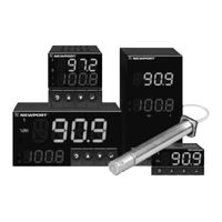
Newport iLD Big Display Operator's Manual (52 pages)
iLD Big Display Universal Temperature & Process Monitor
Brand:
Newport
| Category:
Monitor
| Size: 1.62 MB
Table of Contents
Table of Contents
3
Part 1: Introduction
6
Description
6
Safety Considerations
7
Before You Begin
8
Part 2: Setup
9
Mounting
9
Figure 2.1 Mounting
9
Table 2.1 Front Panel Annunciators
10
Rear Panel Connections
11
Figure 2.2 Rear Panel Power Connector Labels
11
Figure 2.3 Rear Panel Input Connector Labels
11
Table 2.2 Rear Panel Connector
11
Electrical Installation
12
Power Connections
12
Figure 2.4 Main Power Connections
12
Figure 2.5 Inside Cover Rear View
12
Figure 2.6 Thermocouple Wiring Hookup
13
Table 2.3 TC Wire Color Chart
13
Thermocouple - Input Connection
13
Two / Three / Four Wire RTD-Hookups
14
Figure 2.7 Two/Three/Four-Wire RTD A) RTD-1000 Ohm and 500 Ohm Wiring Hookup
14
B) RTD-100 Ohm Wiring Hookup
14
Process Current - Wiring Hookup
15
Process Voltage - Wiring Hookup
15
Figure 2.8 Process Current Wiring Hookup (Internal and External Excitation)
15
Figure 2.9 Process Voltage Wiring Hookup A) Without Sensor Excitation
15
B) with Sensor Excitation
15
Communication Output - Wiring Hookup
16
Figure 2.10 Communication Output: A) RS-232 Output - Wiring Hookup
16
B) RS-485 Output - Wiring Hookup
16
Part 3: Operation: Configuration Mode
17
Introduction
17
Table 3.1 Button Function in Configuration Mode
17
Menu Configuration
18
Figure 3.1 Flow Chart for ID and Setpoints
18
ID Number
19
Setpoints
20
Configuration Menu
21
Figure 3.2 Flow Chart for Configuration Menu
21
Figure 3.3 Flow Chart for Input Type Menu
21
Input Type (Thermocouple)
22
Input Type (RTD)
23
Input Type (Process)
24
Input Type Menu
21
Figure 3.4 Flow Chart for Reading Configuration
24
Reading Configuration Menu
24
Table 3.2 Conversion Table
27
Alarm 1 Menu
28
Figure 3.5 Flow Chart for Alarm 1
28
Alarm 2 Menu
32
Figure 3.6 Flow Chart for Alarm 2
32
Figure 3.7 Flow Chart for Reading Adjust Menu
33
Reading Adjust Menu
33
Figure 3.8 Flow Chart for Setpoint Deviation Menu / Field Calibration
34
Setpoint Deviation Menu / Field Calibration
34
Figure 3.9 Flow Chart for ID Code
35
ID Code Menu
35
Figure 3.10 Flow Chart for Communication Option
37
Communication Options Menu
38
Display Color Selection Menu
43
Figure 3.11 Flow Chart for Display Color Selection
43
Part 4: Specifications
46
Table 4.1 Input Properties
48
Table 5.1 Factory Preset Values
49
Part 5: Factory Preset Values
49
Ce Approval Information
50
Advertisement
Advertisement
Related Products
Newport iDRA Controller DIN Rail Temperature/Process with Isolated Analog Output iSeries
Newport i8-AL
Newport i16-AL
Newport i32-AL
Newport iSeries
Newport iServer MicroServer EIS-PCB
Newport IMS400CCHA
Newport IMS600CC
Newport IMS600CCHA
Newport IDL165-LM Series
Newport Categories
Controller
Measuring Instruments
Receiver
Industrial Equipment
Power Supply
More Newport Manuals
Login
Sign In
OR
Sign in with Facebook
Sign in with Google
Upload manual
Upload from disk
Upload from URL