Sign In
Upload
Manuals
Brands
Newman Manuals
Lathe
EPR Series
Newman EPR Series Manuals
Manuals and User Guides for Newman EPR Series. We have
1
Newman EPR Series manual available for free PDF download: Service Manual
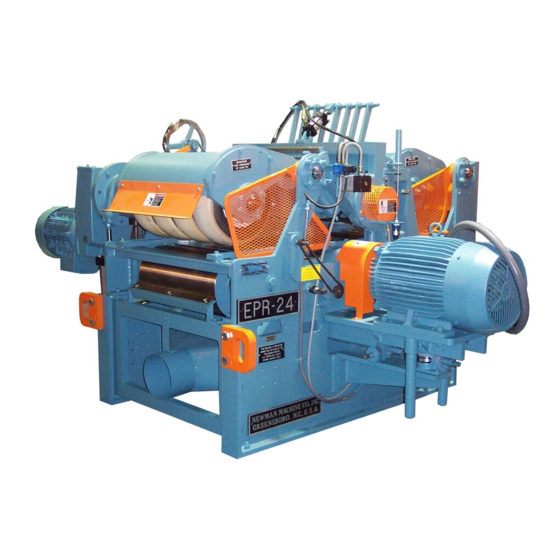
Newman EPR Series Service Manual (214 pages)
Electric Drive Double Roughing Planer. Equipped with Helical Carbide Cutterheads
Brand:
Newman
| Category:
Lathe
| Size: 11 MB
Table of Contents
This Page Intentionally Left Blank
4
Table of Contents
4
1 General Information
10
Warranty
10
Safety Practices
12
Basic Safety Procedures
14
Safe Operating Practices
15
Lumber Jams
16
Receiving
17
Checking Shipment
17
Cleaning
17
Extended Storage
17
Unloading
17
Installing the Planer
19
Foundation
19
Figure 1.5.1-A Foundation Plan: EPR-18 with Anti-Lap
20
Figure 1.5.1-B Foundation Plan: EPR-18 with Anti-Kickback
21
Figure 1.5.1-C Foundation Plan: EPR-18 with Machine Enclosure
22
Figure 1.5.1-D Foundation Plan: EPR-24 with Anti-Lap
23
Figure 1.5.1-E Foundation Plan: EPR-24 with Anti-Kickback
24
Figure 1.5.1-F Foundation Plan: EPR-24 with Machine Enclosure
25
Accessory Equipment
26
Figure 1.5.2-A Alignment of Infeed Conveyor
26
Figure 1.5.2-B Alignment of Outfeed Conveyor
27
Figure 1.5.2-C Alignment of Outfeed Pinch Roll
27
Care of Electrical Equipment
28
Electrical
28
Electrical Requirements
28
Compressed Air Requirements
29
Dust Collection Requirements
29
Start-Up Procedures
30
2 Theory of Operation
31
Planer Description
31
Automatic Cut Control
32
Controls
33
Figure 2.3.1-A Operator's Console
33
Operator's Console
33
Feeder Console (Optional)
36
Figure 2.3.2-A Feeder Console
36
Planer Adjustments
37
Figure 2.4.1-A Left Side Adjustments
37
Mechanical Adjustments
37
Figure 2.4.1-B Bottom Infeed Rolls and Air Valve Panel
38
Figure 2.4.1-C Pneumatic Pressure Bar Adjustments
38
Figure 2.4.1-D Anti-Lap Adjustments
39
Figure 2.4.1-E Right Side Adjustments
40
Figure 2.4.1-F Top Head Limit Stops
41
Figure 2.4.1-G Chipbreaker Adjustments
41
3 Planer Maintenance
43
Planer Lubrication
44
Lubrication Schedule
44
Figure 3.1.2-A Left Side Lubrication Points #1
45
Lubrication Points
45
Figure 3.1.2-B Infeed Lubrication Points
46
Figure 3.1.2-C Chipbreaker Lubrication Points
46
Figure 3.1.2-D Bottom Head Jackscrew and Roll-Out Bearing
47
Figure 3.1.2-E Eurodrive Gearbox
47
Figure 3.1.2-F Right Side Lubrication
48
Preventive Maintenance Schedule
50
Machine Alignment Procedures
51
Bedline Alignment Procedure
51
Figure 3.3.1-A Bedline Alignment Diagram
51
Figure 3.3.2-A Top Head Leveling Adjustments
55
Leveling the Top Head Assembly
55
Figure 3.3.2-B Pressure Bar Leveling Adjustments
57
Aligning the Pressure Bar
58
Figure 3.3.3-A Placement of Straight Edges
59
Figure 3.3.3-B Relationship of Pressure Bar to Straight Edges
59
Figure 3.3.3-C Pressure Bar Alignment Adjustments
60
Figure 3.3.3-D Pressure Bar Actuator Adjustments
62
Figure 3.3.4-A Chipbreaker Adjustments
63
Setting the Chipbreakers
63
Leveling the Bottom Cutterhead
65
Figure 4-A Placement of Straight Edges
65
Figure 4-B Bottom Head Level and Height Adjustments
66
Aligning the Anti-Lap Assembly
67
Figure 4.1.1-A Anti-Lap Adjustments
68
Figure 4.1.1-B Anti-Lap Leaf Spring Adjustment
68
Adjusting Feedroll Reversing Time Delay
69
Adjusting the Anti-Kickback Assembly
69
Figure 4.1.3-A Proscale Controls
70
Zeroing the Proscale
70
Machine Wear and Maintenance Procedures
72
Equipped Incline Table Plates
73
Incline Table Insert Wear
73
Solid Incline Table Plates
73
Figure 4.2.1-A Solid Incline Table Insert Wear
74
Figure 4.2.1-B A.C.C Incline Table Insert Wear
74
Figure 4.2.1-C Relationship of Incline Table Plate to A.C.C. Fingers
74
Removing the Incline Table Insert Plate
75
Automatic Cut Control™ Fingers
76
Figure 4.2.2-A Automatic Cut Control Wear
76
Checking for Chipbreaker Toe Wear
78
Chipbreaker Wear and Replacement
78
Figure 4.2.3-A Chipbreaker Toe Plate Wear
78
To Remove Chipbreaker Toe Plates
78
Figure 4.2.3.2-B Chipbreaker Cutaway
79
Figure 4.2.3-C Chipbreaker Assembly
80
Removing the Chipbreaker
80
Set Reference for Bedline Zero
82
Replacing the Top Head Raising Screw and Worm Gear
84
Cutterhead Bearings
87
General Information for Replacing Ball Bearings
87
Top Cutterhead Bearing Replacement
88
Bottom Cutterhead Bearing Replacement
90
Pneumatic Feedroll Tires
92
Pneumatic System
93
Locally Manufactured Pneumatic Hoses
96
4 Planer Operation
98
Planer Safety
98
Maintaining Machine Guards
98
Personal Safety Equipment
98
Planer Safety Devices
98
Safety Practices
99
Avoiding Contact with a Rotating Cutterhead
100
Avoiding Feed-Roll Pinch Points
100
Avoiding Lumber Ejection or 'Kickback
100
Safety Considerations While Clearing a Jam
100
Clearing a Jam
101
Operating the Planer
102
Setting the Bottom Cutterhead Cut (with Automatic Cut Control™)
102
Setting the Depth of Cut
102
Setting the Top Cutterhead
102
Setting the Bottom Cutterhead Cut (Without Automatic Cut Control™)
103
Setting the Feedroll Height
103
Setting the Anti-Lap
104
Planer Hints
105
5 Helical Carbide Cutterhead Maintenance
107
General Information
107
Maintenance Information
107
Glossary
109
Grinder Maintenance
114
Grinder General Information
114
Grinder Setup and Alignment
115
Installing and Aligning the Bottom Head Grinder Rail
117
General Information
120
Jointing the Bottom Cutterhead
120
Normal Jointing and Regrinding Procedures
120
Jointing the Top Cutterhead
122
Grinder Installation and Setup
124
Preparation for Grinding
124
Setting the Grinding Angle
124
Grinding the Bottom Cutterhead
127
Grinding the Cutterhead Knives
127
Grinding the Top Cutterhead
129
Installing New Knives
132
Grinding New Knives
132
Installing New Knives
133
Cutterhead Maintenance
135
Chipped Knives
135
Refreshing the Clearance Angle
136
Replacing Broken Knives
136
Checking the Cutterhead Knife Height
137
Calibrating an Impact Driver
139
6 Illustrated Parts Breakdown
140
Ordering Repair Parts
140
Table of Contents
141
Anti-Lap with Handwheel Adjustment
143
Anti-Kickback Assembly
145
Pneumatic Valve Panel
148
Infeed, Left Side
151
Infeed, Right Side
154
Chipbreaker Assembly (EPR-18 and EPR-24 Prior to SN 15215)
164
Top Cutterhead Assembly
167
Top Head Raising Assembly
170
Top Head Power Hoist
171
Pressure Bar Assembly
173
Outfeed Section
184
7 Appendixes
198
P5 Parameters
198
P5+ Parameters
200
Sew-Eurodrive Parts List for Epr-18
202
NORD Parts List for EPR-18
205
Sew-Eurodrive Parts List for Epr-24
207
NORD Parts List for EPR-24
210
Material Safety Data Sheets (Information Only)
212
Advertisement
Advertisement
Related Products
Newman EPR-18
Newman EPR-24
Newman Easedale 5 SE
Newman Categories
Indoor Fireplace
Stove
Label Maker
Planer
Lathe
More Newman Manuals
Login
Sign In
OR
Sign in with Facebook
Sign in with Google
Upload manual
Upload from disk
Upload from URL