
Subscribe to Our Youtube Channel
Summary of Contents for Newman EPR Series
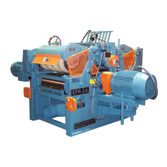
- Page 1 ERVICE ANUAL EPR Series Electric Drive Double Roughing Planer Equipped with Helical Carbide Cutterheads Edition 1.4 Issued 9/12/2000 NEWMAN QUALITY WOODWORKING MACHINERY SINCE 1906...
- Page 2 EPR-18 and EPR-24 Helical Carbide Double Roughing Planer Service and Parts Manual Version 1.4...
- Page 3 This Page Intentionally Left Blank...
-
Page 4: Table Of Contents
Table of Contents GENERAL INFORMATION....................1 Warranty ......................... 1 Safety Practices....................... 3 Basic Safety Procedures....................5 1.3.1 Safe Operating Practices ..................6 1.3.2 Lumber Jams......................7 Receiving ........................8 1.4.1 Unloading........................ 8 1.4.2 Checking Shipment....................8 1.4.3 Cleaning ........................8 1.4.4 Extended Storage .................... - Page 5 3.5.1 Incline Table Insert Wear ...................64 3.5.1.1 Solid Incline Table Plates ……………………………………………………..64 3.5.1.2 A.C.C Equipped Incline Table Plates …………………………………………64 3.5.1.3 Removing The Incline Table Insert Plate ............66 3.5.2 Automatic Cut Control™ Fingers ..............67 3.5.3 Chipbreaker Wear and Replacement ..............69 3.5.3.1 Checking For Chipbreaker Toe Wear .............
- Page 6 5.5.1 General Information.................... 111 5.5.2 Jointing The Bottom Cutterhead................. 111 5.5.3 Jointing The Top Cutterhead ................113 5.5.4 Grinder Installation and Setup ................115 5.5.4.1 Preparation for Grinding ................. 115 5.5.4.2 Setting the Grinding Angle ................115 5.5.5 Grinding The Cutterhead Knives ................ 118 5.5.5.1 Grinding the Bottom Cutterhead..............
- Page 7 Table of Figures Figure 1.5.1-A Foundation Plan: EPR-18 With Anti-Lap ............11 Figure 1.5.1-B Foundation Plan: EPR-18 With Anti-Kickback ........... 12 Figure 1.5.1-C Foundation Plan: EPR-18 With Machine Enclosure ..........13 Figure 1.5.1-D Foundation Plan: EPR-24 With Anti-Lap ............14 Figure 1.5.1-E Foundation Plan: EPR-24 With Anti-Kickback ...........
- Page 8 Figure 4.2.4-A Setting Bedline Reference ................. 73 Figure 4.2.5-A Left Side Top Head Raising Gear Assembly ............75 Figure 4.2.8-A Pneumatic Valve Panel ..................86 Figure 4.2.8.1-B Pneumatic Hose Layout .................. 87 Figure 4.2.8.1-C EPR Pneumatic Schematic ................88 Figure 5.2.3-A Handwheel Type Anti-Lap Properly Adjusted ........... 95 Figure 6.4.1-A Helical Carbide Grinder Assembly ..............
- Page 9 This Page Intentionally Left Blank...
-
Page 10: General Information
1 GENERAL INFORMATION 1.1 Warranty Except as otherwise specifically set forth herein, the Seller shall not be bound by representations, promises or inducements by its agents or employees. No course of prior dealings between the Seller and Purchaser and no usage of trade shall be relevant or admissible to, supplement, explain or vary any of the terms of this offer to purchase. - Page 11 (d) Defects in electrical equipment, ball bearings and other components purchased by Seller as complete units for installation in Seller's machines are not warranted herein, but will be replaced or repaired by the Seller in accordance with the warranty or guarantee of the manufacturer or supplier of said devices.
-
Page 12: Safety Practices
1.2 Safety Practices A. Do not operate, adjust or attempt to maintain this machine until: 1. You have been authorized and properly instructed in the skill you are to perform. 2. You have read and understand these instructions. B. Unless you have shut off all power and locked the switch: •... - Page 13 A WARNING looks like the following example, and indicates a potentially hazardous situation which, if not avoided, could result in death or serious injury. WARNING Indicates a potentially hazardous situation which, if not avoided, could result in death or serious injury. A DANGER warning looks like the following example, and indicates an imminently hazardous situation which, if not avoided, will result in death or serious injury.
-
Page 14: Basic Safety Procedures
Basic Safety Procedures Virtually all automated machinery has the potential to cause personal injury. Although the EPR-Series planers are more properly classed as semi-automated, they are not an exception. When the planer is well maintained and safely operated, avoiding injury is easy. The basic safety procedures that apply to automated machines are easily applied to these planers. -
Page 15: Safe Operating Practices
1.3.1 Safe Operating Practices Besides knowing and following the basic safety rules and procedures that must be in force in any industrial area, the planer operator and maintenance technicians must also observe safe rules of planer operation. The experience of the planer operator cannot be replaced in this area. Maintaining Machine Guards: The EPR-Series Planers have two different widths, and they have the same pinch points, cutterheads, and other hazards that are built-in. -
Page 16: Lumber Jams
1.3.2 Lumber Jams Clearing a Jam in the Planer: Jams are a fact of life around a planer, and they can occur at any time. Most accidents involving planers happen during the jam clearing process. The planer operator must pay special attention to his actions during the jam clearing process to prevent an accident. -
Page 17: Receiving
The 72” straight edge is fastened to the shipping platform. Separate the smaller parts as they are checked so there will be no possibility of their being discarded with the packing material. Notify Newman Machine Company, Inc. immediately if there is a shortage. 1.4.3 Cleaning Before shipment all machined parts were coated with a rust preventative compound which may be removed by wiping with kerosene or varsol. - Page 18 If the machine is to be stored for an extended period of time (any length of time longer than 14 days from the ship date), the following steps should be taken: Coat all exposed metal surfaces with a heavy grease or rust preventative compound such as COSMOLINE.
-
Page 19: Installing The Planer
1.5 Installing The Planer Some consideration should be given to the location of the planer prior to installation. Most installations where the planer is replacing another unit go smoothly, the exception being that there is not enough room for the bottom cutterhead to be rolled out. 1.5.1 Foundation The foundation should be per the foundation diagram for the model of machine that was purchased, i.e. -
Page 20: Figure 1.5.1-A Foundation Plan: Epr-18 With Anti-Lap
Figure 1.5.1-A Foundation Plan: EPR-18 With Anti-Lap... -
Page 21: Figure 1.5.1-B Foundation Plan: Epr-18 With Anti-Kickback
Figure 1.5.1-B Foundation Plan: EPR-18 With Anti-Kickback... -
Page 22: Figure 1.5.1-C Foundation Plan: Epr-18 With Machine Enclosure
Figure 1.5.1-C Foundation Plan: EPR-18 With Machine Enclosure... -
Page 23: Figure 1.5.1-D Foundation Plan: Epr-24 With Anti-Lap
Figure 1.5.1-D Foundation Plan: EPR-24 With Anti-Lap... -
Page 24: Figure 1.5.1-E Foundation Plan: Epr-24 With Anti-Kickback
Figure 1.5.1-E Foundation Plan: EPR-24 With Anti-Kickback... -
Page 25: Figure 1.5.1-F Foundation Plan: Epr-24 With Machine Enclosure
Figure 1.5.1-F Foundation Plan: EPR-24 With Machine Enclosure... -
Page 26: Accessory Equipment
1.5.2 Accessory Equipment Accessory lumber handling equipment, such as conveyors and pinch-rolls, need to be properly setup during their installation. The accessory equipment centerline must be in line with the planer centerline, and with the equipment at the other end of the planer. The bedline of the planer will determine the height of the accessory equipment. -
Page 27: Figure 1.5.2-B Alignment Of Outfeed Conveyor
STRAIGHT EDGE CONVEYOR ROLL 1/4" TO 1/2" BELOW STRAIGHT EDGE BOTTOM INFEED ROLLS INCLINE TABLE & A.C.C. CONVEYOR BELT SHOULD NOT BOTTOM CUTTERHEAD CONTACT STRAIGHT EDGE UNTIL LOWERED 5 TURNS OF HANDCRANK APPROXIMATLY 6" FROM END TABLE AFTER BOTTOM HEAD END FRAME BOTTOM OUTFEED ROLL Figure 1.5.2-B Alignment of Outfeed Conveyor... -
Page 28: Electrical
1.5.3 Electrical 1.5.3.1 Electrical Requirements The plant electrical connection to the planer is the customer’s responsibility. Connection to the planer’s main electrical panel is made through the top left-hand corner of the cabinet. The customer must provide a means of disconnecting the electrical power from the planer and locking it out. -
Page 29: Compressed Air Requirements
inside of the main electrical panel cabinet door. The serial number of the machine is required when ordering extra copies of the electrical diagram. The magnetic starters are wired so that if either the top or bottom cutterhead motor stops due to an overload, the other cutterhead motor will also stop. -
Page 30: Start-Up Procedures
The area of the main exhaust duct should be equal to or slightly larger than the sum of the areas of the branch pipes. Elbows or turns in the pipe should have a radius in the throat at least equal to or greater than one and one half times the diameter of the pipe. -
Page 31: Theory Of Operation
2 THEORY OF OPERATION 2.1 Planer Description The EPR-Series Planers are electrically driven double roughing planers. The planer accepts lumber at its’ infeed, lines it up with the cutterheads, and feeds the lumber through the cutterhead section. The cutterheads remove material from the top and bottom surface of the board simultaneously. -
Page 32: Automatic Cut Control
The A.C.C. (Automatic Cut Control) is a sectional, mechanical device designed and developed by Newman*Whitney to offset the fixed bottom head cut found on conventional knife planers, and to provide more equal cut distribution between the top and bottom cutterheads. -
Page 33: Controls
2.3 Controls The operator’s console is connected to the main electrical panel by a 30 foot conduit. This panel contains all of the operator’s electrical controls. (Section 2.3.1) The main electrical panel is connected to the planer by two 18 foot conduits. The remote or feeder console (Optional) is connected to the operator’s console by a 25 foot conduit. - Page 34 Operator’s Console Function Table FEED SPEED INDICATOR - Shows the feed speed of the upper feedrolls in feet per minute. It is active in both forward and reverse. TOP HEAD - Illuminated momentary pushbutton. Starts the top cutterhead motor, and indicates that the starter is in the run mode.
- Page 35 CHIPBREAKER RELEASE - Activates a solenoid valve to operate the chipbreaker release. MAIN/FEEDER - 2 position rotary switch. Only present on machines with remote feeder console option. MAIN - All controls on the operator’s console are active. Only ‘E-STOP’ on feeder console is active.
-
Page 36: Feeder Console (Optional)
2.3.2 Feeder Console (Optional) START FEED REV - FWD EMERG. STOP PRESSURE CHIPBREAKER STOP FEED RELEASE RELEASE BLANK Figure 2.3.2-A Feeder Console Feeder Console Function Table FEED START - Illuminated momentary pushbutton. Starts the upper feedroll motors and indicates that the starter is in the run mode. It will not engage unless both cutterhead motors are running. -
Page 37: Planer Adjustments
2.4 Planer Adjustments 2.4.1 Mechanical Adjustments Figure 2.4.1-A Left Side Adjustments... -
Page 38: Figure 2.4.1-B Bottom Infeed Rolls And Air Valve Panel
Figure 2.4.1-B Bottom Infeed Rolls and Air Valve Panel LENGTH OF STROKE MANUAL RELEASE (YELLOW BUTTON) VERTICAL ADJUSTMENT Figure 2.4.1-C Pneumatic Pressure Bar Adjustments... -
Page 39: Figure 2.4.1-D Anti-Lap Adjustments
Figure 2.4.1-D Anti-Lap Adjustments... -
Page 40: Figure 2.4.1-E Right Side Adjustments
Figure 2.4.1-E Right Side Adjustments... -
Page 41: Figure 2.4.1-F Top Head Limit Stops
32 - DOWN TRAVEL LIMIT 32 - UP TRAVEL LIMIT Figure 2.4.1-F Top Head Limit Stops Figure 2.4.1-G Chipbreaker Adjustments... - Page 42 Mechanical Adjustments Table Top Head Lock - Locks and unlocks top head yoke. Clockwise rotation locks yoke. Counter clockwise rotation unlocks yoke. Top Head Raising Screw Lock, (Left Hand) - locks top head raising screw in position. Used to level top head to incline table. Incline Table Scale.
-
Page 43: Planer Maintenance
3 PLANER MAINTENANCE This section is intended to give the planer operator and maintenance man the knowledge to perform effective preventative maintenance. Lubrication, suggested preventative maintenance schedule, and alignment procedures are in sections 3.1, 3.2, and 3.3. Separate sections on wear and replacement for major components are in section 3.4. Preventative maintenance is maintenance done on a schedule. -
Page 44: Planer Lubrication
3.1 Planer Lubrication 3.1.1 Lubrication Schedule Lubrication is a necessity for increased machine life. Proper lubrication will increase the life of the bearings, various gear assemblies, and slide wear parts and decrease the number of repairs. The following intervals and lubricants (or their equivalents) are recommended. Planer Lubrication Schedule ITEM LUBRICANT... -
Page 45: Lubrication Points
3.1.2 Lubrication Points Figure 3.1.2-A Left Side Lubrication Points #1... -
Page 46: Figure 3.1.2-B Infeed Lubrication Points
Figure 3.1.2-B Infeed Lubrication Points DETAIL 17 - CHIPBREAKER LUBRICATION Figure 3.1.2-C Chipbreaker Lubrication Points... -
Page 47: Figure 3.1.2-D Bottom Head Jackscrew And Roll-Out Bearing
Figure 3.1.2-D Bottom Head Jackscrew and Roll-Out Bearing Figure 3.1.2-E Eurodrive Gearbox... -
Page 48: Figure 3.1.2-F Right Side Lubrication
Figure 3.1.2-F Right Side Lubrication... - Page 49 Planer Lubrication Points Table Top cutterhead bearing. Infeed roll bearing. Infeed roll pivot shaft bearing. Top head raising shaft bearing. Upper incline table slide. Top head power hoist drive chain. Top head hoist gearmotor. Top head raising gear assembly. Bottom head raising jackscrew. 10.
-
Page 50: Preventive Maintenance Schedule
3.2 Preventive Maintenance Schedule This schedule is recommended by the Newman Machine Company Engineering. It does not include the cutterhead knives. Lubrication of the machine is covered in a separate schedule. ITEM ACTION SCHEDULE Clean area around top head Remove dust, chips, and shavings... -
Page 51: Machine Alignment Procedures
3.3 Machine Alignment Procedures 3.3.1 Bedline Alignment Procedure Figure 3.3.1-A Bedline Alignment Diagram... - Page 52 The table after bottom head is used as the reference point for making all height and alignment adjustments. Refer to Figure 3.3.1-A. CAUTION Remove the main electrical power from the planer after Step 1. Restore main electrical power only after the maintenance action is complete.
- Page 53 Check the 2nd infeed roll. It should be 0.0015” tight to the straight edge. If it is not, use the square head screws at the end of the roll to adjust the roll height up or down (Adjustment 19). Check the 3rd infeed roll. It should be 0.0015” tight to the straight edge. If it is not, use the square head screws at the end of the roll to adjust the roll height up or down (Adjustment 19).
- Page 54 Check each chipbreaker assembly. The resistance as the block is pushed under the toes should be the same for all chipbreakers. • See section 3.3.4 for adjustment. • Pay attention to excessive loss motion in pins and links so as to always have spring tension when chipbreaker yields.
-
Page 55: Leveling The Top Head Assembly
3.3.2 Leveling The Top Head Assembly Stop the planer and lock out the cutterheads and feed system. Unlock and raise the top cutterhead to approximately 6 inches. Raise the upper feedrolls and brace them in the raised position. CAUTION Remove the main electrical power from the planer after Step 1. - Page 56 Place the wooden top head setting block underneath the top head assembly so that the block is lengthwise to the cutterhead and chipbreakers. The block should be in between the cutterhead and chipbreakers. • Slowly lower the top head assembly until the block will not slide underneath the cutterhead.
-
Page 57: Figure 3.3.2-B Pressure Bar Leveling Adjustments
TO CHECK THE ALIGNMENT OF THE PRESSURE BAR TO THE TOP CUTTERHEAD: This procedure is a continuation from step 12 of leveling the top cutterhead. Gently pull the block towards the outfeed of the planer. It should just barely start to go underneath the toe of the pressure bar. -
Page 58: Aligning The Pressure Bar
The following instructions are intended to enable the maintenance personnel to adjust and set the pressure bar on an EPR Series Double Roughing Planer. The illustrations are simplified pictures of specific portions of the planer mechanism and are intended only to clarify the adjustment points mentioned. -
Page 59: Figure 3.3.3-A Placement Of Straight Edges
Figure 3.3.3-A Placement Of Straight Edges Run the top head down using the hand crank until the front edge of the pressure bar just touches the front top side of the straight edge, and the rear side of the pressure bar is .008" above the straight edge (Figure 3.3.3.B). -
Page 60: Figure 3.3.3-C Pressure Bar Alignment Adjustments
If the pressure bar plate has been removed from the pressure bar slide, tighten the pressure bar tension screws until a moderate pressure is felt on the wrench. The lock-washer will not be completely compressed by the screw head. This allows the lock-washer to act as a spring. - Page 61 10. The amount of downward pressure exerted by the pressure bar on the wood can be controlled by adjusting the setscrews on the pneumatic actuator or the manual actuator. If your machine has an air-operated pressure bar, refer to paragraph 10.a and figure 3.3.3.D (a).
-
Page 62: Figure 3.3.3-D Pressure Bar Actuator Adjustments
Figure 3.3.3-D Pressure Bar Actuator Adjustments If the pressure bar plate or pressure bar slide has been removed, make the following adjustments. Otherwise, these screws have been set at the factory and will not require adjustment. • Adjust the two pressure bar spring tension setscrews (Figure 3.3.3.C) to the full up position (until the spring is fully compressed and the screw does not turn). -
Page 63: Setting The Chipbreakers
3.3.4 Setting the Chipbreakers Stop the planer and lock out the cutterheads and feed system. Unlock and raise the top cutterhead to approximately 6 inches. Raise the upper feedrolls and brace them in the raised position. Clean the incline table and table after bottom head using compressed air and a solvent to remove chips and sap build-up. - Page 64 When the force on the top head setup block feels appropriate, lock the jam nut down on the adjustment nut. If slack in the movement of the chipbreaker is evident, adjust the tension of the chipbreaker. The tension adjustment is the two 3/4” nuts below the spring. •...
-
Page 65: Leveling The Bottom Cutterhead
3.4 Leveling the Bottom Cutterhead Stop planer and lock out cutterheads. Unlock and raise top cutterhead to six inches. Disconnect and lock out main power. CAUTION Remove the main electrical power from the planer after Step 1. Restore main electrical power only after the maintenance action is complete. -
Page 66: Figure 4-B Bottom Head Level And Height Adjustments
• Raise or lower the incline table until pulling gently on each strip of paper can move the straight edge. Remove the paper. Slowly rotate the bottom cutterhead counter-clockwise by hand until at least one knife has passed underneath each straight edge. •... -
Page 67: Aligning The Anti-Lap Assembly
3.4.1 Aligning The Anti-Lap Assembly Raise the top head to 6". Raise the upper feed rolls and brace them in the raised position. Clean the incline table and table after bottom head using compressed air and a solvent to remove chips and sap build-up. CAUTION Remove the main electrical power from the planer after Step 1. -
Page 68: Figure 4.1.1-A Anti-Lap Adjustments
• To decrease leaf spring tension, loosen the ¾” bolt that holds the leaf spring to the anti- lap bottom gage. 13. Ensure that the jam nut on the ¾” bolt is tightened. 14. Ensure no tools are left in the planer or on the infeed conveyor. Procedure complete. -
Page 69: Adjusting The Anti-Kickback Assembly
3.4.2 Adjusting The Anti-Kickback Assembly 1. Stop planer and lock out cutterheads. Unlock and raise top cutterhead to six inches. Raise upper feedrolls and brace them in the raised position. Lock out cutterhead and feed starters at the main control panel. Clean the anti-kickback table, anti-kickback finger assembly, and infeed roll area using compressed air to remove chips. -
Page 70: Zeroing The Proscale
3.4.3 Zeroing The ProScale The ProScale is an electronic measuring instrument that is used to measure the distance from bedline zero to the bottom of the top cutterhead cutting circle. The ProScale can display this distance in sixteenths (1/16), thirty-seconds (1/32), sixty-fourths (1/64), millimeters, or thousandths of an inch. - Page 71 Run a board through the planer, and measure the thickness of the board. This is the true height of the top cutterhead. Use the Set Plus (+) or Set Minus (-) button to increment the ProScale display until it agrees with the actual measurement. NOTE When installing a new Proscale, if negative values read, jumper JP3 in the display module must be changed.
-
Page 72: Machine Wear And Maintenance Procedures
3.5 Machine Wear And Maintenance Procedures Various parts of the machine wear faster than others, in particular the bedplates and hold- down devices. The hold-down devices are equipped with replaceable wear plates. The following sections deal with determining the amount of wear and how to replace these parts. Wood that is wet or has a large amount of dust and grit accumulation on the surface causes metal surfaces to wear faster than kiln dried wood. -
Page 73: Incline Table Insert Wear
3.5.1 Incline Table Insert Wear The incline table serves as the foundation for the top cutterhead. As the top cutterhead removes wood from the top side of the board, it presses the board downward. The incline table provides an even, stable surface for the cutterhead to work against. Over a period of several years, the lumber wears the surface of the incline table plate away. -
Page 74: Figure 4.2.1-A Solid Incline Table Insert Wear
SOLID INCLINE TABLE INSERT INCLINE TABLE PLATE Figure 3.5.1-A Solid Incline Table Insert Wear AUTOMATIC CUT CONTROL TOES INCLINE TABLE INSERT INCLINE TABLE PLATE Figure 3.5.1-B A.C.C Incline Table Insert Wear 0.010" INCLINE TABLE PLATE A.C.C. TOE SHOWN IN FULL DOWN POSITION INCLINE TABLE Figure 3.5.1-C Relationship of Incline Table Plate to A.C.C. -
Page 75: Removing The Incline Table Insert Plate
3.5.1.3 Removing The Incline Table Insert Plate 1. Stop planer and lock out cutterheads. Unlock and raise top cutterhead to six inches. Raise upper feedrolls and brace them in the raised position. Disconnect and lock out main power. 2. Remove the lumber guide rails. Use care to avoid damaging the cutterhead knives. 3. -
Page 76: Automatic Cut Control™ Fingers
3.5.2 Automatic Cut Control Fingers The Automatic Cut Control fingers are made of hardened steel. As wood passes over them, the contact area is worn away. New fingers will project approximately 5/16” above a new incline table insert. When they have worn down to approximately 1/8”, they should be replaced The fingers should be replaced before they develop a sharp edge. - Page 77 Unlock and roll out the bottom cutterhead. The A.C.C. assembly will tend to fall into the cutterhead area when the screws are removed. Remove the two 1/4” socket head cap screws in each support arm, and remove the A.C.C. assembly from the planer. Loosen the setscrews in the lower side of each support arm.
-
Page 78: Chipbreaker Wear And Replacement
3.5.3 Chipbreaker Wear and Replacement Each chipbreaker section has a hardened steel toe plate. The toe plate wears more rapidly with air-dried or dusty wood than with kiln-dried wood. When the toe plate has worn down to a sharp edge (3.4.3.A), it will tend to dig into lumber when reverse feed is selected. -
Page 79: Figure 4.2.3.2-B Chipbreaker Cutaway
Remove two 3/8” socket head cap screws from inside chipbreaker shoe (3.4.3.B) Remove toe plate. Inspect alignment roll pins. If the pins are in good condition, reuse them. • If toe plate has only been used on one end, reinstall so that unused end is next to cutterhead. -
Page 80: Removing The Chipbreaker
3.5.3.3 Removing The Chipbreaker Toeplate Height Adjustment Shaft Retaining Bolts Chipbreaker Spring Tension Adjustment Spring Rod Retaining Screw Figure 3.5.3-C Chipbreaker Assembly Stop planer and lock out cutterheads. Unlock and raise top cutterhead to six inches. Raise upper feedrolls and brace them in the raised position. Disconnect and lock out main power. Place a piece of cardboard inside of planer infeed section to catch any small parts that may be dropped. - Page 81 Manually adjust the top head assembly so that the upper pivot shaft may be removed. As the shaft is removed, the chipbreaker release levers will come out. Retain the release levers and the spacers from the shaft. CAUTION The chipbreaker sections weigh 23 pounds each and may have very sharp edges due to wear.
-
Page 82: Set Reference For Bedline Zero
3.5.4 Set Reference For Bedline Zero If the table after bottom head plate has been resurfaced, it will be lower than the original setup, and the bedline zero reference point will be changed. Use the following procedure to re- establish the zero reference point for bed-line. Figure 3.5.4-A Setting Bedline Reference NOTE This procedure will result in inaccurate indications if the incline table insert plate... - Page 83 Lower the outfeed roll and infeed rolls below bedline as indicated by the straight edge. Roll the bottom cutterhead out of the machine to gain access to the jackscrews. • The straight edge may need to be held down at the outfeed end so that the straight edge will be flat on the incline table insert plate.
-
Page 84: Replacing The Top Head Raising Screw And Worm Gear
3.5.5 Replacing the Top Head Raising Screw and Worm Gear Figure 3.5.5-A Left Side Top Head Raising Gear Assembly Over the period of a year, very fine wood dust will enter the top head raising mechanism gear cavity. On an annual basis, the cavity should be cleaned out and filled with fresh grease. This will prolong the life of the brass worm gear. - Page 85 Stop planer and lock out cutterheads. Unlock and raise top cutterhead to six inches. Raise upper feedrolls and brace them in the raised position. Disconnect and lock out main power. Disconnect compressed air. Remove top head lock shaft, jam nuts, thrust bearing, and lock collar. Remove top head raising limit switch (if installed).
- Page 86 18. Before assembling screw into gear, coat the screw with grease. Pack the thrust bearing with fresh grease. 19. Ensure that the set screw hole in the motor side screw is facing into the machine. Use a spirit level or other measuring device, across the top of both screws, to ensure that the screws are level.
-
Page 87: Cutterhead Bearings
All cutterhead spindles are equipped with specially manufactured precision ball bearings. Replacement bearings should be of the same type and may be ordered from Newman Machine Company, Inc. For long bearing life it is important that the lubrication instructions are followed as outlined in Section 3.1. -
Page 88: Top Cutterhead Bearing Replacement
It is always preferable to use bearing pullers or bearing drivers when removing or installing bearings. However, these tools are not always available or may not be applicable to a particular situation. When it becomes necessary to install a new bearing without the benefit of an arbor press or bearing driver, installation can be performed with a hammer, but several precautions should be taken. - Page 89 Clean grease and dirt from the bearing and cutterhead shaft. Clean the interior of the bearing housing. Remove the bearing lock nut and lock washer. Use a set of bearing pullers to remove the bearing. NOTE Do not attempt to heat the bearing to remove it from the shaft. This may warp the cutterhead shaft, causing the cutterhead to be unbalanced.
-
Page 90: Bottom Cutterhead Bearing Replacement
Perform a complete alignment. Procedure Complete. 3.5.6.3 Bottom Cutterhead Bearing Replacement Stop planer and lock out cutterheads. Unlock and raise top cutterhead to 6 inches. Disconnect and lock out main power. Disconnect the compressed air connection. Bleed pressure off the planer’s pneumatic system. Remove the brake disc cover, brake caliper, and brake disc. - Page 91 Install the new bearing. Install the lock washer and lock nut, ensuring that one of the tangs on the washer lines up with a slot on the nut. After the nut is tight, bend the tang down into the slot. Using the grease gun and Lubriplate EMB grease, pack the bearing full of grease.
-
Page 92: Pneumatic Feedroll Tires
3.5.7 Pneumatic Feedroll Tires Pressure in the top roll pneumatic tires should always be maintained at 50 to 60 P.S.I. This is important for long tire life. The distance between the bottom of the tires and the top of the infeed and outfeed rolls should be set according to the thickness of the stock being run. If the tires spin on the lumber when in operation, it indicates the tires are set too high. -
Page 93: Pneumatic System
3.5.8 Pneumatic System The Pneumatic systems on the EPR-Series Planers are simple and easy to maintain. Extra contacts on control switches or relays control the pneumatic systems. 80 to 110 P.S.I. of air pressure is required for proper operation of the systems. If plant air pressure falls below 60 P.S.I., the feedroll raising mechanism may not work and the cutterhead brakes may not stop the cutterheads on shutdown. - Page 94 rate. If the drip rate is set high enough to soak the planer frame below the valve block, the rate is set too high and must be decreased. 3. Depending on the options installed either at the factory or on site, the planer may have as many as five solenoid operated valves installed.
- Page 95 Figure 3.5.8-A Pneumatic Valve Panel...
-
Page 96: Locally Manufactured Pneumatic Hoses
3.5.8.1 Locally Manufactured Pneumatic Hoses DESCRIPTION DIAMETER LENGTH Top Head Brake ¼ 68” Air Actuated Pressure Bar Valve Supply ¼ 108” Pressure Bar Valve to Actuator ¼ 12” Bottom Head Brake ¼ 135” Top Head Chipbreaker 125” Roll Raising Cylinder – Up Pressure Supply 50”... - Page 97 Figure 3.5.8.1-C EPR Pneumatic Schematic...
-
Page 98: Planer Operation
4.1.2 Planer Safety Devices Cutterhead Brakes: The cutterhead brakes on the EPR Series Planers were designed to stop the cutterheads after the power is removed from the cutterhead motors. Since the cutterheads can freewheel for up to five minutes, they present a safety hazard. The cutterheads must have stopped rotating before performing maintenance on the planer, or before attempting to clear a jam. -
Page 99: Safety Practices
Unusual Events: Always pay attention to the way the planer operates. Even though all of Newman's machines are built to exacting standards, each machine will have it's own set of quirks. Familiarity with your planer can be an asset to the maintenance effort, thus increasing the safety of the planer. -
Page 100: Safety Considerations While Clearing A Jam
4.1.5 Safety Considerations While Clearing a Jam 4.1.5.1 Avoiding Contact With A Rotating Cutterhead DO NOT reach into the cutterhead areas until you have visually verified that the cutterhead has stopped rotating. There is frequently no audible indication that the cutterhead is still spinning. -
Page 101: Clearing A Jam
4.1.6 Clearing a Jam CLEARING A JAM IN THE EPR-SERIES PLANER WHEN A JAM OCCURS USE THE FOLLOWING STEPS IN ORDER IMMEDIATE ACTION CHECK TO ENSURE THAT THE "UP/RUN/DOWN" SWITCH IS IN THE 'DOWN' POSITION. IF IT IS NOT, MOVE THE SWITCH TO 'DOWN'. If the lumber does not start to feed: ACTUATE THE CHIPBREAKER TO RELEASE PRESSURE ON THE LUMBER. -
Page 102: Operating The Planer
4.2 Operating The Planer Operating an EPR-Series planer is simple enough that one individual can operate it under most circumstances. To run the planer, the following steps must have been accomplished: • Tools, cleaning materials, and trash have been cleared from the machine area, the planer, and infeed and outfeed lumber handling areas. -
Page 103: Setting The Bottom Cutterhead Cut (Without Automatic Cut Control™)
indicator also shows how much cut will be taken with the bottom cutterhead. This distance is not added to or subtracted from the target size set for the top cutterhead. If the incline table is set 1/8 inch below the table after bottom head, this is the maximum amount of cut that can be taken by the bottom cutterhead. -
Page 104: Setting The Anti-Lap
4.2.3 Setting the Anti-Lap The anti-lap gates should be set so that no piece of lumber can feed into the planer in an over-lapped or under-lapped condition. The upper gate must be set so that lumber of the correct size has enough clearance to get through the gates. Typically, the upper gate is set at the lumber thickness plus 1/8 inch to 1/4 inch extra to allow for the occasional piece that is oversized. -
Page 105: Planer Hints
4.3 Planer Hints If clip or snipe appears on front end of board, one or more of the following could cause the trouble: 1. Top head chipbreaker not holding stock down. 2. Bottom head lower than table after bottom head. 3. - Page 106 If stock hesitates or stops in machine, one or more of the following could cause the trouble: 1. Too much pressure on chipbreaker. 2. Pressure bar too tight on stock (can be due to knife wear). 3. Bottom rolls set too low. 4.
-
Page 107: Helical Carbide Cutterhead Maintenance
5 HELICAL CARBIDE CUTTERHEAD MAINTENANCE General Information The Helical Carbide cutterhead was designed specifically to combat the serious noise problem experienced with conventional straight knife cutterheads. As a result, the cutterhead contains a large number of tightly spiraled carbide knife rows. To facilitate manufacturing and provide for economical replacement of damaged knives, the knife rows are formed by carbide tipped sections (inserts) which butt end to end to form a nearly continuous edge. - Page 108 cutterhead receives excessive wear, the inserts in that area should be switched with unworn inserts at regular intervals to maximize life. Because of the many variables involved, such as how many shifts per day, what variety of wood, how many feet of wood per shift, and even feed speed, it is difficult to give an exact interval for when to joint.
-
Page 109: Glossary
Glossary These are some of the terms and definitions that we use when talking about the Helical Carbide cutterhead. HELICAL CARBIDE CUTTERHEAD or CUTTERHEAD - These terms are used interchangeably to mean the spiraled planer cutterhead. The Helical Carbide cutterhead was designed to reduce the high noise level of straight knife type cutterheads. - Page 110 CLEARANCE ANGLE - The angle along which the top surface of the knife is ground. The top surface of the knife is also called the clearance face. The angle is required so that only the cutting edge of the knife contacts the lumber.
- Page 111 turning. It is also used to remove the rounding caused by wear. Jointing is in part a dulling operation and should be held to a minimum. SPARKING - The final step in the grinding procedure, sparking uses the grinder to remove the high spots left on the knives.
- Page 112 DIAL INDICATOR - A dial indicator set is used to check the alignment of the bottom head grinder rail when it is installed on the bottom head yoke; to check the alignment of the top head grinder rail to the top cutterhead body; to check the alignment of the bottom head jointer rail to the bottom cutterhead body;...
- Page 113 JOINTER STONES - Also called honing stones, they are used to provide a fine edge on the knives and to true up the cutting circle from end to end. The longer one is used for the top head, and the shorter one is used for the bottom head. MACHINIST'S LAYOUT DYE or a common BLACK MAGIC MARKER with a wide tip may be used to darken the clearance face of the knives before grinding and before jointing.
-
Page 114: Grinder Maintenance
Grinder Maintenance 5.4.1 Grinder General Information The grinder used on the EPR-Series Planer was designed for the purpose of grinding Helical Carbide cutterheads. It uses a diamond grinding wheel driven by a 110 volt AC motor through a belt system. It mounts on machined and hand scraped rails that are aligned with the cutterhead body to produce the most even grinding process possible. -
Page 115: Grinder Setup And Alignment
one piece on a frame that slides on the grinder rails. A fingerwheel and screw assembly connect to a nut in the slide frame and raises or lowers the motor and grinding wheel assembly. This increases the depth of the grind. The small tick marks on the fingerwheel are for reference only. Each mark is approximately one-thousandth of an inch. - Page 116 The grinder may be stored with the wheel installed. To protect the wheel and follower finger a rail should be constructed to store the grinder on. Before storing the grinder, it should be blown off in general, and the motor housing in particular should be blown out. Now carefully place the grinder on the grinder rail.
-
Page 117: Installing And Aligning The Bottom Head Grinder Rail
gauge does not pass between the gib and the rail or the contact areas on the front of the rail and the grinder. Install the rail traversing screw nut on the back of the grinder. Using the handwheel, move the grinder from one side of the rail to the other and back again. If the grinder moves along the rail easily, snug the center screw down, and tighten all three jam nuts. - Page 118 Figure 5.4.3-B Bottom Head Grinder Rail Cleaning The entire machined surface of the pad must be clean of dirt, rust and other deposits. Clean it carefully with solvent and the Scotch-Brite pad. Because of the weight of the rail, have someone help install the rail on the bottom head yoke.
- Page 119 Install the dial indicator on the bolt, positioning it to indicate on the side of the cutterhead. This will allow the rail to be positioned parallel to the long side of the cutterhead and reduce the error along the top of the cutterhead. Place the dial indicator close enough to the cutterhead to give a reading of 0.010”...
-
Page 120: Normal Jointing And Regrinding Procedures
5.5 Normal Jointing And ReGrinding Procedures 5.5.1 General Information After the cutterhead has been in use for a while, usually several weeks, the operator will notice a change in the finish or that the planer is having more frequent feed problems or both. This indicates that it is time to joint the cutterheads. - Page 121 5. Install the bottom head jointer guard on the bottom head yoke. Tighten the two bolts securely. 6. Start the bottom cutterhead and let it run for several minutes to warm up the bearings. 7. Using the hand wheel, slowly move the jointer stone completely across the cutterhead.
-
Page 122: Jointing The Top Cutterhead
5.5.3 Jointing The Top Cutterhead 1. Ensure the cutterheads have come to a complete stop. Lock the cutterhead motors out on the operator’s console. CAUTION Although the knives are becoming too dull to plane lumber efficiently, they are still sharp enough to cut the operator’s hand. 2. - Page 123 11. After the cutterhead has stopped spinning, inspect the knives again. This time the joint should show up on all the knife-edges and should look like Fig. 5.5.2-C.. 12. If the joint is very faint in some areas, joint again. This time make only one complete pass.
-
Page 124: Grinder Installation And Setup
5.5.4 Grinder Installation and Setup In general, after the cutterhead has been jointed or honed three times, the land or heel formed by the jointing procedure will be approximately 1/16 of an inch across. When the joint mark is this wide, it is time to regrind the knives. Regrinding should be done only to the extent required to remove the land created by jointing, wear, or nose rounding. - Page 125 • If the mark is to the front of the knife, the grinding wheel must be lowered a small amount to allow it to contact the center of the knife. • When the mark is an even width all the way across the clearance face of the knife, the angle of the grinding wheel to the knife is properly set.
- Page 126 3. The follower finger must be adjusted so that the ball rides in the top third of the gullet during the grinding stroke and so that the follower finger plate contacts the knife body below the edge of the knife during the return stroke. 4.
-
Page 127: Grinding The Cutterhead Knives
the cutterhead until the number 2 gullet is next to the follower finger and mark the cutterhead spindle with a 2. Repeat for all rows. 12. Unhook the grinding weight strap and pass the strap around the cutterhead spindle at the end away from the motor. - Page 128 Figure 5.5.5-B Weight on Top Cutterhead 5. After the grinder has passed over all the knives one time, while the grinder is at the end of the cutterhead, mark the starting point on the grinder fingerwheel indicator ring, and a reference mark on the frame.
-
Page 129: Grinding The Top Cutterhead
8. Move the grinder to the end of the cutterhead opposite the motor and disconnect the screw nut from the back of the grinder. 9. Remove the stone retainer plate from the top head jointer stone holder and install a four inch long 5/16”... - Page 130 off the bluing. Move the grinder to the side, making sure that the grinding wheel does not scrape along the clearance face of the knife. Inspect the mark. 4. If the mark is to the rear of the knife, the grinding wheel must be raised a small amount to allow it to contact the center of the knife.
- Page 131 15. If the mark is good, use the handwheel to move the grinder to the motor end of the cutterhead. Check to see where the follower finger plate contacts the knife. 16. If the follower finger plate touches the knife body on the rake face below the knife-edge, the follower finger is properly adjusted.
-
Page 132: Installing New Knives
5.6 Installing New Knives 5.6.1 Grinding New Knives The following are tips and variations on grinding after a new set of knives has been installed in the cutterhead. Because of manufacturing tolerances and the way that a new knife bit will seat in the knife slot, the clearance face of the bits will vary in height. -
Page 133: Installing New Knives
5.6.2 Installing New Knives To install a new set of knives in the cutterhead you will need the following items: A new set of knife bits. T-Handle torque wrench. A #14 Torx bit and adapter. A ten inch, 3/8 inch extension adapter for the top head. A solution of Fabulene or other strong solvent to remove sap and dust residues from the cutterhead. - Page 134 • As each row is filled, the weight of the bits and screws will cause the cutterhead to turn. Do not let the cutterhead turn by itself with loose knife bits in it. Damage to the bits is possible. Use care in stopping the rotation of the cutterhead by hand since the knife bits are sharp enough to cut you.
-
Page 135: Cutterhead Maintenance
5.7 Cutterhead Maintenance Occasionally, some hard foreign object goes through the planer and chips or even breaks a knife bit. One or two broken bits in the cutterhead will not affect the finish. If there are two or three or more bits that are in line with each other that are broken, then these bits must be moved around to regain the finish. -
Page 136: Replacing Broken Knives
5.7.2 Replacing Broken Knives When a knife bit has been so badly damaged that it needs replacement, follow these steps. 1. Remove the damaged bit from the cutterhead, and discard it. Using a new knife bit and torque screw from the knife maintenance kit, replace it. Darken all the knives with bluing or magic marker. -
Page 137: Checking The Cutterhead Knife Height
5. Now set the height of the grinding wheel so that it just scrapes the clearance face of the knife. Do not worry if the wheel does not cut all the way across the clearance face of the knife. This just confirms that the clearance angle of the knives has changed over the course of several grindings. - Page 138 Repeat this procedure on the other cutterhead. Since the cutterheads do not share a common point of reference during grinding, the height of the knives on one cutterhead may be different from the other cutterhead knives. The second method uses the dial indicator, and is the more accurate method. It is most easily done when checking the accuracy of the grinding operation.
-
Page 139: Calibrating An Impact Driver
5.7.5 Calibrating an Impact Driver Prior to using an impact driver to install knife bits, the driver must be calibrated to deliver a torque of 250 inch/pounds. A pressure reducer must be assembled to control the torque. The pressure reducer consists of a pressure regulator with a male connector on the “IN”... -
Page 140: Illustrated Parts Breakdown
"rear". "Right hand" is always understood to be the observer's right hand as he stands facing the machine at the infeed end. Contact Information To place an order contact: Parts Sales Department Newman Machine Company, Inc. P.O. Box 5467 Greensboro, NC 27435-0467, U.S.A. 2949 Lees Chapel Road Browns Summit,NC 27214,USA E-Mail: sales@newmanwhitney.com... - Page 141 TABLE OF FIGURES Sub-Assembly Page Anti-Lap with Handwheel Adjustment ................ 133 Anti-Kickback Assembly .................... 136 Pneumatic Valve Panel ....................138 Infeed, Left Side ......................141 Infeed, Right Side ....................... 144 Lower Infeed Rolls ...................... 147 Infeed Roll Yoke, EPR-18 and EPR-24 ............... 149 Chipbreaker Assembly (EPR-18 and EPR-24 Prior to SN 15215) ........
- Page 142 FIGURE 1 ANTI-LAP WITH HANDWHEEL ADJUSTMENT...
-
Page 143: Anti-Lap With Handwheel Adjustment
FIG. REF. # PART # NAME NOTES MACHINE EPR-18 NUT, 1"-13 963SK THICK WASHER, 11/16” ID 618UA 47803PP FLANGE STAMPING, #62 MSTR 40571PP BEARING, #RA103RRB2, 1-1/4 1868CM CAM SHAFT, ANTI-LAP ATTACHMENT 1867CM ANTI-LAP GUIDE, BOTTOM, 18" 1870CM WELDMENT, BOTTOM GAUGE ANTI-LAP, 40444PP CAMROL, #CF-1-7/8-S, MCGILL SQUARE HEAD SET SCREW, 1/2"... - Page 144 FIG. REF. # PART # NAME NOTES 4664CM HANDWHEEL, ANTI-LAP ADJUSTMENT 783UA SHAFT, ANTI-LAP ADJUSTMENT 020A * 41378PP SET COLLAR, 3/4" 788UA PLATE, CAM ADJUSTING 789UA BRACKET, CAM ADJUSTING PLATE 784UA NUT, ANTI-LAP TRUNNION 023A * 42772PP RETAINING RING, WALDES #5100-125 48069PP HANDLE ADJUSTABLE STUD TYPE, SIZE 3, #48254...
-
Page 145: Anti-Kickback Assembly
FIGURE 3 ANTI-KICKBACK... - Page 146 FIG. REF. # PART # NAME NOTES MACHINE EPR-18 3205CM TABLE, INFEED, EPR-18 3839CM GUIDE, INFEED TABLE 3027CM FINGER, KICKBACK 41387PP SET COLLAR, 3/4" 3024CM ARM, CYLINDER 41384PP SET COLLAR, 1-1/4" 4012CM SPACER, OUTSIDE 3030CM SPACER 3032CM BRACKET, KICKBACK 3207CM SPACER, RIGHT 3204CM BRACKET, CYLINDER...
- Page 147 FIGURE 4 PNEUMATIC VALVE PANEL...
-
Page 148: Pneumatic Valve Panel
FIG. REF. # PART # NAME NOTES MACHINE EPR-18 56273PP ARO# 104174-4 1/2” SHUTOFF LOCKOUT VALVE 4523CM VALVE PANEL 4522CM COVER, VALVE PANEL 4521CM PLATE, VALVE MOUNTING 56282PP ARO# 29623 BRACKET 48944PP END PLATE, #118803-B, 3/8" NPT, ARO 56281PP ARO# 104173 PANEL NUT 48943PP MANIFOLD, VALVE, #GMP131, 3/8"... - Page 149 FIG. REF. # PART # NAME NOTES 48939PP FILTER/REGULATOR/LUBRICATOR WITH GAUGE, 1/2" NPT PORT SIZE, PIGGYBACK 56272PP MODULAR SPACER KIT, #104167, ARO 46384PP ELBOW, #2103-6-6 PARKER 42394PP MUFFLER 3/8" NPT SCHRADER #4606-0006, NUMATICS #P3MN OR EQUIV. 46549PP FITTING, #0103-6-6 46682PP PARKER #0103-8-6 MALE ADAPTER 1/2"...
- Page 150 FIGURE 5 INFEED, LEFT SIDE...
-
Page 151: Infeed, Left Side
FIG. REF. # PART # NAME NOTES MACHINE EPR-18 3533CM BRACKET, LEFT-HAND, ANTI-LAP 3127CM SHAFT TOP ROLL PIVOT 40586PP BEARING, 1-15/16 RFC, FAFNIR 004 * 41394PP SET COLLAR, 2" 3033CM GUARD, INFEED ROLL 1975CM YOKE, TOP ROLL 1977CM COVER, TOP ROLL YOKE 47809PP BEARING, FAFNIR RFC 2-3/16 CM1143... - Page 152 FIG. REF. # PART # NAME NOTES 4349CM TAB, READOUT CM1371 HOUSING, TOP HEAD BEARING 1192CM COVER, DISC TOP HEAD 1059CM DISC, BRAKE 44949PP CALIPER, BRAKE TOL-O-MATIC #P20DBR-0729 0000 018A* 44680PP REPLACEMENT PUCK 4511CM PLATE, LOCK TOP HEAD 4512CM SCREW, TOP HEAD RAISING L.H. 4514CM TUBE, CHIP CM289...
- Page 153 FIGURE 6 INFEED, RIGHT SIDE...
-
Page 154: Infeed, Right Side
FIG. REF. # PART # NAME NOTES MACHINE EPR-18 4537CM MANIFOLD, AIR CYLINDER 42394PP MUFFLER 3/8" NPT SCHRADER #4606-0006, NUMATICS #P3MN OR EQUIV. 48945PP VALVE, QUICK EXHAUST, #EV-375, 3/8" NPT PORTS, ARO 1241CM PLATE, R.H. WORM COVER 40599PP BEARING, FLANGE, VFTD 3/4”, 3/4” BORE CM1144 STAND, TOP HEAD, R.H. - Page 155 FIG. REF. # PART # NAME NOTES 4554CM BRACKET, LIMIT SWITCH 48219PP TJ ROD CLEVIS #S462-10 3532CM BRACKET, RT. ANTI-LAP(QUAD) 4546CM SAFETY BAR, INFEED 023A* PIN, SAFETY BAR STOP 3166CM MOUNTING BRACKET, ROLL STOP 024A 42409PP HEX JAM NUT, 1"-8 UNC 3747MK STOP, ROLL * ITEM NOT SHOWN...
- Page 156 FIGURE 7 LOWER INFEED ROLL GROUP...
- Page 157 FIG. REF. # PART # NAME NOTES MACHINE EPR-18 3479CM PLATE, QUAD-ROLL INFEED 55600PP 1/2-13 UNC X 2-1/4 LONG SQ. HEAD HALF DOG POINT SET SCREW 47609PP SEALMASTER ST'A' BEARING ER-23 3480CM TUBE, ROLL, 18" 3481CM SHAFT, ROLL 3631CM BRACKET, ROLL ADJUST 1897CM SUPPORT, GUIDE 1899CM...
- Page 158 FIGURE 8 TOP INFEED ROLLS...
- Page 159 FIG. REF. # PART # NAME NOTES MACHINE EPR-18 1977CM COVER, TOP ROLL YOKE 3107CM SPACER WHEEL NO LONGER USED. ORDER PART # CM-3107 47809PP BEARING, FAFNIR RFC 2-3/16 47572PP STUD, WHEEL 1/2-20 X 2-7/8' LONG #610-144 TYPE A 47441PP WHEEL STUD, DOLMAN #610-073 47442PP NUT, DOLMAN #611-016...
- Page 160 FIG. REF. # PART # NAME NOTES 4327CM YOKE, TOP ROLL 94751PP HELICAL GEARMOTOR, FLANGE-MOUNTED: S/N 15119 AND HIGHER #FAF87-DV1 60M4, 15HP, 1800 RPM, REQUIRES 94755PP OUTPUT 90 RPM, 3/60/230-460 VAC; CABLE ADAPTER BUSHING ENTRY NORMAL 015A 92844PP HELICAL GEARMOTOR, 15HP, 1800 RPM: S/N 15118 AND LOWER 3/60/230-460 4452CM 1...
- Page 161 FIGURE 9 CHIPBREAKER ASSEMBLY (EPR-18 AND EPR-24 PRIOR TO SN 15215)
- Page 162 FIGURE 9A CHIPBREAKER ASSEMBLY (EPR-24 SN 15215 AND HIGHER)
- Page 163 FIGURE 9B CHIPBREAKER ASSEMBLY (EPR-18 AND EPR-24 PRIOR TO SN 15215) CHIPBREAKER ASSEMBLY (EPR-24 SN 15215 AND HIGHER)
-
Page 164: Chipbreaker Assembly (Epr-18 And Epr-24 Prior To Sn 15215)
FIG. REF. # PART # NAME NOTES MACHINE EPR-18 84CM SHAFT, HINGE SHORT CM29 SHOE, CHIPBREAKER 27CM PLATE, TOP HEAD CHIPBREAKER TOE 186CM Spacer, Shaft, 1-1/32" ID CM182 LINK, TOP HEAD CHIPBREAKER 116CM HOLDER, SPRING ROD BOTTOM 185CM Spacer, Shaft, 1-5/32" ID CM179 LINK, BOTTOM (CSTG-CM21) 139MF... - Page 165 FIG. REF. # PART # NAME NOTES CHIPBREAKER 4241CM SHAFT HINGE LONG CHIPBREAKER LINK 4240CM SHAFT HINGE LONG CHIPBREAKER LINK 029 * 47598PP SOCKET HEAD SETSCREW, 3/8-16 X 1/2 LG., NYLON PATCH MACHINE EPR-24 (Serial Number 15215 and Higher) 84CM SHAFT, HINGE SHORT CM29 SHOE, CHIPBREAKER...
- Page 166 FIGURE 10 TOP CUTTERHEAD ASSEMBLY...
-
Page 167: Top Cutterhead Assembly
FIG. REF. # PART # NAME NOTES MACHINE EPR-18 1377CM BOLT, 3-1/2” LONG, CHIPBREAKER 14630PP BALL BEARING, 6313 YC 782, PRECISION 42514PP LOCKWASHER, BEARING, #W-13 42489-PP LOCKNUT #N-13 1059CM DISC, BRAKE 005A* 44949PP CALIPER, BRAKE TOL-O-MATIC #P20DBR-0729 0000 005B* 44680PP REPLACEMENT PUCK 1192CM COVER, DISC TOP HEAD... - Page 168 FIG. REF. # PART # NAME NOTES 4525CM143 CUTTERHEAD, Helical Carbide, 7" CC, 8 KNIFE, GREEN LUMBER APPLICATION 3527AH 7" CC FULL KNIFE, 15º RAKE ANGLE 43874PP T45 TORX SCREW 5/16-18 X 3/4 SPECIAL STAR, 7/16 LONG NYLON INSERT 4284CM337 CUTTERHEAD, Helical Carbide, MULTI-TOOTH, 7”...
- Page 169 FIGURE 11 TOP HEAD RAISING ASSEMBLY...
-
Page 170: Top Head Raising Assembly
FIG. REF. # PART # NAME NOTES MACHINE EPR-18 CM1238 SUPPORT, TOP HEAD ADJUSTING SHAFT 2064CM SHAFT, TOP HEAD ADJUSTING 40869PP BUSHING, BRONZE, BOST B-1418-8 40600PP BEARING, FLANGE, VF2S114M, 7/8 BORE 1240CM PLATE, L.H. WORM COVER CM1143 STAND, TOP HD, L.H. 4512CM SCREW, TOP HD. -
Page 171: Top Head Power Hoist
FIGURE 11A TOP HEAD POWER HOIST FIG. REF. # PART # QTY. NAME NOTES 40600PP BEARING, FLANGE, VF2S114M, 7/8 BORE 43397PP 15T, 1/2 P. SPROCKET CM1238 SUPPORT, TOP HEAD ADJUSTING SHAFT 4066CM BRACKET, PROXIMITY SWITCH 90086PP PROXIMITY SWITCH 4065CM GUARD, PROXIMITY SWITCH 43398PP 30T, 1/2 P. - Page 172 FIGURE 12 PRESSURE BAR ASSEMBLY...
-
Page 173: Pressure Bar Assembly
FIG. REF. # PART # NAME NOTES MACHINE EPR-18 1928CM PLATE, PRESSURE BAR 1909CM BAR, PRESSURE 002A SQUARE HEAD SET SCREW, 5/8" x 1-1/2" 002B JAM NUT, 5/8" 002C HEX BOLT, 5/8" x 1-3/4", WITH NUT AND WASHER 336MD SCREW, ADJUSTING , ECCENTRIC PRESSURE BAR 4553CM YOKE, TOP HEAD 18”... - Page 174 FIG. REF. # PART # NAME NOTES 55741PP TURN-ACT ROTARY ACTUATOR #122-111-04, 90 DEGREE, DOUBLE VANE ADJUSTABLE 4402CM BRACKET, PRESSURE BAR ACTUATOR 4412CM SHAFT, ECCENTRIC, AIR-OPERATED PRESSURE BAR, 24" 48919PP REXROTH PW67697-1 SOLENOID AIR 43064-PP SPRING, LATCH, PRESSURE BAR LEVER MD-702 LEVER, PRESSURE BAR RELEASE 43981PP...
- Page 175 FIGURE 13 INCLINE TABLE AND AUTOMATIC CUT CONTROL...
- Page 176 FIG. REF. # PART # NAME NOTES MACHINE EPR-18 1946CM PLATE, INCLINE TABLE -18 INCH 1945CM INSERT, INCLINE TABLE - 18 INCH 1948CM SHAFT, TOE PIVOT 6075CM ARM, OUTER LEFT 004A 6074CM ARM, OUTER RIGHT 1741CM ARM, CENTER 3097CM TABLE, INCLINE, 18 INCH MACHINE 1951CM STOP 43422PP...
- Page 177 Incline Table Assembly Incline Table Raising Assembly FIGURE 14 INCLINE TABLE AND INCLINE TABLE RAISING ASSEMBLIES...
- Page 178 FIG. REF. # PART # NAME NOTES MACHINE EPR-18 4533CM SUPPORT, INCLINE TABLE, FIXED GIB 1866CM SUPPORT, INCLINE TABLE SUPERCEDED BY 4533CM 002+ 1895CM BAR, MOUNTING R.H. NOT USED WITH 4533CM 3257CM BRACKET, INCLINE GUIDE SUPPORT 004+* 1892CM GIB, R.H. NOT USED WITH 4533CM 3479CM PLATE, QUAD-ROLL INFEED...
- Page 179 FIGURE 15 BOTTOM CUTTERHEAD AND BOTTOM HEAD RAISING ASSEMBLIES...
- Page 180 FIG. REF. # PART # NAME NOTES MACHINE EPR-18 3064CM BRACKET L.H. 3059CM EXTENSION 44863PP DUFF NORTON #M1802-1-1 24:1 RATIO 3051CM BAR, SUPPORT, BOTTOM HEAD 3874CM BEARING, MICARTA SLIDE, SUPPORT 006 * 45357PP SCREW, BRASS SLOTTED F.H. 1/4-20 UNC-2A X 5/8” LONG 3056CM BASE, BOTTOM HEAD YOKE, EPR-18 1168CM...
- Page 181 FIG. REF. # PART # NAME NOTES 006 * 45357PP SCREW, BRASS SLOTTED F.H. 1/4-20 UNC-2A X 5/8” LONG 4310CM BASE, BOTTOM HEAD YOKE, EPR-24 92851PP ELECTRIC MOTOR, 50 HP, FR326TS, TEFC, 3600RPM, 3/60/230-460 VOLT, (TOSHIBA) 92867PP ELECTRIC MOTOR, 50 HP, FR326TS, TEFC, 3600RPM, 3/60/380 VOLT 44452PP WOODS SK 1-7/8 BORE 1/2 X 1/4...
- Page 182 FIGURE 16 TABLE AFTER BOTTOM HEAD & BOTTOM HEAD LOCK ASSEMBLIES FIG. REF. # PART # QTY. NAME NOTES MACHINE EPR-18 1900CM SUPPORT, TABLE AFTER BOTTOM HEAD 41388PP SET COLLAR, 1-1/2” 1901CM SHAFT, ECCENTRIC LOCK 1902CM PLATE, TABLE AFTER BOTTOM HEAD 255MD LOCK, PLUG, BOTTOM HEAD YOKE 285MD...
- Page 183 FIGURE 17 EPR-18 OUTFEED SECTION...
-
Page 184: Outfeed Section
FIG. REF. # PART # NAME NOTES MACHINE EPR-18 44820-PP RIM, TIRE, STANDARD SUPERCEDED BY P/N 46666CM 001A 3109-CM RIM, TIRE, FRONT MODIFICATION SUPERCEDED BY P/N 46666CM 001C * 4666CM RIM, TIRE, UNIVERSAL MODIFICATION QTY. AS REQUIRED PER ROLL 3107CM SPACER WHEEL NO LONGER USED. - Page 185 FIGURE 18 EPR-24 OUTFEED SECTION...
- Page 186 FIG. REF. # PART # NAME NOTES MACHINE EPR-24 44820-PP RIM, TIRE, STANDARD SUPERCEDED BY P/N 46666CM 001A 3109-CM RIM, TIRE, FRONT MODIFICATION SUPERCEDED BY P/N 46666CM 001B 3111-CM RIM, TIRE, BACK MODIFICATION SUPERCEDED BY P/N 46666CM 001C * 4666CM RIM, TIRE, UNIVERSAL MODIFICATION QTY.
- Page 187 FIGURE 19 GUARDS...
- Page 188 Figure 19 Continued FIG. REF. # PART # NAME NOTES 3033CM GUARD, INFEED, LEFT SIDE USED ON EPR-18 and EPR-24 3005CM COVER, CHAIN USED ON EPR-18 and EPR-24 4065CM COVER, PROXIMITY SWITCH USED ON EPR-18 and EPR-24 3159CM COVER, BOTTOM HEAD COUPLING USED ON EPR-18 and EPR-24 1192CM COVER, DISK, TOP HEAD...
- Page 189 6/6A 5/5A 4/4A 3/3A 2/2A 1/1A 8/8A 9/9A 16/16A 11/11A FIGURE 20 MAIN ELECTRICAL ENCLOSURE...
- Page 190 FIG. REF. # PART # NAME NOTES MACHINE EPR-18 93518PP FUSE HOLDER, TAYLOR #60308 001A 91156PP FUSE, DUAL ELEMENT, #TRS20R 93518PP FUSE HOLDER, TAYLOR #60308 002A 91156PP FUSE, DUAL ELEMENT, #TRS20R 90325PP STARTER, NEMA#2 8536-SDO-1 SQ. D 003A 91597PP HEATER ELEMENT, B50, SQ. D 93516PP FUSE HOLDER, TAYLOR #61008 004A...
- Page 191 FIG. REF. # PART # NAME NOTES 003A 91790PP Heater Element, #CC121, SQUARE D 3/60/380V ONLY 93516PP FUSE HOLDER, TAYLOR #61008 004A 91103PP TRS100R TRI-ONIC FUSE 004A 91690PP FUSE, DUAL ELEMENT TRS110R 3/60/380V ONLY 90326PP STARTER, NON-REVERSING MAGNETIC, NEMA #4, #8536-SFO-1, 115V COIL, 3 POLE, 005A 91005PP HEATER ELEMENT, #CC94.0 SQ.
- Page 192 FIGURE 21 HELICAL CARBIDE GRINDER ASSEMBLY...
- Page 193 FIGURE 22 GRINDER AND JOINTER RAIL ASSEMBLIES...
- Page 194 FIG. REF. # PART # NAME NOTES MACHINE EPR-18 W21140 PULLEY, GRINDER 92005PP ELECTRIC MOTOR, 1/2 HP, FR48, 3450RPM, 1/60/115V, #RL1208A(BALDOR) 41975PP BELT, ENDLESS, #6 NITTA, #SG500 X 5/8”WIDE X 30”(INSIDE LENGTH) 33573PP NUT, 1 1/4" SPINDLE 004A * 36549W COLLAR, SPACER(DIAMOND WHEEL) 343GH BRACKET FINGER...
- Page 195 FIG. REF. # PART # NAME NOTES 2050CM END PLATE, RAIL CM4254 RAIL, GRINDER, 24" MACHINE 002A * 40903PP BUSHING, BRONZE, BOSTON B-1014-8 145CM SPROCKET, BOTTOM HD GRINDER 29481W FAN BEARING CM1273 BRACKET, RAIL W36849 HANDWHEEL, 12 INCH 28714PP HANDLE, REVOLVING; BALCRANK 4290CM SCREW, FEED, 24"...
- Page 196 FIG. REF. # PART # NAME NOTES MACHINE EPR-18 & EPR-24 FIG. REF. # PART # QTY NAME NOTES 44345PP EXTENSION, AIR VALVE #442, 1 1/4 25001PP WRENCH, JHW #482 SPANNER 3115CM EDGE, STRAIGHT, 72" 31163PP ALEMITE GUN #1055 K11 3779CM SET-UP BLOCK 410MD...
- Page 197 This Page Intentionally Left Blank...
-
Page 198: Appendixes
7 APPENDIXES 7.1 GPD-505 / P5 Parameters QUICK REFERENCE FOR GPD-505 / P5 PARAMETERS FUNCTION FACTORY USER FUNCTION FACTORY USER NUMBER DEFAULT SETTING NUMBER DEFAULT SETTING no-01 no-36 no-02 no-37 no-03 230.0 460.0 no-38 (460.0V) no-04 no-39 no-05 no-40 no-06 no-41 no-07 no-42... - Page 199 QUICK REFERENCE FOR GPD-505 / P5 PARAMETERS (Part 2) FUNCTION FACTORY USER FUNCTION FACTORY USER NUMBER DEFAULT SETTING NUMBER DEFAULT SETTING no-73 no-95 0.0s Dependant no-74 no-96 Dependant no-75 0.0 HZ no-97 Dependant no-76 2.0 HZ no-98 no-77 no-99 no-78 160% no-100 no-79...
-
Page 200: P5+ Parameters
7.2 P5+ Parameters QUICK REFERENCE FOR P5+ PARAMETERS FUNCTION FACTORY USER FUNCTION FACTORY USER NUMBER DEFAULT SETTING NUMBER DEFAULT SETTING no-01 no-36 no-02 no-37 no-03 230.0 460.0 no-38 (460.0V) no-04 no-39 no-05 no-40 no-06 no-41 no-07 no-42 no-08 no-43 no-09 no-44 no-10 no-45... - Page 201 QUICK REFERENCE FOR P5+ PARAMETERS (Part 2) FUNCTION FACTORY USER FUNCTION FACTORY USER NUMBER DEFAULT SETTING NUMBER DEFAULT SETTING no-73 no-95 no-74 no-96 0.0s no-75 0.0 HZ no-97 no-76 no-98 0.0 HZ no-77 no-99 Dependant no-78 0.0 HZ no-100 no-79 2.0 HZ no-101 no-80...
-
Page 202: Sew-Eurodrive Parts List For Epr-18
Sew-Eurodrive Parts List For Epr-18 Use 2-Gear Stage List... -
Page 205: Nord Parts List For Epr-18
7.4 NORD Parts List for EPR-18... -
Page 207: Sew-Eurodrive Parts List For Epr-24
7.5 Sew-Eurodrive Parts List For Epr-24 Use 2-Gear Stage List... -
Page 210: Nord Parts List For Epr-24
7.6 NORD Parts List for EPR-24... -
Page 212: Material Safety Data Sheets (Information Only)
Contact points for Material Safety Data Sheets are provided in this section for customer information. Newman Machine Company highly recommends that the customer contact the manufacturers of these items to obtain current copies of the Material Safety Data Sheet. If different materials are substituted for Newman’s recommended lubricants and grinding... - Page 213 SUPERABRASIVE GRINDING WHEEL Universal Superabrasives Metal & industrial Grinding Division 130 Wharton Road, Bristol, PA 19007 Information (215) 785-5266...
- Page 214 NEWMAN MACHINE COMPANY, INC. 2949 Lees Chapel Road Browns Summit, North Carolina 27214, USA www.newmanwhitney.com Phone: 336-273-8261 P.O. Box 5467 Fax: 336-272-9920 Greensboro, NC 27435-0467 Sales Fax: 336-273-6939 email: sales@newmanwhitney.com...
Need help?
Do you have a question about the EPR Series and is the answer not in the manual?
Questions and answers