Sign In
Upload
Manuals
Brands
Netberg Manuals
Server
Demos R420 M2
Netberg Demos R420 M2 Manuals
Manuals and User Guides for Netberg Demos R420 M2. We have
1
Netberg Demos R420 M2 manual available for free PDF download: User Manual
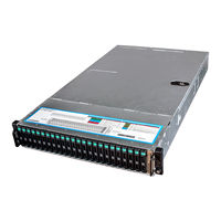
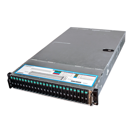
Netberg Demos R420 M2 User Manual (213 pages)
Brand:
Netberg
| Category:
Server
| Size: 11 MB
Table of Contents
Table of Contents
3
1 Safety Information
12
Conventions
13
Acronyms
14
Safety Information
17
Important Safety Instructions
17
Disclaimer
18
2 About the Server
19
Introduction
20
System Features
21
HDD System Front View
21
Major Features
21
Specifications
22
Package Contents
24
A Tour of the System
25
System
25
HDD System Overview
25
Component Overview
25
Component Overview
26
System Front View
27
HDD System Front View
27
System Rear View
28
Back View with Two Nodes (with OCP 1G/10G Base-T NIC)
28
HDD System Front View
28
Buttons and System LED Description
29
Back View with Two Nodes (with OCP SFP+ NIC)
29
System Rear View
29
LED Status Definition
30
Front Panel Buttons and Leds
30
Rear Panel Power Leds
30
HDD LED Definition
31
3 Installing Hardware
32
Safety Measures
33
Top Cover
34
Removing a Top Cover
34
Installing a Top Cover
34
Sliding the Chassis Cover to the Front
35
Power Supply Unit
36
Removing a Power Supply Unit
36
Installing a Power Supply Unit
37
Hard Disk Drives
38
SATA / SAS Hdds
38
Removing a 3.5" Hard Drive Tray
38
SATA / SAS HDD Locations
38
Sliding out the HDD Assembly
38
Installing a 3.5" Hard Drive Tray
39
Removing the HDD
39
Placing the HDD to the HDD Tray
39
SATA / SAS Hdds
40
Fastening the Screws
40
Installing the HDD Assembly
40
Removing a 2.5" Hard Drive Tray
41
SATA / SAS HDD Locations
41
Sliding out the HDD Assembly
41
Installing a 2.5" Hard Drive Tray
42
Removing the HDD
42
Placing the HDD to the HDD Tray
42
Fastening the Screws
42
Installing the HDD Assembly
43
Mainboard Modules
44
Removing a Mainboard Module
44
Node Locations
44
Installing a Mainboard Module
45
Heat Sink
46
To Install the Heat Sink
46
To Remove the Heat Sink
46
Processor
47
To Remove a Processor
47
Lifting the Processor out of the Socket
48
To Install a Processor
49
Memory
50
DDR4 3 Slots Per Channel (SPC) DIMM Population Configuration
50
DDR4 2 Slots Per Channel (SPC) DIMM Population Configuration
51
To Install a DIMM
52
To Remove a DIMM
52
Inserting the DIMM into the Socket
53
Interposer Board
54
Interposer Board Location
54
To Remove the Interposer Board
55
To Install the Interposer Board
56
Expander Board
57
To Remove the Expander Board
57
Removing the Expander Board Assembly
57
To Install the Expander Board
58
Removing the Expander Board
58
Rear HDD Assembly
59
To Install the Rear HDD
59
To Remove the Rear HDD
59
Removing the Rear HDD Assembly
59
Removing the Rear HDD
59
To Remove the Rear HDD Backplane
60
Installing the Rear HDD
60
Installing the Rear HDD Assembly
60
To Install the Rear HDD Backplane
61
Removing the Rear HDD Backplane Bracket
61
Removing the Rear HDD Backplane
61
X16 Riser Card
62
To Remove the Expansion Card
62
Removing the Expansion Card Assembly
62
To Install the Expansion Card
63
To Remove the X16 Riser Card
63
Removing the Expansion Card
63
To Install the X16 Riser Card
64
Fan Duct
65
To Install the Fan Duct
65
To Remove the Fan Duct
65
Removing the Fan Ducts
65
Motherboard
66
To Install the Motherboard
66
To Remove the Motherboard
66
Strong Plate
67
To Remove the Strong Plate
67
To Install the Strong Plate
68
Power Distribution Boards
69
To Remove the Power Distribution Boards
69
Power Distribution Board Locations
69
Removing the Upper Power Distribution Board
70
Removing the Bridge Card
70
To Install the Power Distribution Board
71
Removing the Lower Power Distribution Board
71
System Fans
72
To Install a System Fan
72
To Remove a System Fan
72
To Install the Fan Control Board
73
To Remove the Fan Control Board
73
Removing the Fan Control Board
73
Middle Plane
74
Upper Middle Plane Location
74
To Remove the Middle Planes
75
Removing the Upper Middle Plane
75
To Install the Middle Planes
76
Removing the Lower Middle Plane
76
12X3.5" SATA / SAS HDD Backplane
77
To Remove the Backplane
77
Removing the Screws
78
Removing the HDD Cage
78
To Install the Backplane
79
Removing the Backplane
79
24X2.5" SATA / SAS HDD Backplane
80
To Remove the Backplane
80
Removing the Screws
81
Removing the HDD Cage
81
Removing the Bridge Board
82
Removing the Bridge Board Bracket
82
To Install the Backplane
83
Removing the Backplane
83
HBA Card
84
To Remove the HBA Card
84
To Install the HBA Card
85
Installing the HBA Card
85
OCP Card
86
To Remove the OCP Card
86
To Install the OCP Card
87
Front Panel
88
To Remove the Front Panel
88
Removing the Front Panel Assembly
88
To Install the Front Panel
89
Removing the Front Panel
89
Sensor Board
90
To Remove the Sensor Board of 12 X 3.5" HDD Server
90
To Install the Sensor Board of 12X3.5" HDD Server
91
To Remove the Sensor Board of 24 X 2.5" HDD Server
91
Removing the Sensor Board
91
To Install the Sensor Board of 24 X 2.5" HDD Server
92
4 Connectors
93
Motherboard Connectors
94
Mainboard Overview
95
12 X 3.5" HDD Backplane Connectors
97
12X3.5" HDD Backplane
97
24 X 2.5" HDD Backplane Connectors
98
24X2.5" HDD Backplane
98
Bridge Board Connectors
100
Middle Plane Connectors
101
NIC Middle Plane Connectors
101
Upper Middle Plane Connectors
101
Upper Middle Plane
101
NIC Middle Plane
101
NTB Middle Plane
102
Power Distribution Board Connectors
103
Bridge Board
103
Power Distribution Board
103
Rear HDD Backplane Connectors
104
Rear HDD Backplane
104
Expander Board Connectors
105
Fan Control Board Connectors
106
Fan Control Board
106
Interposer Board Connectors
107
Interposer Board
107
Sensor Board Connectors
108
Sensor Board
108
5 Cable Routing
109
Cable Routing for 12 X 3.5" Hard Drives Configuration
110
Cable Routing for 24 X 2.5" Hard Drives Configuration
111
6 Bios
112
BIOS Setup Utility
113
Entering BIOS Setup
113
Main Features
113
Setup Page
113
BIOS Setup
113
Keyboard Commands
114
Menu Selection Bar
116
Server Platform Setup Utility Screens
116
Main
117
Main Screen
117
Advanced Screen
118
Processor Configuration
119
Advanced Power Management Configuration
121
CPU P State Control
122
CPU C State Control
123
CPU T State Control
124
CPU Advanced PM Tuning
125
Energy Perf BIAS
126
QPI Configuration
127
Memory Configuration
128
Memory Thermal
130
Memory Power Savings Advanced Options
131
Memory RAS Configuration
132
IIO Configuration
133
IIO0 Configuration
134
Socket 0 Pcied00F0-Port0/DMI
135
IIO1 Configuration
136
IOAT Configuration
137
Intel VT for Directed I/O (VT-D)
138
PCH Configuration
139
PCI Express Configuration
140
PCI Express Root Port X
141
PCH SATA Configuration
142
SATA Mode Options
143
USB Configuration
144
Security Configuration
145
Platform Thermal Configuration
146
Server ME Configuration
147
Runtime Error Logging
148
Whea Settings
149
QPI Error Enabling
150
Memory Error Enabling
151
IIO Error Enabling
152
PCI/PCI Error Enabling
153
AST2400 Super IO Configuration
154
Serial Port 1 Configuration
155
Serial Port 2 Configuration
156
Serial Port Console Redirection
157
COM0 Console Redirection Settings
158
COM1 Console Redirection Settings
160
Legacy Console Redirection Settings
162
Console Redirection Settings
163
PCI Subsystem Settings
164
Network Stack Configuration
165
CSM Configuration
166
Trusted Computing
167
USB Configuration
168
Server Management
170
System Event Log
171
View FRU Information
172
BMC Network Configuration
173
Security Menu
174
Boot
175
Save&Exit Menu
177
Utility
179
BIOS Requirements
179
BIOS Requirements Description
179
ROM Flash
180
BIOS Recovery
180
Update ME FW with the Whole Image File under Linux Environment
180
Update under DOS Prompt
180
Update under EFI Shell
180
7 Rail Kit Assembly
182
Unpacking the System
183
Installing the Rails
184
Installing the System into the Rack
185
Tightening the Thumbscrews
186
8 Troubleshooting
187
Server Boot Issue Topics
188
System Does Not Boot after Initial Installation
189
Power Cord Not Plugged in
189
Processor Issues
189
Memory Issues
189
Monitor Issues
189
Power Supply, Chassis and Fan Issues
190
Cable Issues
190
Electrical Short or Overload
190
Defective Components
190
System Does Not Boot after Configuration Changes
191
Hardware Changes
191
Software Changes
191
BIOS Changes
191
Installation Problems
191
Troubleshooting External Connections
192
9 Installation and Assembly Safety Instructions
193
10 Server Safety Information
196
Safety Warnings and Cautions
197
Intended Application Uses
199
Site Selection
200
Equipment Handling Practices
201
Power and Electrical Warnings
202
Power Cord Warnings
203
System Access Warnings
204
Rack Mount Warnings
205
Electrostatic Discharge (ESD)
206
Other Hazards
207
Cooling and Airflow
208
Laser Peripherals or Devices
209
11 Regulatory and Compliance Information
210
Electromagnetic Compatibility Notices
211
FCC Verification Statement (USA)
211
Europe (CE Declaration of Conformity)
211
VCCI (Japan)
212
Regulated Specified Components
212
Restriction of Hazardous Substances (Rohs) Compliance
212
End of Life / Product Recycling
213
Advertisement
Advertisement
Related Products
Netberg Demos R130 M2
Netberg Categories
Switch
Server
Camera Accessories
Storage
More Netberg Manuals
Login
Sign In
OR
Sign in with Facebook
Sign in with Google
Upload manual
Upload from disk
Upload from URL