Table of Contents
Advertisement
Quick Links
Advertisement
Table of Contents
Troubleshooting

Related Manuals for Netberg Demos R420 M2

Summary of Contents for Netberg Demos R420 M2
- Page 1 Netberg Demos R420 M2 server. User manual.
- Page 2 Netberg Demos R420 M2 server. User manual.
-
Page 3: Table Of Contents
Table of Contents 1. Safety Information ......................1 1.1. Conventions ......................2 1.2. Acronyms ........................ 3 1.3. Safety Information ....................6 1.3.1. Important Safety Instructions ................. 6 1.4. Disclaimer ....................... 7 2. About the Server ....................... 8 2.1. Introduction ......................9 2.2. - Page 4 Netberg Demos R420 M2 server. User manual. 3.11.1. To remove the expander board ..............46 3.11.2. To install the expander board ..............47 3.12. Rear HDD Assembly ................... 48 3.12.1. To remove the rear HDD ................48 3.12.2. To install the rear HDD ................48 3.12.3.
- Page 5 Netberg Demos R420 M2 server. User manual. 3.25.4. To install the sensor board of 24 x 2.5” HDD Server ........81 4. Connectors ........................82 4.1. Motherboard Connectors ..................83 4.1.1. 12 x 3.5” HDD Backplane Connectors ............86 4.1.2. 24 x 2.5” HDD Backplane Connectors ............87 4.2.
- Page 6 Netberg Demos R420 M2 server. User manual. 6.3.6.4. SATA Mode Options ..............132 6.3.6.5. USB Configuration ................. 133 6.3.6.6. Security Configuration ..............134 6.3.6.7. Platform Thermal Configuration ............135 6.3.7. Server ME Configuration ................136 6.3.8. Runtime Error Logging ................137 6.3.8.1.
- Page 7 Netberg Demos R420 M2 server. User manual. 8.2.7. Electrical Short or Overload ............... 179 8.2.8. Defective Components ................179 8.3. System does not boot after Configuration Changes ..........180 8.3.1. Hardware Changes ................... 180 8.3.2. Software Changes ..................180 8.3.3. BIOS Changes ..................180 8.3.4.
- Page 8 List of Figures 2.1. 3.5" HDD System Front View ..................10 2.2. 2.5" HDD System Front View ..................10 2.3. 3.5" HDD System Overview ................... 14 2.4. 2.5" HDD System Overview ................... 15 2.5. 3.5" HDD System Front View ..................16 2.6.
- Page 9 Netberg Demos R420 M2 server. User manual. 3.39. Removing the Expander Board ..................47 3.40. Removing the Rear HDD Assembly ................48 3.41. Removing the Rear HDD ..................... 48 3.42. Installing the Rear HDD ....................49 3.43. Installing the Rear HDD Assembly ................49 3.44.
- Page 10 Netberg Demos R420 M2 server. User manual. 4.1. Mainboard Overview ...................... 84 4.2. 12x3.5“ HDD Backplane ....................86 4.3. 24x2.5“ HDD Backplane ....................87 4.4. Bridge Board ......................... 89 4.5. Upper Middle Plane ....................... 90 4.6. NIC Middle Plane ......................90 4.7.
- Page 11 List of Tables 2.1. Major Features ......................10 2.2. Specifications ........................ 11 2.3. Component Overview ....................14 2.4. Component Overview ....................15 2.5. 3.5" HDD System Front View ..................16 2.6. 2.5" HDD System Front View ..................17 2.7. System Rear View ......................17 2.8.
-
Page 12: Safety Information
Chapter 1. Safety Information... -
Page 13: Conventions
Safety Information 1.1. Conventions Several different typographic conventions are used throughout this manual. Refer to the following examples for common usage. Bold type face denotes menu items, buttons and application names. Italic type face denotes references to other sections, and the names of the folders, menus, pro- grams, and files. -
Page 14: Acronyms
Safety Information 1.2. Acronyms Word Definition Analog to Digital ACPI Advanced Configuration and Power Interface Alerting Standard Forum Asserted Active-high (positive true) signals are asserted when in the high electrical state (near power potential). Active-low (negative true) signals are asserted when in the low electrical state (near ground potential). - Page 15 Safety Information Word Definition ICMB Intelligent Chassis Management Bus IERR Internal Error Internet Protocol IPMB Intelligent Platform Management Bus IPMI Intelligent Platform Management Interface In-Target Probe 1024 bytes. Keyboard Controller Style Keyboard, Video, Mouse Local Area Network Liquid Crystal Display Lower Critical Threshold Light Emitting Diode LNCT...
- Page 16 Safety Information Word Definition POST Power-On Self Test Pulse Width Modulation Remote Access Card Random Access Memory RMCP Remote Management Control Protocol Read Only Memory Real-Time Clock. Component of the chipset on the baseboard. RTOS Real Time Operation System Serial Communication Interface SCSI Daughter Card Sensor Data Record SEEPROM...
-
Page 17: Safety Information
Safety Information 1.3. Safety Information 1.3.1. Important Safety Instructions Read all caution and safety statements in this document before performing any of the instructions. Warnings Heed safety instructions: Before working with the server, whether using this manual or any other resource as a reference, pay close attention to the safety instructions. -
Page 18: Disclaimer
Safety Information 1.4. Disclaimer The information in this document is subject to change without notice. The manufacturer makes no representations or warranties with respect to the contents hereof and specifically disclaims any im- plied warranties of merchantability or fitness for any particular purpose. Furthermore, the manufac- turer reserves the right to revise this publication and to make changes from time to time in the con- tent hereof without obligation of the manufacturer to notify any person of such revision or changes. -
Page 19: About The Server
Chapter 2. About the Server... -
Page 20: Introduction
About the Server 2.1. Introduction This document is for the person who installs, administers, and troubleshoots servers and storage systems. Netberg assumes you are qualified in the servicing of computer equipment and trained in recognizing hazards in products with hazardous energy levels. -
Page 21: System Features
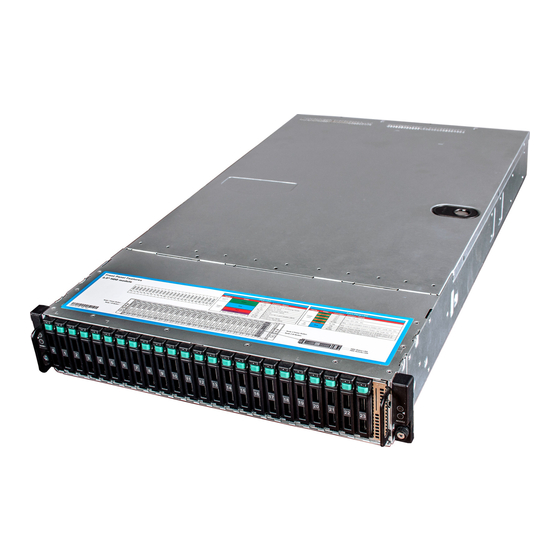
About the Server 2.2. System Features This chapter describes the external features of this server. It includes specific sections that identify these features and specifications. Figure 2.1. 3.5" HDD System Front View Figure 2.2. 2.5" HDD System Front View Table 2.1. Major Features Chassis 2U rack-mounted chassis Power 2 x 1400W redundant AC power supplies Node Supports 2 nodes Front: 12 x 3.5”... -
Page 22: Specifications
About the Server Chassis 2U rack-mounted chassis Rear: 4 x 2.5” SATA 6Gb/s SSDs (2 pieces per node) One 3.5” or 2.5” HDD Front Backplane Backplane Two rear HDD Backplanes (one per node) Number of fan cage: 4 System Fan Single Fan Size: 60mm x 60mm x 38mm Table 2.2. Specifications Form Factor 2 independent nodes in a 2U chassis... - Page 23 About the Server Form Factor 2 independent nodes in a 2U chassis Operating System: +20% ~ +80% Humidity Non-operating System (with package): +10% ~ +90%...
-
Page 24: Package Contents
About the Server 2.3. Package Contents The following list includes the package components: 1 x 2U chassis system 1 x Power cord 1 x Rail kit... -
Page 25: A Tour Of The System
About the Server 2.4. A Tour of the System The following illustrations show the major component parts of these two variants. 2.4.1. System Figure 2.3. 3.5" HDD System Overview Table 2.3. Component Overview Description Power Suply Nodes Power Distribution Boards FCB (Fan Control Board) Strong Plate Middle Plane 12x3.5”... -
Page 26: Component Overview
About the Server Description Front Panel 1 3.5” HDD Bays System Fans Interposers Expansion boards Figure 2.4. 2.5" HDD System Overview Table 2.4. Component Overview Description Power Suply Nodes Power Distribution Boards FCB (Fan Control Board) Strong Plate Middle Planes (Upper and Lower) Bridge Board... -
Page 27: System Front View
About the Server Description Front Panel 2 Front Panel 1 2.5” HDD Bays 24x2.5” HDD Backplane System Fans Interposers Expansion boards 2.4.2. System Front View The system supports up to 12 x 3.5” or 24 x 2.5” HDD configurations. The front view of this 2U server allows easy access to HDDs. -
Page 28: System Rear View
About the Server Table 2.6. 2.5" HDD System Front View Description Front Panel 1 HDD Activity LED HDD Status LED HDDs Dummy HDD/SSD Front Panel 2 2.4.3. System Rear View The server back view includes the connectors of the external system devices. Figure 2.7. Back View with Two Nodes (with OCP 1G/10G Base-T NIC) Table 2.7. System Rear View Description... -
Page 29: Buttons And System Led Description
About the Server Description System Health LED Figure 2.8. Back View with Two Nodes (with OCP SFP+ NIC) Table 2.8. System Rear View Description Power Supply 2 Power Supply 1 Rear Dual USB Port 10G NIC 1 port SAS External Port 1 BMC Reset Button SAS External Port 0 VGA Connector Dual SSD OS Disks... -
Page 30: Led Status Definition
About the Server Figure 2.9. 3.5" Front Panel Buttons and LEDs Figure 2.10. 2.5" Front Panel Buttons and LEDs Table 2.9. Front Panel Buttons and LEDs Description ID Button for Node 1 Power Button for Node 1 ID Button for Node 2 Power Button for Node 2 The back view LED information displays details regarding the AC power LED. -
Page 31: Hdd Led Definition
About the Server Table 2.11. HDD LED Definition Name Color Condtion Description Activity Green HDD ready for access Blink During spin up or accessing HDDs HDD not ready Status Blue Ready for remove (SES) Blink HDD Identifier (SES) Normal Hard drive fail or port disable (SES) Mormal Purple Blink... -
Page 32: Installing Hardware
Chapter 3. Installing Hardware... -
Page 33: Safety Measures
Installing Hardware 3.1. Safety Measures Always ask for assistance to move or lift the system. Only perform troubleshooting as authorized by the product documentation, or as di- rected by a service and support team. Repairs not authorized by warranty may void the warranty and damage the system. -
Page 34: Top Cover
Installing Hardware 3.2. Top Cover 3.2.1. Removing a Top Cover ENSURE ALL POWER IS DISCONNECTED FROM THE SYSTEM BEFORE PRO- CEEDING. 1. Release the screw on the chassis cover. 2. Press the button along the direction of the arrow. 3. Simultaneously slide the cover horizontally to the back and remove it. Figure 3.1. Removing Top Cover 3.2.2. -
Page 35: Sliding The Chassis Cover To The Front
Installing Hardware Figure 3.2. Sliding the Chassis Cover to the Front 2. Secure the chassis cover with one screw. Figure 3.3. Installing Screws This system must be operated with the chassis cover installed to ensure proper cool- ing. -
Page 36: Power Supply Unit
Installing Hardware 3.3. Power Supply Unit This server is designed with two 1400W power supplies. When the server is equipped with dual power supply, the hot-swappable redundant function is provided. If one power supply does not work, you can replace the failed power supply without powering off the server, because the other one can take the place of the failed one. -
Page 37: Installing A Power Supply Unit
Installing Hardware Figure 3.5. Removing the Power Supply 3.3.2. Installing a Power Supply Unit Figure 3.6. Installing a Power Supply Unit Insert the replacement power supply firmly into the bay. The retaining clip should snap. Connect the AC power cord to the replacement power supply. -
Page 38: Hard Disk Drives
Installing Hardware 3.4. Hard Disk Drives Do not operate the system without all hard drive trays inserted into the chassis. All hard drive bays must be occupied by either a hard drive or an empty hard drive tray. Hard drives may be removed while the system is operational but should be immediate- ly replaced by another hard drive or an empty hard drive tray. -
Page 39: Installing A 3.5" Hard Drive Tray
Installing Hardware 4. Loosen the four screws that secure the HDD. 5. Lift the HDD out of the HDD tray. Figure 3.9. Removing the HDD 3.4.3. Installing a 3.5” Hard Drive tray Do not force the tray handle closed. If resistance is encountered, check the hard drive is properly inserted and the hard drives on either side are properly inserted. -
Page 40: Sata / Sas Hdds
Installing Hardware Figure 3.11. Fastening the Screws 3. Carefully insert the HDD assembly into the HDD bay with the lever lifted until it completely en- ters the HDD bay. 4. Push the lever back in place. Figure 3.12. Installing the HDD Assembly Make sure that the HDD is connected to the HDD connector on the backplane. 3.4.4. -
Page 41: Removing A 2.5" Hard Drive Tray
Installing Hardware Figure 3.13. 2.5” SATA / SAS HDD Locations Take note of the drive tray orientation before sliding it out. The tray will not fit back into the bay if inserted incorrectly. 3.4.5. Removing a 2.5” Hard Drive tray 1. Push the release button. 2. -
Page 42: Installing A 2.5" Hard Drive Tray
Installing Hardware Figure 3.15. Removing the HDD 3.4.6. Installing a 2.5” Hard Drive tray Do not force the tray handle closed. If resistance is encountered, check the hard drive is properly inserted and the hard drives on either side are properly inserted. 1. -
Page 43: Installing The Hdd Assembly
Installing Hardware 3. Carefully insert the HDD assembly into the HDD bay with the lever lifted until it completely en- ters the HDD bay. 4. Push the lever back in place. Figure 3.18. Installing the HDD Assembly Make sure that the HDD is connected to the HDD connector on the backplane. -
Page 44: Mainboard Modules
Installing Hardware 3.5. Mainboard Modules The multi-node server system can be populated with up to two nodes. Each motherboard module supports up to two Intel® E5-2600 v3/v4 series processors. The location of node on the server is shown below: Figure 3.19. Node Locations 3.5.1. -
Page 45: Installing A Mainboard Module
Installing Hardware 3.5.2. Installing a Mainboard Module IF MAINBOARD MODULE IS NOT PROVIDED, A DUMMY MODULE MUST BE INS- TALLED, TO ALLOW PROPER COOLING OF THE SYSTEM. Push the node into the chassis until it’s completely seated in place. Figure 3.21. Installing a Mainboard Module... -
Page 46: Heat Sink
Installing Hardware 3.6. Heat Sink 3.6.1. To remove the heat sink Before you remove or install the heat sink, please follow the steps below: 1. Make sure the server is not turned on or connected to AC power. 2. Remove the node. To remove the node, please see Section 3.5.1, “Removing a Mainboard Module”. -
Page 47: Processor
Installing Hardware 3.7. Processor This motherboard supports Intel® Xeon E5-26xx v3/v4 series processors. The location of the processors on the motherboard is shown as below: Figure 3.23. Processor Location 3.7.1. To remove a processor Before you remove or install the processor, please follow the steps below: 1. -
Page 48: Lifting The Processor Out Of The Socket
Installing Hardware 4. Lift the processor out of the socket. Figure 3.25. Lifting the Processor out of the Socket 5. Close the load plate. 6. Lock the load lever 2. 7. Lock the load lever 1. Figure 3.26. Closing the Load Plate... -
Page 49: To Install A Processor
Installing Hardware 3.7.2. To install a processor Reverse the steps above to install the processor. However, when inserting the processor into the socket, make sure that the processor is installed following the fool-proof design as the picture shows: Figure 3.27. Placing the Processor When the processor is in place, press it firmly on the socket while you push down the socket lever to secure the processor. -
Page 50: Memory
Installing Hardware 3.8. Memory This motherboard supports 16 DDR4 1333/1600/1866/2133 MT/s DIMMs, RDIMMs, and LRDIMMs. Each processor supports four DDR4 channels. The location of DIMM sockets on the motherboard is shown below: Figure 3.28. Location of System Memory There are 16 DIMMs on the motherboard to support the processor. The DIMM sequence of the DIMM sockets is respectively shown below. -
Page 51: Ddr4 2 Slots Per Channel (Spc) Dimm Population Configuration
Installing Hardware 1. Three slots per channel RDIMM population configuration within a channel Configuration POR speed DIMM2 DIMM1 DIMM0 number DDR4-1866, 1600 Empty Empty Single-rank DDR4-1866, 1600 Empty Empty Dual-rank DDR4-1866, 1600 Empty Single-rank Single-rank DDR4-1866, 1600 Empty Single-rank Dual-rank DDR4-1866, 1600 Empty Dual-rank... -
Page 52: To Remove A Dimm
Installing Hardware Configuration POR speed DIMM1 DIMM0 number DDR4-1866, 1600 Quad-rank+ Quad-rank+ 3.8.3. To remove a DIMM 1. Unlock a DIMM socket by pressing the retaining clips outward. This action releases the module and partially lifts it out of the socket. 2. -
Page 53: Inserting The Dimm Into The Socket
Installing Hardware Figure 3.32. Inserting the DIMM into the Socket DIMMs fit in only one direction. DO NOT force a DIMM into the socket to avoid dam- aging the DIMM. -
Page 54: Interposer Board
Installing Hardware 3.9. Interposer Board The server supports two interposer boards for each node. The location of interposer boards on the node is shown below: Figure 3.33. Interposer Board Location Before you remove or install the interposer board, please follow the steps below: 1. -
Page 55: To Remove The Interposer Board
Installing Hardware 3.10. To remove the interposer board 1. Loosen the screws that secure the interposer board 1 to the bracket. 2. Lift the interposer board 1 from the bracket. Figure 3.34. Removing the interposer Board 1 3. Loosen the screws that secure the bracket. 4. -
Page 56: To Install The Interposer Board
Installing Hardware Figure 3.36. Removing the interposer Board 2 3.10.1. To install the interposer board Reverse the steps above to install the interposer board. -
Page 57: Expander Board
Installing Hardware 3.11. Expander Board The server supports two expander boards. The location of expander board on the server is shown below: Figure 3.37. Expander Board Location Before you remove or install the expander board, please follow the steps below: 1. Make sure the server is not turned on or connected to AC power. 2. -
Page 58: To Install The Expander Board
Installing Hardware 3. Loosen the screws that secure the expander board. 4. Press and remove the expander board in the direction as shown below. Figure 3.39. Removing the Expander Board 3.11.2. To install the expander board Reverse the steps above to install the expander board. -
Page 59: Rear Hdd Assembly
Installing Hardware 3.12. Rear HDD Assembly 3.12.1. To remove the rear HDD 1. Push the release button. 2. Pull the lever open. 3. Pull the HDD assembly out of the HDD cage. Figure 3.40. Removing the Rear HDD Assembly 4. Open the locking tab on the HDD carrier. 5. -
Page 60: To Remove The Rear Hdd Backplane
Installing Hardware 3. Press down the HDD to locate it properly in the HDD carrier. Figure 3.42. Installing the Rear HDD 4. Push the release button. 5. Close the lever. 6. Push the HDD assembly into the HDD cage. Figure 3.43. Installing the Rear HDD Assembly 3.12.3. -
Page 61: To Install The Rear Hdd Backplane
Installing Hardware Figure 3.44. Removing the Rear HDD Backplane Bracket 3. Loosen the screw that secures the rear HDD backplane. 4. Remove the rear HDD backplane. Figure 3.45. Removing the Rear HDD Backplane 3.12.4. To install the rear HDD backplane Reverse the steps above to install the rear HDD backplane. -
Page 62: X16 Riser Card
Installing Hardware 3.13. X16 Riser Card Before you remove or install the rear HDD, please follow the steps below: 1. Make sure the server is not turned on or connected to AC power. 2. Remove the node. To remove the node, see Section 3.5.1, “Removing a Mainboard Module” 3. -
Page 63: To Install The Expansion Card
Installing Hardware Figure 3.47. Removing the Expansion Card 3.13.2. To install the expansion card Reverse the steps above to install the expansion card. 3.13.3. To remove the X16 riser card Before you remove or install the rear HDD, please follow the steps below: 1. -
Page 64: To Install The X16 Riser Card
Installing Hardware Figure 3.48. Removing the Riser Card 3.13.4. To install the X16 Riser Card Reverse the steps above to install the riser card. -
Page 65: Fan Duct
Installing Hardware 3.14. Fan Duct This server is equipped with two fan ducts on each motherboard. The location of fan ducts on the server is shown below: Figure 3.49. Fan Duct Location Before you remove or install the fan duct, please follow the steps below: 1. -
Page 66: Motherboard
Installing Hardware 3.15. Motherboard Before you remove or install the node, please follow the steps below: 1. Make sure the server is not turned on or connected to AC power. 2. Remove the node. To remove the node, see Section 3.5.1, “Removing a Mainboard Module” 3. -
Page 67: Strong Plate
Installing Hardware 3.16. Strong Plate The location of the strong plate on the server is shown below: Figure 3.52. Strong Plate Location Before you remove or install the strong plate, please follow the steps below: 1. Make sure the server is not turned on or connected to AC power. 2. -
Page 68: To Install The Strong Plate
Installing Hardware 3.16.2. To install the strong plate Reverse the steps above to install the strong plate. -
Page 69: Power Distribution Boards
Installing Hardware 3.17. Power Distribution Boards The two 1400W hot-swappable power supplies are respectively designed with two power distribu- tion boards. All the power cables come out from the power distribution board. The location of power distribution boards is shown below: Figure 3.54. Power Distribution Board Locations Before you remove or install the power distribution boards, please follow the steps below: 1. -
Page 70: Removing The Upper Power Distribution Board
Installing Hardware Figure 3.55. Removing the Upper Power Distribution Board 3. Remove the bridge card. Figure 3.56. Removing the Bridge Card 4. Loosen the four screws that secure the lower power distribution board. 5. Lift the lower power distribution board out of the chassis. -
Page 71: To Install The Power Distribution Board
Installing Hardware Figure 3.57. Removing the Lower Power Distribution Board 3.17.2. To install the power distribution board Reverse the steps above to install the power distribution boards. -
Page 72: System Fans
Installing Hardware 3.18. System Fans Subdividing the node area and the backplane area is a metal cage that holds the system fans. This server contains four system fans which are located inside the chassis. These system fans maintain the ideal temperature for the node, backplane and disk drives. The location of system fans is shown below: Figure 3.58. System Fan Location Before you remove or install a system fan, please follow the steps below:... -
Page 73: To Remove The Fan Control Board
Installing Hardware 3.18.3. To remove the fan control board 1. Loosen the screw that secures the fan control board. 2. Remove the fan control board out of the chassis along the direction of the arrow. Figure 3.60. Removing the Fan Control Board 3.18.4. -
Page 74: Middle Plane
Installing Hardware 3.19. Middle Plane This server supports two middle planes: the upper one and the lower one. The lower middle plane supports NIC or NTB middle planes based on the storage OS. The location of upper middle plane is shown below: Figure 3.61. Upper Middle Plane Location The location of lower NIC middle plane is shown below: Figure 3.62. Lower NIC Middle Plane Location... -
Page 75: To Remove The Middle Planes
Installing Hardware Figure 3.63. Lower NTB Middle Plane Location Before you remove or install the middle plane, please follow the steps below: 1. Make sure the server is not turned on or connected to the AC power. 2. Remove the chassis cover. To remove the chassis cover, see Section 3.2, “Top Cover” 3. -
Page 76: To Install The Middle Planes
Installing Hardware Figure 3.65. Removing the Middle Plane Bracket 5. Loosen the screws that secure the lower middle plane. 6. Remove the lower middle plane out of the chassis. Figure 3.66. Removing the Lower Middle Plane 3.19.2. To install the middle planes Reverse the steps above to install the middle planes. -
Page 77: 12X3.5" Sata / Sas Hdd Backplane
Installing Hardware 3.20. 12x3.5” SATA / SAS HDD Backplane The backplane supports up to 12 x 3.5” SATA/SAS HDDs in the system. The design incorporates a hot-swappable feature to allow easy replacement of HDDs. The SATA&SAS connectors on each backplane connect to the node to provide power and indicate HDD access and failure. The location of 3.5”... -
Page 78: Removing The Screws
Installing Hardware Figure 3.68. Removing the Screws 2. Remove the screws that secure the front panels. 3. Remove the HDD cage along the direction of the arrow. Figure 3.69. Removing the HDD Cage 4. Loosen the screws that secure the backplane to the HDD cage. 5. -
Page 79: To Install The Backplane
Installing Hardware Figure 3.70. Removing the backplane 3.20.2. To install the backplane Reverse the steps above to install the backplane. -
Page 80: 24X2.5" Sata / Sas Hdd Backplane
Installing Hardware 3.21. 24x2.5” SATA / SAS HDD Backplane The backplane supports up to 24 x 2.5” SATA/SAS HDDs in the system. The design incorporates a hot-swappable feature to allow easy replacement of HDDs. The SATA&SAS connectors on each backplane connect to the node to provide power and indicate HDD access and failure. The location of 2.5”... -
Page 81: Removing The Screws
Installing Hardware Figure 3.72. Removing the Screws 2. Remove the screws that secure the front panels. 3. Remove the HDD cage along the direction of the arrow. Figure 3.73. Removing the HDD Cage 4. Loosen the screws that secure the bridge board to the bridge board bracket. 5. -
Page 82: Removing The Bridge Board
Installing Hardware Figure 3.74. Removing the Bridge Board 6. Loosen the screws that secure the bridge board bracket to the HDD cage. 7. Remove the bridge board bracket from the HDD cage. Figure 3.75. Removing the Bridge Board Bracket 8. Loosen the screws that secure the backplane to the HDD cage. 9. -
Page 83: To Install The Backplane
Installing Hardware Figure 3.76. Removing the Backplane 3.21.2. To install the backplane Reverse the steps above to install the backplane. -
Page 84: Hba Card
Installing Hardware 3.22. HBA Card The server supports one HBA card. The location of the HBA card on the server is as below: Figure 3.77. HBA Card Location Before you remove or install the HBA card, please follow the steps below: 1. Make sure the server is not turned on or connected to AC power. 2. -
Page 85: To Install The Hba Card
Installing Hardware 3.22.2. To install the HBA card 1. Align and press down the HBA card until it clicks in place and is secured by the locking clips. Figure 3.79. Installing the HBA Card... -
Page 86: Ocp Card
Installing Hardware 3.23. OCP Card The server supports two types of OCP cards: OCP 1G/10G Base-T NIC, and OCP SFP+ NIC. The location of the OCP card on the server is as below: Figure 3.80. OCP Card Location Before you remove or install the HBA card, please follow the steps below: 1. -
Page 87: To Install The Ocp Card
Installing Hardware Figure 3.81. Removing the OCP Card 3.23.2. To install the OCP card 1. Align the OCP card in the direction as shown below. 2. Press down the OCP card until it clicks in place and is secured by the locking clips. Figure 3.82. Installing the OCP Card... -
Page 88: Front Panel
Installing Hardware 3.24. Front Panel The location of the front panel on the server is shown below: Figure 3.83. Front Panel Location 3.24.1. To remove the front panel 1. Loosen the screws that secure the front panel assembly. 2. Remove the frong panel assembly out of the chassis. Figure 3.84. Removing the Front Panel Assembly 3. -
Page 89: To Install The Front Panel
Installing Hardware Figure 3.85. Removing the Front Panel 3.24.2. To install the front panel Reverse the steps above to install the front panel. -
Page 90: Sensor Board
Installing Hardware 3.25. Sensor Board The location of the sensor board on the 12x3.5” HDD server is shown below: Figure 3.86. 12x3.5” HDD Server Sensor Board Location The location of the sensor board on the 24x2.5” HDD server is shown below: Figure 3.87. 24x2.5” HDD Server Sensor Board Location 3.25.1. -
Page 91: To Install The Sensor Board Of 12X3.5" Hdd Server
Installing Hardware 5. Disconnect all the necessary cables. Steps: 1. Loosen the screw that secures the sensor board. 2. Remove the sensor board. Figure 3.88. Removing the Sensor Board 3.25.2. To install the sensor board of 12x3.5” HDD Server Reverse the steps above to install the sensor board. 3.25.3. -
Page 92: To Install The Sensor Board Of 24 X 2.5" Hdd Server
Installing Hardware Figure 3.89. Removing the Sensor Board 3.25.4. To install the sensor board of 24 x 2.5” HDD Server Reverse the steps above to install the sensor board. -
Page 93: Connectors
Chapter 4. Connectors... -
Page 94: Motherboard Connectors
Connectors 4.1. Motherboard Connectors This section provides information on basic connectors on system mainboard. -
Page 95: Mainboard Overview
Connectors Figure 4.1. Mainboard Overview... - Page 96 Connectors 1. Mainboard Connectors ITEM DESCRIPTION Power Button/LED (SW1) VGA Connector (J39) IPMB Connector (J62) Host SMBus Connector (J52) ME Upgrade Jumper (J63) ID Button/LED (SW2) BMC Reset Button (SW3) Management Port (J50) CPLD JTAG Connector (J60) UART Connector (J29) System Health LED (CR1) USB Port (J33) QPI Slow Jumper (J58)
-
Page 97: 12 X 3.5" Hdd Backplane Connectors
Connectors Power FW Flash Header (J125) Clear Password Jumper (J51) Clear CMOS Jumper (J59) Internal USB Connector (J81) PCH SATA Connector 0 (J32) BIOS Recovery Jumper (J27) Intruder Header (J53) Repeater I2C Connector (J79) SATA DOM Power Connector (J6) PCH SATA Connector 1 (J34) PCH SATA Connector 2~5 (J42) NMI Jumper (J75) ME Recovery Jumper (J49) -
Page 98: 24 X 2.5" Hdd Backplane Connectors
Connectors LOCATION CONNECTOR SAS/NVMe HDD Connectors 0-2 SAS1 HDD Connectors 6-8 (from top to bottom, the same after in this table) SAS/NVMe HDD Connectors 3-5 SAS0 HDD Connectors 6-8 SAS/NVMe HDD Connectors 6-8 PCIE Connectors 3-5 SAS/NVMe HDD Connectors 9-11 SAS1 HDD Connectors 3-5 PCIE Connectors 9-11 SAS0 HDD Connectors 3-5... - Page 99 Connectors SAS HDD Connectors 0-3 SAS/NVMe Power Connector 1 Connectors 4-5 SAS HDD Connectors 6-9 SAS/NVMe Power Connector 2 Connectors 10-11 SAS HDD Connectors 12-15 SAS/ Bridge Board Connectors NVMe Connectors 16-17 SAS HDD Connectors 18-21 SAS/ NVMe Connectors 22-23...
-
Page 100: Bridge Board Connectors
Connectors 4.2. Bridge Board Connectors Figure 4.4. Bridge Board LOCATION CONNECTOR SAS0 HDD Connectors 0-3 Power On Connector PCIE Connectors 4-5 PCIE Connectors 22-23 SAS0 HDD Connectors 8-15 SAS1 HDD Connectors 20-23 PCIE Connectors 10-11 SAS0 HDD Connectors 4-7 SAS0 HDD Connectors 20-23 SAS0 HDD Connectors 16-19 SAS1 HDD Connectors 0-3 SAS1 HDD Connectors 4-7... -
Page 101: Middle Plane Connectors
Connectors 4.3. Middle Plane Connectors 4.3.1. Upper Middle Plane Connectors Figure 4.5. Upper Middle Plane LOCATION CONNECTOR FCB Connector SAS1 HDD Connector 0-7 SAS1 HDD Connector 16-23 SAS0 HDD Connector 16-23 Power Connector for Node 1 SAS0 HDD Connector 8-15 SAS1 HDD Connector 8-15 SAS0 HDD Connector 0-7 Power Connector for Node 0 4.3.2. -
Page 102: Ntb Middle Plane
Connectors 4.3.3. NTB Middle Plane Figure 4.7. NTB Middle Plane LOCATION CONNECTOR Power Connector for Node 1 FCB Connector Power Connector for Node 0... -
Page 103: Power Distribution Board Connectors
Connectors 4.4. Power Distribution Board Connectors Figure 4.8. Power Distribution Board LOCATION CONNECTOR Bridge Board Connector Main Power Connector for Mother- board HDD Backplane Power Connector FCB Power Connector PMBUS Connector... -
Page 104: Rear Hdd Backplane Connectors
Connectors 4.5. Rear HDD Backplane Connectors Figure 4.9. Rear HDD Backplane LOCATION CONNECTOR Power Connector SATA Connector 1 SATA Connector 2 LED Connector HDD Connector 1 HDD Connector 2... -
Page 105: Expander Board Connectors
Connectors 4.6. Expander Board Connectors Figure 4.10. Expander Board LOCATION CONNECTOR UART Jumper SAS External Port 1 SAS External Port 0... -
Page 106: Fan Control Board Connectors
Connectors 4.7. Fan Control Board Connectors Figure 4.11. Fan Control Board LOCATION CONNECTOR PMBUS Connector Front Panel 1 Connector HDD Backplane Connector Motherboard 1/3 Connector Fan Connector 3 Fan Connector 2 Fan Connector 4 Motherboard 2/4 Connector ARM JTAG Connector Fan Connector 1 ARM Serial Port Power Connector Front Panel 2 Connector... -
Page 107: Interposer Board Connectors
Connectors 4.8. Interposer Board Connectors Figure 4.12. Interposer Board LOCATION CONNECTOR Expander/Upper Middle Plane Con- SAS HDD Connector 0-7 nector Expander/Upper Middle Plane Con- SAS HDD Connector 8-15 nector Power Connector SAS HDD Connector 16-23 Mezz/Expander Card Connector... -
Page 108: Sensor Board Connectors
Connectors 4.9. Sensor Board Connectors Figure 4.13. Sensor Board 1. I2C Connector... -
Page 109: Cable Routing
Chapter 5. Cable Routing... -
Page 110: Cable Routing For 12 X 3.5" Hard Drives Configuration
Cable Routing 5.1. Cable Routing for 12 x 3.5” Hard Drives Configuration... -
Page 111: Cable Routing For 24 X 2.5" Hard Drives Configuration
Cable Routing 5.2. Cable Routing for 24 x 2.5” Hard Drives Configuration... -
Page 112: Bios
Chapter 6. BIOS... -
Page 113: Bios Setup Utility
BIOS 6.1. BIOS Setup Utility This section describes the BIOS Setup Utility options. You can run BIOS Setup with or without an operating system being present. Onboard devices are configured with the BIOS Setup utility that is embedded in flash ROM. The configuration utilities allow you to modify the CMOS RAM and NVRAM. -
Page 114: Keyboard Commands
BIOS Item Specific Help The Item Specific Help area is located on the right side of the screen and Area contains help text for the highlighted Setup Item. Help information may in- clude the meaning and usage of the item, allowable values, effects of the op- tions, etc. - Page 115 BIOS Left and right Select Menu The left and right arrow keys are used to move between the ma- arrows jor menu pages. The keys have no affect if a sub-menu or pick list is displayed. <Tab> Select Field The <Tab> key is used to move between fields. For example, <Tab>...
-
Page 116: Menu Selection Bar
BIOS 6.1.5. Menu Selection Bar The Menu Selection Bar is located at the top of the BIOS Setup Utility screen. It displays the major menu selections available to the user. By using the left and right arrow keys, the user can select the menus listed here. -
Page 117: Main
BIOS 6.2. Main The Main screen is the screen that is first displayed when BIOS Setup is entered, unless an error has occurred. If an error has occurred, the Error Manager screen will be displayed instead. Figure 6.1. Main Screen Table 6.3. Main Screen Fields Menu Fields Settings Comments... -
Page 118: Advanced Screen
BIOS 6.3. Advanced Screen The Advanced screen provides an access point to configure several options. On this screen, the user selects the option that is to be configured. Configurations are performed on the selected screen, not directly on Advanced screen. To access this screen from Main screen, press the right arrow until Advanced screen is chosen. -
Page 119: Processor Configuration
BIOS 6.3.1. Processor Configuration Figure 6.3. Processor Configuration Menu Fields Settings Comments Advanced \ Processor Configuration Hyper-Threading [ALL] Enables Hyper Threading (Software Method to Enable/Disable Logical Processor threads. Execute Disable Bit When disabled, forces the XD feature flag to always return 0. - Page 120 BIOS Menu Fields Settings Comments Enable Intel TXT Support Enables Intel Trusted Execution Technology Configuration. Please dis- able "EV DFX Features" when TXT is enabled. Enables the Vanderpool Technology, takes effect after reboot. Enable SMX Enables Safer Mode Extensions. Adjacent Cache Prefetch MLC Spatial Prefetcher (MSR 1A4h Bit[1]) DCU Streamer Prefetcher...
-
Page 121: Advanced Power Management Configuration
BIOS 6.3.1.1. Advanced Power Management Configuration Figure 6.4. Advanced Power Management Configuration Menu Fields Settings Comments Advanced \ Processor Configuration \ Advanced Power Management Configuration Power Technology Enables the power management fea- tures. Config TDP Option to disable/enable Config TDP... -
Page 122: Cpu P State Control
BIOS 6.3.1.2. CPU P State Control Menu Fields Settings Comments Advanced \ Processor Configuration \ Advanced Power Management Configuration \ CPU P State Control EIST (P-states) When enabled, OS sets CPU fre- quency according load. When dis- abled, CPU frequency is set at max non-turbo. -
Page 123: Cpu C State Control
BIOS 6.3.1.3. CPU C State Control Menu Fields Settings Comments Advanced \ Processor Configuration \ Advanced Power Management Configuration \ CPU C State Control Package C State limit Package C State limit CPU C3 report Enable/Disable CPU C3 (ACPI C2) report to OS. -
Page 124: Cpu T State Control
BIOS 6.3.1.4. CPU T State Control Menu Fields Settings Comments Advanced \ Processor Configuration \ Advanced Power Management Configuration \ CPU T State Control ACPI T-States Enable/Disable CPU throttling by OS. Throttling reduces power consump- tion. -
Page 125: Cpu Advanced Pm Tuning
BIOS 6.3.1.5. CPU Advanced PM Tuning... -
Page 126: Energy Perf Bias
BIOS 6.3.1.6. Energy Perf BIAS Menu Fields Settings Comments Advanced \ Processor Configuration \ Advanced Power Management Configuration \ CPU Ad- vanced PM Tuning \ Energy Perf BIAS Energy Performance Tuning Selects whether BIOS or Operating System chooses energy performance bias tuning. -
Page 127: Qpi Configuration
BIOS Menu Fields Settings Comments The HW switching mechanism P0 Total- DISABLES the performance setting TimeThreshold (0) when the total P0 time is less than High this threshhold 6.3.2. QPI Configuration Menu Fields Settings Comments Advanced \ QPI Configuration Link Speed Mode Select the QPI link speed as either the POR speed (Fast) or default speed (Slow) -
Page 128: Memory Configuration
BIOS 6.3.3. Memory Configuration Menu Fields Settings Comments Advanced \ Memory Configuration Numa Enable or Disable Non uniform emory Access (NUMA). Enforce POR Enable to enforce POR restrictions for DDR4 frequency and voltage pro- gramming Memory Frequency Maximum Memory Frequency Selec- tions in Mhz. - Page 129 BIOS Menu Fields Settings Comments Halt on Memory Training Error Halt on Memory Training Error Dis- able/Enable Multi-Threaded MRC Enable to execute the Memory Refer- ence Code multi-threaded ECC Support Enable/Disable DDR ECC support Enhanced Log Parsing Enables additional output in debug log for easier machine parsing Rank Multiplication Force the Rank Multiplication factor...
-
Page 130: Memory Thermal
BIOS 6.3.4. Memory Thermal Menu Fields Settings Comments Advanced \ Memory Configuration \ Memory Thermal Set Throttling Mode Configure Thermal Throttling Mode. \nSelect OLTT or CLTT mode. OLTT Peak BW % Valid Offset 25 - 100. This is a per- centage of the peak bandwidth al- lowed for OLTT DIMM Temp Stat... -
Page 131: Memory Power Savings Advanced Options
BIOS Menu Fields Settings Comments Mem Electrical Throttling Configure Memory Electrical Throt- tling 6.3.4.1. Memory Power Savings Advanced Options Menu Fields Settings Comments Advanced \ Memory Configuration \ Memory Thermal \ Memory Power Savings Advanced Op- tions CK in SR Configures CK behavior during self- refresh... -
Page 132: Memory Ras Configuration
BIOS 6.3.4.2. Memory RAS Configuration Menu Fields Settings Comments Advanced \ Memory Configuration \ Memory RAS Configuration RAS Mode Enable/Disable RAS modes. Enabling Sparing and Mirroring is not support- ed. Incase if enabled, Sparing will be selected. Lockstep x4 DIMMs Enable/Disable Lockstep for x4 DIMMs Memory Rank Sparing... -
Page 133: Iio Configuration
BIOS Menu Fields Settings Comments Patrol Scrub Enable/Disable Patrol Scrub Demand Scrub Enable/Disable Demand Scrub Device Tagging Enable/Disable Device Tagging 6.3.5. IIO Configuration Menu Fields Settings Comments Advanced \ IIO Configuration EV DFX Features Set this option to allow DFX Lock Bits to remain clear... -
Page 134: Iio0 Configuration
BIOS Menu Fields Settings Comments PCI-E ASPM Support (Global) This option enables / disables the ASPM support for all downstream de- vices. 6.3.5.1. IIO0 Configuration Menu Fields Settings Comments Advanced \ IIO Configuration \ IIO0 Configuration IOU2 (IIO PCIe Port 1) Selects PCIe port Bifurcation for se- lected slot(s) IOU0 (IIO PCIe Port 2) -
Page 135: Socket 0 Pcied00F0-Port0/Dmi
BIOS 6.3.5.2. Socket 0 PcieD00F0-Port0/DMI Menu Fields Settings Comments Advanced \ IIO Configuration \ IIO0 Configuration \ Socket 0 PcieDxxFx – Port xx Link Speed PCI-E Port DeEmphasis De-Emphasis control (LNKCON2[6]) for this PCIe port. -
Page 136: Iio1 Configuration
BIOS 6.3.5.3. IIO1 Configuration Menu Fields Settings Comments Advanced \ IIO Configuration \ IIO1 Configuration IOU2 (IIO PCIe Port 1) Selects PCIe port Bifurcation for se- lected slot(s) IOU0 (IIO PCIe Port 2) Selects PCIe port Bifurcation for se- lected slot(s) -
Page 137: Ioat Configuration
BIOS 6.3.5.4. IOAT Configuration Menu Fields Settings Comments Advanced \ IIO Configuration \ IOAT Configuration Enable IOAT Control to enable/disable IOAT de- vices No Snoop No Snoop Enable/Disable for each CB device Disable TPH TLP Processing Hint disable Relaxed Ordering Relaxed Ordering Enable/Disable... -
Page 138: Intel Vt For Directed I/O (Vt-D)
BIOS 6.3.5.5. Intel VT for Directed I/O (VT-d) Menu Fields Settings Comments Advanced \ IIO Configuration \ Intel VT for Directed I/O (VT-d) Intel VT for Directed I/O (VT-d) Enable/Disable Intel Virtualization Technology for Directed I/O (VT-d) by reporting the I/O device assignment to VMM through DMAR ACPI Tables. -
Page 139: Pch Configuration
BIOS 6.3.6. PCH Configuration Menu Fields Settings Comments Advanced \ PCH Configuration Restore AC Power Loss Select AC power state when power is re-applied after a power failure. -
Page 140: Pci Express Configuration
BIOS 6.3.6.1. PCI Express Configuration Menu Fields Settings Comments Advanced \ PCH Configuration \ PCI Express Configuration PCIE Clock Gating PCIE Clock Gating Enable/Disable for all PCH PCIE Ports. PCH DMI ASPM PCH DMI ASPM Setting DMI Link Extended Synch Control The control of Extended Synch on SB side of the DMI Link. -
Page 141: Pci Express Root Port X
BIOS 6.3.6.2. PCI Express Root Port x Menu Fields Settings Comments Advanced \ PCH Configuration \ PCI Express Configuration \ PCI Express Root Port x PCI Express Root Port x Control the PCI Express Root Port. L1 Substates PCI Express L1 Substates settings PME SCI PCI Express PME SCI Enable/Dis- able. -
Page 142: Pch Sata Configuration
BIOS 6.3.6.3. PCH SATA Configuration Menu Fields Settings Comments Advanced \ PCH Configuration \ PCH SATA Configuration SATA Controller Enable or Disable SATA Controller Configure SATA as This will configure SATA as IDE, RAID or AHCI. SATA test mode Enable/Disable SATA test mode... -
Page 143: Sata Mode Options
BIOS Menu Fields Settings Comments Support Aggressive Link Power Man- Enables/Disables SALP agement Hot Plug Designates this port as Hot Plug- gable. Spin Up Device If enabled for any of ports Staggered Spin Up will be performed and only the drives which have this option en- abled will spin up at boot. -
Page 144: Usb Configuration
BIOS 6.3.6.5. USB Configuration Menu Fields Settings Comments Advanced \ PCH Configuration \ USB Configuration USB Precondition Precondition work on USB host con- troller and root ports for faster enu- meration. xHCI Mode Mode of operation of xHCI controller. Trunk Clock Gating (BTCG) Enable/Disable BTCG USB Ports Per-Port Disable Control Control each of the USB ports (0~13) -
Page 145: Security Configuration
BIOS Menu Fields Settings Comments USB XHCI Interrupt Remap WA Enable/Disable USB XHCI s116 WA. ENABLE = hides MSI capability on XHCI 6.3.6.6. Security Configuration Menu Fields Settings Comments Advanced \ PCH Configuration \ Security Configuration GPIO Lockdown Enable/Disable the PCH GPIO Lock- down feature. -
Page 146: Platform Thermal Configuration
BIOS 6.3.6.7. Platform Thermal Configuration Menu Fields Settings Comments Advanced \ PCH Configuration \ Platform Thermal Configuration PCH Thermal Device Enable/Disable PCH Thermal Device(D31:F6) Alert Enable Lock Lock all Alert Enable settings... -
Page 147: Server Me Configuration
BIOS 6.3.7. Server ME Configuration Menu Fields Settings Comments Advanced \ Server ME Configuration Altitude 80000000 The altitude of the platform location above the see level, expressed in me- ters. The hex number is decoded as 2’s complement signed integer. Pro- vide the 80000000 value if the altitude is unknown. -
Page 148: Runtime Error Logging
BIOS 6.3.8. Runtime Error Logging Menu Fields Settings Comments Advanced \ Runtime Error Logging McBankErrorInjectionSupport Enables or Disables McBank Error In- jection Support. S/W Error Injection Support When Enabled S/W Error Injection is supported by unlocking MSR 0x790 Clear McBankErrors Enables or Disables clearing MCBank errors on warm reset. -
Page 149: Whea Settings
BIOS 6.3.8.1. Whea Settings Menu Fields Settings Comments Advanced \ Runtime Error Logging \ WHEA Settings WHEA Support Enable or disable the WHEA support WHEA Error Injection Whea EINJ ACPI 5.0 support for set error type with address and vendor extensions. -
Page 150: Qpi Error Enabling
BIOS 6.3.8.2. QPI Error Enabling Menu Fields Settings Comments Advanced \ Runtime Error Logging \ QPI Error Enabling SMI QPI Lane Failover Enable/disables SMI when clock/data failover is set. -
Page 151: Memory Error Enabling
BIOS 6.3.8.3. Memory Error Enabling Menu Fields Settings Comments Advanced \ Runtime Error Logging \ Memory Error Enabling Memory corrected Error enabling Enable / Disables Memory corrected Errors Spare interrupt Select SMI/CMCI/ErrPin for spare in- terrupt Mirror FailOver Smi Enable/Disable Mirror FailOver SMI generation... -
Page 152: Iio Error Enabling
BIOS 6.3.8.4. IIO Error Enabling Menu Fields Settings Comments Advanced \ Runtime Error Logging \ IIO Error Enabling Error pin Programming Error pin Programming. IIO IRP0/1 protocol par Enable or disable Coherent Interface protocol IIO parity error reporting. IIO IRP0/1 protocol qt Enable or disable IIO Coherent Inter- face protocol queue table overflow or underflow error reporting. -
Page 153: Pci/Pci Error Enabling
BIOS Menu Fields Settings Comments IIO IRP0/1 protocol rcv Enable or disable IIO Coherent In- terface Protocol Layer Received Poi- soned Packet error reporting. IIO IRP0/1 wrcache corr Enable or disable IIO Coherent Inter- face Write Cache Correctable ECC error reporting. 6.3.8.5. -
Page 154: Ast2400 Super Io Configuration
BIOS Menu Fields Settings Comments Enable SERR propagation Enable PERR propagation 6.3.9. AST2400 Super IO Configuration... -
Page 155: Serial Port 1 Configuration
BIOS 6.3.9.1. Serial Port 1 Configuration Menu Fields Settings Comments Advanced \ AST2400 Super IO Configuration \ Serial Port 1 Configuration Serial Port 1 Enable or Disable Serial Port (COM) Change Settings Select an optimal settings for Super IO Device... -
Page 156: Serial Port 2 Configuration
BIOS 6.3.9.2. Serial Port 2 Configuration Menu Fields Settings Comments Advanced \ AST2400 Super IO Configuration \ Serial Port 2 Configuration Serial Port 2 Enable or Disable Serial Port (COM) Change Settings Select an optimal settings for Super IO Device... -
Page 157: Serial Port Console Redirection
BIOS 6.3.10. Serial Port Console Redirection Menu Fields Settings Comments Advanced \ Serial Port Console Redirection COM0 Console Redirection Console Redirection Enable or Dis- able. COM1 Console Redirection Console Redirection Enable or Dis- able. Console Redirect Console Redirection Enable or Dis- able. -
Page 158: Com0 Console Redirection Settings
BIOS 6.3.10.1. COM0 Console Redirection Settings Menu Fields Settings Comments Advanced \ Serial Port Console Redirection \ COM0 Console Redirection Settings COM0 Terminal Type Emulation: ANSI: Extended ASCII char set. VT100: ASCII char set. VT100+: Extends VT100 to support color,function keys, etc. VT-UTF8: Uses UTF8 encoding to map Unicode chars onto 1 or more bytes. - Page 159 BIOS Menu Fields Settings Comments ror detection. They can be used as an additional data bit. COM0 Stop Bits Stop bits indicate the end of a serial data packet. (A start bit indicates the beginning). The standard setting is 1 stop bit.
-
Page 160: Com1 Console Redirection Settings
BIOS 6.3.10.2. COM1 Console Redirection Settings Menu Fields Settings Comments Advanced \ Serial Port Console Redirection \ COM1 Console Redirection Settings COM1 Terminal Type Emulation: ANSI: Extended ASCII char set. VT100: ASCII char set. VT100+: Extends VT100 to support color,function keys, etc. VT-UTF8: Uses UTF8 encoding to map Unicode chars onto 1 or more bytes. - Page 161 BIOS Menu Fields Settings Comments ror detection. They can be used as an additional data bit. COM1 Stop Bits Stop bits indicate the end of a serial data packet. (A start bit indicates the beginning). The standard setting is 1 stop bit.
-
Page 162: Legacy Console Redirection Settings
BIOS 6.3.10.3. Legacy Console Redirection Settings Menu Fields Settings Comments Advanced \ Serial Port Console Redirection \ Legacy Console Redirection Settings Legacy Serial Redirection Port Select a COM port to display redi- rection of Legacy OS and Legacy OPROM Messages... -
Page 163: Console Redirection Settings
BIOS 6.3.10.4. Console Redirection Settings Menu Fields Settings Comments Advanced \ Serial Port Console Redirection \ Console Redirection Settings Out-of-Band Mgmt Port Microsoft Windows Emergency Man- agement Services (EMS) allows for remote management of a Windows Server OS through a serial port. Terminal Type VT-UTF8 is the preferred terminal type for out-of-band management. -
Page 164: Pci Subsystem Settings
BIOS Menu Fields Settings Comments stop signal can be sent to stop the da- ta flow. Once the buffers are empty, a start signal can be sent to re-start the flow. Hardware flow control uses two wires to send start/stop signals. 6.3.11. -
Page 165: Network Stack Configuration
BIOS 6.3.12. Network Stack Configuration Menu Fields Settings Comments Advanced \ Network Stack Configuration Network Stack Enable/Disable UEFI Network Stack Ipv4 PXE Support Enable Ipv4 PXE Boot Support. If dis- abled IPV4 PXE boot option will not be created Ipv6 PXE Support Enable Ipv6 PXE Boot Support. -
Page 166: Csm Configuration
BIOS 6.3.13. CSM Configuration Menu Fields Settings Comments Advanced \ CSM Configuration CSM Support Enable/Disable CSM Support. GateA20 Active UPON REQUEST - GA20 can be dis- abled using BIOS services. ALWAYS - do not allow disabling GA20; this op- tion is useful when any RT code is ex- ecuted above 1MB. -
Page 167: Trusted Computing
BIOS Menu Fields Settings Comments Video Controls the execution of UEFI and Legacy Video OpROM Other PCI devices Determines OpROM execution policy for devices other than Network, Stor- age, or Video 6.3.14. Trusted Computing Menu Fields Settings Comments Advanced \Trusted Computing TPM Security Device Support Enables or Disables BIOS support for security device. -
Page 168: Usb Configuration
BIOS 6.3.15. USB Configuration Menu Fields Settings Comments Advanced \ USB Configuration Legacy USB Support Enables Legacy USB support. AU- TO option disables legacy support if no USB devices are connected. DISABLE option will keep USB de- vices available only for EFI applica- tions. - Page 169 BIOS Menu Fields Settings Comments USB Mass Storage Driver Support Enable/Disable USB Mass Storage Driver Support Port 60/64 Emulation Enables I/O port 60h/64h emulation support. This should be enabled for the complete USB keyboard l Device Name (1) Mass storage device emulation type. AUTO enumerates devices according to their media format.
-
Page 170: Server Management
BIOS 6.4. Server Management Menu Fields Settings Comments Server Mgmt Time Zone(UTC Offset) +08:00 Enter UTC Offset in hours i.e. from -24:00 to +24:00. These values will be converted into minutes and pro- grammed to BMC. Enter 0x7FFF to consider BIOS time as local time. FRB-2 Timer Enable or Disable FRB2 timer(POST timer) -
Page 171: System Event Log
BIOS 6.4.1. System Event Log Menu Fields Settings Comments Server Mgmt \ System Event Log SEL Components Change this to enable or disable all features of System Event Logging during boot. Erase SEL Choose options for erasing SEL. When log is full Choose options for reactions to a full SEL. -
Page 172: View Fru Information
BIOS 6.4.2. View FRU Information... -
Page 173: Bmc Network Configuration
BIOS 6.4.3. BMC Network Configuration Menu Fields Settings Comments Server Mgmt \ BMC network Configuration Configuration Address source Select to configure LAN channel pa- rameters statically or dynamically(by BIOS or BMC). Keep Current Ad- dress Source option will not modify any BMC network parameters during BIOS phase. -
Page 174: Security Menu
BIOS 6.5. Security Menu Menu Fields Settings Comments Security Administrator Password Set Administrator Password. User Password Set User Password. -
Page 175: Boot
BIOS 6.6. Boot Menu Fields Settings Comments Boot Setup Prompt Timeout Number of seconds to wait for setup activation key. 65535(0xFFFF) means indefinite waiting Bootup NumLock State Select the keyboard NumLock state Quiet Boot Enables or disables Quiet Boot option New Boot Option Polic Controls the placement of newly de- fected UEFI boot optons... - Page 176 BIOS Menu Fields Settings Comments Network Device BBS Priorities (1)
-
Page 177: Save&Exit Menu
BIOS 6.7. Save&Exit Menu Menu Fields Settings Comments Save & Exit Save Changes and Exit Exit system setup after saving the changes. Discard Changes and Exit Exit system setup without saving any changes. Save Changes and Reset Reset the system after saving the changes. - Page 178 BIOS Menu Fields Settings Comments Restore User Defaults Restore the User Defaults to all the setup options. Boot Override Choose Boot Path.
-
Page 179: Utility
BIOS 6.8. Utility 6.8.1. BIOS Requirements Table 6.4. BIOS Requirements Description Utilities File Name Description Flash BIOS Image under AFUDOS.EXE AMI Aptio Flash Utility & ROM image xxxxxxxx.ROM FBB.BAT Flash BIOS Image under AfuEfix64.EFI AMI Aptio Flash Utility & ROM image xxxxxxxx.ROM FBBefi.NSH Flash BIOS Image under afulnx_64... -
Page 180: Rom Flash
BIOS Utilities File Name Description Fparts.txt xxxxxxxx.BIN 6.8.2. ROM Flash 6.8.2.1. Update under DOS prompt: 1. Copy AFUDOS.EXE, FBB.BAT and RomFileName.rom (ROM image) to bootable storage. 2. Plug the bootable storage (ex :USB disk) and boot to dos prompt (no Himem). 3. - Page 181 BIOS Enter recovery mode: 1. Set the recovery jumper (J2). 2. Damaging the ROM image, which will cause the system to enter recovery and update the sys- tem ROM without the boot lock. The recovery mode procedure: 1. Insert or plug-in the recovery media with the RomFileName.rom file. 2.
-
Page 182: Rail Kit Assembly
Chapter 7. Rail Kit Assembly... -
Page 183: Unpacking The System
Rail Kit Assembly 7.1. Unpacking the System Unpack your system and identify each item. Whenever you need to lift the system, get others to assist you. To avoid injury, do not attempt to lift the system by yourself. The system is not fixed to the rack or mounted on the rails. To avoid personal injury or damage to the system, you must adequately support the system during installation and removal. -
Page 184: Installing The Rails
Rail Kit Assembly 7.2. Installing the Rails 1. Push on the latch release buttons on the end piece midpoints to open the rail latches. Figure 7.1. Installing the Rails 2. Align the end pieces of the rails on the vertical rack flanges to seat the pegs in the bottom hole of the first U and the top hole of the second U. -
Page 185: Installing The System Into The Rack
Rail Kit Assembly 7.3. Installing the System Into the Rack Whenever you need to lift the system, get others to assist you. To avoid injury, do not attempt to lift the system by yourself. 1. Slide the system into the rack. Figure 7.2. Sliding the System into the Rack 2. -
Page 186: Tightening The Thumbscrews
Rail Kit Assembly Figure 7.3. Tightening the Thumbscrews... -
Page 187: Troubleshooting
Chapter 8. Troubleshooting... -
Page 188: Server Boot Issue Topics
Troubleshooting 8.1. Server Boot Issue Topics System does not Boot after initial installation: • “Power Cord Not Plugged In” • Mainboard Module Configuration Issues • “Processor Issues” • “Memory Issues” • “Monitor Issues” • “Power Supply, Chassis and Fan Issues” •... -
Page 189: System Does Not Boot After Initial Installation
Troubleshooting 8.2. System does not Boot after Initial Instal- lation 8.2.1. Power Cord Not Plugged In If the power supply cable is not plugged into the chassis power connector, the system cannot boot up, even though chassis front panel LEDs and the fan may be operational. Verify that the power connections are good. -
Page 190: Power Supply, Chassis And Fan Issues
Troubleshooting 8.2.5. Power Supply, Chassis and Fan Issues • Ensure that the chassis and power supply is appropriate for system requirement. • Ensure all power cables and connectors are firmly connected to the power supply and the AC outlet. • If the power supply or the AC outlet has an on/off switch, make sure that it is on and verify that the outlet is supplying current. -
Page 191: System Does Not Boot After Configuration Changes
Troubleshooting 8.3. System does not boot after Configura- tion Changes 8.3.1. Hardware Changes If the system does not boot after making changes to hardware or adding new components, verify that the component installed is compatible with the server. 8.3.2. Software Changes If you recently installed new software or new device drivers: •... -
Page 192: Troubleshooting External Connections
Troubleshooting ing an error, see if the server has enough memory and disk space available. Remove all added options, one at a time, and try to power up the system. If after removing an option the server works, you may find that it is a problem with the option or a configuration problem between the op- tion and the server. -
Page 193: Installation And Assembly Safety Instructions
Chapter 9. Installation and Assembly Safety Instructions Guidelines The power supply in this product contains no user-serviceable parts. Refer servicing only to quali- fied personnel. Do not attempt to modify or use the supplied AC power cord if it is not the exact type required. A product with more than one power supply will have a separate AC power cord for each supply. - Page 194 Installation and Assem- bly Safety Instructions 5. Provide some electrostatic discharge (ESD) protection by wearing an antistatic wrist strap at- tached to chassis ground of the system - any unpainted metal surface - when handling compo- nents. 6. Do not operate the system with the chassis covers removed. After you have completed the six SAFETY steps above, you can remove the system covers.
- Page 195 Installation and Assem- bly Safety Instructions Danger of explosion if the battery is incorrectly replaced. Replace only with the same or equiva- lent type recommended by the equipment manufacturer. Dispose of used batteries according to manufacturer’s instructions. The system is designed to operate in a typical office environment. Choose a site that is: •...
-
Page 196: Server Safety Information
Chapter 10. Server Safety Information To reduce the risk of bodily injury, electrical shock, fire, and equipment damage, read this docu- ment and observe all warnings and precautions in this guide before installing or maintaining your server product. In the event of a conflict between the information in this document and information provided with the product or on the website for a particular product, the product documentation takes prece- dence. -
Page 197: Safety Warnings And Cautions
Server Safety Information 10.1. Safety Warnings and Cautions To avoid personal injury or property damage, before you begin installing the product, read, ob- serve, and adhere to all of the following safety instructions and information. The following safety symbols may be used throughout the documentation and may be marked on the product and / or the product packaging. - Page 198 Server Safety Information Please recycle battery. The rail racks are designed to carry only the weight of the server system. Do not use rail-mounted equipment as a workspace. Do not place additional load onto any rail-mounted equipment. Indicates two people are required to safely handle the system. Restricted Access Location: The server is intended for installation only in a Server Room or Com- puter Room where both these conditions apply: •...
-
Page 199: Intended Application Uses
Server Safety Information 10.2. Intended Application Uses This product was evaluated as Information Technology Equipment (ITE), which may be installed in offices, schools, computer rooms, and similar commercial type locations. The suitability of this product for other product categories and environments (such as medical, industrial, residential, alarm systems, and test equipment), other than an ITE application, may require further evaluation. -
Page 200: Site Selection
Server Safety Information 10.3. Site Selection The system is designed to operate in a typical office environment. Choose a site that is: • Clean, dry, and free of airborne particles (other than normal room dust). • Well-ventilated and away from sources of heat including direct sunlight and radiators. •... -
Page 201: Equipment Handling Practices
Server Safety Information 10.4. Equipment Handling Practices Reduce the risk of personal injury or equipment damage: • Conform to local occupational health and safety requirements when moving and lifting equip- ment. • Use mechanical assistance or other suitable assistance when moving and lifting equipment. •... -
Page 202: Power And Electrical Warnings
Server Safety Information 10.5. Power and Electrical Warnings THE POWER BUTTON, INDICATED BY THE STAND-BY POWER MARKING, DOES NOT COMPLETELY TURN OFF THE SYSTEM AC POWER, 5V STANDBY POW- ER IS ACTIVE WHENEVER THE SYSTEM IS PLUGGED IN. TO REMOVE POWER FROM SYSTEM, YOU MUST UNPLUG THE AC POWER CORD FROM THE WALL OUTLET. -
Page 203: Power Cord Warnings
Server Safety Information 10.6. Power Cord Warnings If an AC power cord was not provided with your product, purchase one that is approved for use in your country. TO AVOID ELECTRICAL SHOCK OR FIRE, CHECK THE POWER CORD(S) THAT WILL BE USED WITH THE PRODUCT AS FOLLOWS: •... -
Page 204: System Access Warnings
Server Safety Information 10.7. System Access Warnings TO AVOID PERSONAL INJURY OR PROPERTY DAMAGE, THE FOLLOWING SAFETY INSTRUCTIONS APPLY WHENEVER ACCESSING THE INSIDE OF THE PRODUCT: • Turn off all peripheral devices connected to this product. • Turn off the system by pressing the power button to off. •... -
Page 205: Rack Mount Warnings
Server Safety Information 10.8. Rack Mount Warnings The following installation guidelines are required by UL for maintaining safety compliance when in- stalling your system into a rack. The equipment rack must be anchored to an unmovable support to prevent it from tipping when a server or piece of equipment is extended from it. -
Page 206: Electrostatic Discharge (Esd)
Server Safety Information 10.9. Electrostatic Discharge (ESD) ESD CAN DAMAGE DRIVES, BOARDS, AND OTHER PARTS. WE RECOMMEND THAT YOU PERFORM ALL PROCEDURES AT AN ESD WORKSTATION. IF ONE IS NOT AVAILABLE, PROVIDE SOME ESD PROTECTION BY WEARING AN AN- TISTATIC WRIST STRAP ATTACHED TO CHASSIS GROUND — ANY UNPAINTED METAL SURFACE —... -
Page 207: Other Hazards
Server Safety Information 10.10. Other Hazards Battery Replacement THERE IS THE DANGER OF EXPLOSION IF THE BATTERY IS INCORRECTLY RE- PLACED. WHEN REPLACING THE BATTERY, USE ONLY THE BATTERY RECOM- MENDED BY THE EQUIPMENT MANUFACTURER. DISPOSE OF BATTERIES ACCORDING TO LOCAL ORDINANCES AND REGU- LATIONS. -
Page 208: Cooling And Airflow
Server Safety Information 10.11. Cooling and Airflow CAREFULLY ROUTE CABLES AS DIRECTED TO MINIMIZE AIRFLOW BLOCKAGE AND COOLING PROBLEMS. FOR PROPER COOLING AND AIRFLOW, OPERATE THE SYSTEM ONLY WITH THE CHASSIS COVERS INSTALLED. OPERATING THE SYSTEM WITHOUT THE COVERS IN PLACE CAN DAMAGE SYSTEM PARTS. TO INSTALL THE COVERS: •... -
Page 209: Laser Peripherals Or Devices
Server Safety Information 10.12. Laser Peripherals or Devices TO AVOID RISK OF RADIATION EXPOSURE AND / OR PERSONAL INJURY: - Do not open the enclosure of any laser peripheral or device. - Laser peripherals or de- vices are not serviceable. Return to manufacturer for servicing. Use certified and rated Laser Class I for Optical Transceiver product. -
Page 210: Regulatory And Compliance Information
Chapter 11. Regulatory and Compliance Information This server complies with the following safety requirements: Table 11.1. Product Safety Requirements IEC 60950-1 Safety of Information Technology Equipment EN 60950-1 Safety of Information Technology Equipment Including Electrical Business Equipment, European Committee for Electrotechnical Standardization (CEN- ELEC) UL 60950-1 Safety of Information Technology Equipment... -
Page 211: Electromagnetic Compatibility Notices
Regulatory and Com- pliance Information 11.1. Electromagnetic Compatibility Notices 11.1.1. FCC Verification Statement (USA) This device complies with Part 15 of the FCC Rules. Operation is subject to the following two con- ditions: (1) this device may not cause harmful interference, and (2) this device must accept any in- terference received, including interference that may cause undesired operation. -
Page 212: Vcci (Japan)
Regulatory and Com- pliance Information 11.1.3. VCCI (Japan) English translation of the notice above: This is a Class A product based on the standard of the Voluntary Control Council for Interference (VCCI) from Information Technology Equipment. If this is used near a radio or television receiver in a domestic environment, it may cause radio interference. -
Page 213: End Of Life / Product Recycling
Regulatory and Com- pliance Information • Quantity limit of 0.1% by mass (1000 PPM) for: • Lead • Mercury • Hexavalent Chromium • Polybrominated Biphenyls Diphenyl Ethers (PBDE) • Quantity limit of 0.01% by mass (100 PPM) for: • Cadmium 11.1.6.
Need help?
Do you have a question about the Demos R420 M2 and is the answer not in the manual?
Questions and answers