Sign In
Upload
Manuals
Brands
Nemic-Lambda Manuals
Power Supply
TDK-Lambda Genesys GENH600-1.3
Nemic-Lambda TDK-Lambda Genesys GENH600-1.3 Manuals
Manuals and User Guides for Nemic-Lambda TDK-Lambda Genesys GENH600-1.3. We have
1
Nemic-Lambda TDK-Lambda Genesys GENH600-1.3 manual available for free PDF download: Manual
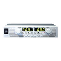
Nemic-Lambda TDK-Lambda Genesys GENH600-1.3 Manual (74 pages)
Programmable Regulated Power Supplies
Brand:
Nemic-Lambda
| Category:
Power Supply
| Size: 2.83 MB
Table of Contents
Table of Contents
3
Chapter 1 General Information
12
Introduction
12
General Description
12
Features and Options
12
Multiple Output Power System
13
Control Via the Serial Communication Port
13
Analog Voltage Programming and Monitoring
13
Parallel Operation
13
Output Connections
13
Cooling and Mechanical Construction
14
Accessories
14
General
14
Serial Link Cable
14
Misc. Hardware
14
AC Cables
14
Serial Port Cables
14
Chapter 2 Specifications
15
Output Rating
15
Input Characteristics
15
Constant Voltage Mode
15
Constant Current Mode
15
Analog Programming and Monitoring
15
Programming and Readback
16
Protective Functions
16
Front Panel
16
Environmental Conditions
16
Mechanical
16
Safety/Emc
16
Supplemental Characteristics
17
Outline Drawings
18
Chapter 3 Installation
19
General
19
Preparation for Use
19
Initial Inspection
19
Rack Mounting
19
To Install the Power Supply in a Rack
19
Rack Mount Slides
20
Location Mounting and Cooling
20
Ac Source Requirements
20
Ac Input Power Connection
20
AC Input Connector, 1500W Models
21
AC Input Connector, 750W Models
21
AC Input Cord
21
AC Input Wire Connection, 1500W Models
21
Turn-On Checkout Procedure
22
General
22
Prior to Operation
22
Constant Voltage Check
23
Constant Current Check
23
OVP Check
23
UVL Check
23
Foldback Check
24
Address Setting
24
Baud Rate Setting
24
Connecting the Load
24
Load Wiring
24
Current Carrying Capacity
24
Wire Termination
25
Noise and Impedance Effects
26
Inductive Loads
26
Making the Load Connections
26
Connecting Single Loads, Local Sensing (Default)
29
Connecting Single Loads, Remote Sensing
29
Connecting Multiple Loads, Radial Distribution Method
29
Multiple Loads Connection with Distribution Terminals
30
Grounding Outputs
30
Local and Remote Sensing
31
Local Sensing
31
Remote Sensing
32
J2 Sense Connector Technical Information
32
Repackaging for Shipment
32
Chapter 4 Front and Rear Panel Controls and Connectors
33
Introduction
33
Front Panel Controls and Indicators
33
Rear Panel
35
Rear Panel Sw1 Setup Switch
36
SW1 Positions Functions
37
Resetting the Switch
37
Rear Panel J1 Programming and Monitoring Connector
38
Making J1 Connections
38
Chapter 5 Local Operation
40
Introduction
40
Standard Operation
40
Constant Voltage Mode
40
Constant Current Operation
40
Automatic Crossover
41
Over Voltage Protection (Ovp)
41
Setting the OVP Level
41
Activated OVP Protection Indications
41
Resetting the OVP Circuit
41
Under Voltage Limit (Uvl)
42
Setting the UVL Level
42
Foldback Protection
42
Setting the Foldback Protection
42
Resetting Activated Foldback Protection
42
Output On/Off Control
42
Output Shut-Off (So) Control Via Rear Panel J1 Connector
42
Enable/Disable Control Via Rear Panel J1 Connector
43
CV/CC Signal
43
Ps_Ok Signal
43
Safe Start and Auto-Restart Modes
44
Automatic Start Mode
44
Safe Start Mode
44
Over Temperature Protection (Otp)
44
Last Setting Memory
44
Series Operation
44
Series Connection for Increased Output Voltage
45
Series Connection for Positive and Negative Output Voltage
46
Parallel Operation
47
Basic Parallel Operation
47
Advanced Parallel Operation
47
Daisy-Chain Connection
49
Front Panel Locking
49
Unlocked Front Panel
49
Locked Front Panel
49
Chapter 6 Remote Analog Programming
50
Introduction
50
Local/Remote Analog Controll
50
Local/Remote Analog Indication
50
Remote Voltage Programming of Output Voltage and Current Limit
51
Resistive Programming of Output Voltage and Current Limit
52
Remote Monitoring of Output Voltage and Current
53
Chapter 7 Rs232 & Rs485 Remote Control
54
Introduction
54
Configuration
54
Default Setting
54
Address Setting
54
RS232 or RS485 Selection
54
Baud Rate Setting
54
Setting the Unit into Remote or Local Mode
54
RS232/458 Port at Local Mode
55
Front Panel in Remote Mode
55
Rear Panel Rs232/485 Connector
55
Connecting Power Supplies to Rs232 or Rs485 Bus
56
Single Power Supply
56
Multi Power Supplies Connection to RS232 or RS485 Bus
57
Communication Interface Protocol
57
Data Format
57
Addressing
57
End of Message
57
Command Repeat
57
Checksum
57
Acknowledge
57
Error Message
58
Backspace
58
Error Messages
58
Command Set Description
58
General Guides
58
Command Set Categories
58
Initialization Control Commands
59
ID Control Commands
59
Output Control Commands
59
Global Output Commands
61
Status Control Commands
62
Status, Error and Srq Registers
63
General
63
Conditional Registers
63
Service Request: Enabled and Event Registers
64
Serial Communication Test Set-Up
67
Chapter 8 Isolated Analog Programming Option
68
Introduction
68
Specifications
68
Isolated Programming & Monitoring Connector
69
Setup and Operating Instructions
70
Setting up the Power Supply for 0-5/0-10V Isolated Programming and Monitoring
70
Setting up the Power Supply for 4-20Ma Isolated Programming and Monitoring
70
Advertisement
Advertisement
Related Products
Nemic-Lambda TDK-Lambda Genesys GENH6-100
Nemic-Lambda TDK-Lambda Genesys GENH60-12.5
Nemic-Lambda TDK-Lambda Genesys GENH8-90
Nemic-Lambda TDK-Lambda Genesys GENH12.5-60
Nemic-Lambda TDK-Lambda Genesys GENH20-38
Nemic-Lambda TDK-Lambda Genesys GENH30-25
Nemic-Lambda TDK-Lambda Genesys GENH40-19
Nemic-Lambda TDK-Lambda Genesys GENH100-7.5
Nemic-Lambda TDK-Lambda Genesys GENH150-5
Nemic-Lambda TDK-Lambda Genesys GENH300-2.5
Nemic-Lambda Categories
Power Supply
More Nemic-Lambda Manuals
Login
Sign In
OR
Sign in with Facebook
Sign in with Google
Upload manual
Upload from disk
Upload from URL