Sign In
Upload
Manuals
Brands
National Instruments Manuals
Adapter
SC-2052
National Instruments SC-2052 Manuals
Manuals and User Guides for National Instruments SC-2052. We have
2
National Instruments SC-2052 manuals available for free PDF download: User Manual
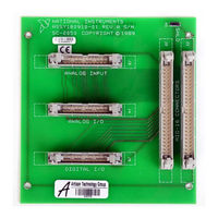
National Instruments SC-2052 User Manual (92 pages)
General-Purpose Termination Breadboards
Brand:
National Instruments
| Category:
Computer Hardware
| Size: 2 MB
Table of Contents
Table of Contents
6
About this Manual
11
Organization of this Manual
11
Conventions Used in this Manual
12
Related Documentation
12
Customer Communication
13
Chapter 1 Introduction
14
About the SC-207X Series Boards
14
Table 1-1. DAQ Devices for Use with SC-207X Series Boards
15
What You Need to Get Started
17
Optional Equipment
17
Software
17
Unpacking
18
Chapter 2 SC-2070 Board
19
Analog Input
20
Figure 2-1. SC-2070 Board Parts Locator Diagram
20
Temperature Sensor
21
Figure 2-2 Onboard Equivalent Circuit
21
Table 2-1. Component Positions in each Channel
21
Shield Ground
22
Fuse and Power LED
22
Digital and Timing Signals
22
Figure 2-3. W1 Jumper Settings
22
Figure 2-4. W2 Jumper Settings
22
Board-To-Board Cabling
23
Figure 2-5. Direct Connection between an MIO-16 Board and the SC-2070 Board
23
Figure 2-6. Connection between an MIO-16 Board and the SC-2070 Board Via the SC-2050 Board
23
Table 2-2. DAQ Boards Used with the SC-2070 Board
23
Mounting
24
Applications
24
Soldering and Desoldering on the SC-2070 Board
24
Channel Configurations
25
Connecting Nonreferenced or Floating Signal Sources
25
Differential Inputs
25
Single-Ended Inputs
26
Connecting Ground-Referenced Signal Sources
27
Differential Inputs
27
Single-Ended Inputs
27
Building Lowpass Filters
28
Figure 2-8. Normalized Frequency Response of Lowpass Filter
28
Building Highpass Filters
30
Figure 2-10. Normalized Frequency Response of Highpass Filter
30
Building Attenuators (Voltage Dividers)
32
Figure 2-12. Attenuator for Use with Differential Inputs
33
Working with Thermocouples
34
Using the SC-2070 Board for Thermocouple Measurements
35
Input Filtering and Broken Thermocouple Detection (Optional)
35
Selecting the Gain and Input Ranges
36
Figure 2-13. Thermocouple Circuit with Open Thermocouple Detect and Lowpass Noise Filter
36
Linearizing the Data
37
Table 2-3. Thermocouple Voltage Output Extremes (MV)
37
Table 2-4. NBS Polynomial Coefficients
38
Differential Measurements
39
An Example of Using Thermocouples in Differential Mode
39
Single-Ended Measurements
40
An Example of Using Thermocouples in Single-Ended Mode
40
Sources of Error
41
Thermocouple Measurement Accuracies
41
Additional Signal Connection Information
42
Table 2-5. Thermocouple Measurement Accuracies
42
Chapter 3 SC-2071 Board
43
Analog Input
44
Figure 3-1. SC-2071 Board Parts Locator Diagram
44
Figure 3-2. Onboard Equivalent Circuit
45
Table 3-1. Component Positions in each Channel
45
Temperature Sensor
46
Shield Ground
46
Fuse and Power LED
46
Figure 3-3. W1 Jumper Settings
46
Figure 3-4. W2 Jumper Settings
46
Digital and Timing Signals
47
Board-To-Board Cabling
47
Figure 3-5. Direct Connection between a Lab/1200 Device and the SC-2071 Board
47
Table 3-2. DAQ Devices Used with the SC-2071 Board
47
Figure 3-6. Daisy-Chaining a Lab/1200 Device to a BNC-2081
48
Figure 3-7. Connection between a Lab/1200 Device and the SC-2071 Board Via the SC-2053 Board
48
Mounting
49
Applications
49
Soldering and Desoldering on the SC-2071 Board
49
Connecting Floating Signal Sources
50
Connecting Grounded Signal Sources
50
Building Lowpass Filters
50
Figure 3-8. Normalized Frequency Response of Lowpass Filter
51
Building Highpass Filters
52
Figure 3-10. Normalized Frequency Response of Highpass Filter
53
Building Attenuators (Voltage Dividers)
54
Figure 3-12. Attenuator for Use with SC-2071 Board Inputs
55
Working with Thermocouples
56
Using the SC-2071 Board for Thermocouple Measurements
57
Input Filtering and Broken Thermocouple Detection (Optional)
57
Selecting the Gain and Input Ranges
58
Figure 3-13. Thermocouple Circuit with Open Thermocouple Detect and Lowpass Noise Filter
58
Linearizing the Data
59
Table 3-3. Thermocouple Voltage Output Extremes (MV)
59
Measurement Connections
60
Table 3-4. NBS Polynomial Coefficients
60
An Example of Using Thermocouples
61
Sources of Error
61
Thermocouple Measurement Accuracies
62
Additional Signal Connection Information
63
Table 3-5. Thermocouple Measurement Accuracies
63
Chapter 4 SC-2072 Board
64
Figure 4-1. SC-2072 Board Parts Locator Diagram
65
Signal Connections
66
Figure 4-2. SC-2072D Board Parts Locator Diagram
66
Power Connections
67
Table 4-1. Switch S2 Settings for National Instruments DAQ Devices
67
Fuses and Power LED
68
Board-To-Board Cabling
69
Figure 4-3. Direct Connection between a TIO-10 Board and the SC-2072 Board
69
Figure 4-4. Connection between a DIO-24 Board and the SC-2072 Board Via the SC-2051 Board
69
Mounting
70
Soldering and Desoldering on the SC-2072 Board
70
Installation and Connections
71
Hardware Installation
71
Hardware Installation for the SC-2070 and the SC-2071
71
Hardware Installation for the SC-2072
72
Installing the SC-205X Series Cable Adapter Boards
72
Installing the BNC-2081 Analog Breakout Board
73
Rack Mounting
73
Figure 5-1. Mounting Locations for SC-207X Series Boards
73
Figure 5-2. Attaching a Mountable Board to the Chassis
73
Figure 5-3. Double-Height Mounting
74
External Power Connection (if Necessary)
75
Table 5-1. Amount of Power Supplied by DAQ Devices
76
SC-207X Series Board Connection
77
Figure 5-4. Connections between DAQ Devices and SC-205X Series Boards and between SC-205X Series Boards and SC-2070 and SC-2071 Boards
77
Signal Connections
78
Ribbon Cable Connectors
78
Screw Terminal Connections for the SC-2070 and the SC-2071
78
Table 5-2. SC-205X Series Board Connectors Compatible with the SC-207X Series Boards
78
Screw Terminal Connections for the SC-2072
79
Rack-Mount Chassis Cover Attachment
79
Appendix A Specifications
80
Customer Communication
82
Glossary
85
Index
86
Advertisement
National Instruments SC-2052 User Manual (119 pages)
Brand:
National Instruments
| Category:
Adapter
| Size: 2 MB
Table of Contents
Table of Contents
5
About this Manual
11
Organization of this Manual
11
Conventions Used in this Manual
12
National Instruments Documentation
13
Customer Communication
14
Related Documentation
14
About the SC-205X Series
15
Introduction
15
Table 1-1. DAQ Hardware Used with the SC-205X Series Adapters
16
What You Need to Get Started
17
Optional Equipment
18
Software Programming Choices
18
Unpacking
18
Figure 2-1. SC-2050 Parts Locator Diagram
20
Connectors
21
SC-2050 Connection
21
Figure 2-2. SC-2050 Connections
22
Table 2-1. SC-2050 Connectors
22
Figure 2-3. Pin Assignments for SC-2050 I/O Connectors J1 and J2
23
Figure 2-4. Pin Assignments for SC-2050 Analog Input Connector J3
24
Figure 2-5. Pin Assignments for SC-2050 Analog I/O Connector J4
24
Cabling
25
Figure 2-6. Pin Assignments for SC-2050 Digital I/O Connector J5
25
Mounting
25
Figure 3-1. SC-2051 Parts Locator Diagram
27
Connectors
28
SC-2051 Connection
28
Figure 3-2. SC-2051 Connections
29
Table 3-1. SC-2051 Connectors
29
Figure 3-3. Pin Assignments for SC-2051 I/O Connectors J1 and J2
30
Figure 3-4. Pin Assignments for SC-2051 I/O Connector J3
31
Figure 3-5. Pin Assignments for SC-2051 I/O Connector J4
31
Cabling
32
Figure 3-6. Pin Assignments for SC-2051 I/O Connector J5
32
Mounting
32
Figure 4-1. SC-2052 Parts Locator Diagram
34
Connectors
35
SC-2052 Connection
35
Figure 4-2. SC-2052 Connections
36
Table 4-1. SC-2052 Connectors
36
Figure 4-3. Pin Assignments for SC-2052 I/O Connectors J1 and J2
37
Mounting
39
Cabling
40
Connectors
43
SC-2053 Connection
43
Table 5-1. SC-2053 Connectors
44
Mounting
47
Cabling
48
SC-2054 Connection
50
Connectors
51
Table 6-1. SC-2054 Connectors
52
Cabling
57
Mounting
57
Connectors
59
SC-2055 Connection
59
Table 7-1. SC-2055 Connectors
60
Mounting
63
Cabling
64
SC-2056 Connection
66
Connectors
67
Table 8-1. SC-2056 Connectors
69
Mounting
80
Cabling
81
SC-2057 Connection
83
Connectors
84
Or 8-Channel SSR Backplane
87
Mounting
93
Cabling
94
SCXI-1348 Cable Adapter Installation
94
Hardware Installation
97
Installation and Operation
97
Rack Mounting
97
Shield Selection
99
Cable Connections
102
Rack-Mount Chassis Cover Attachment
102
Signal Conditioning Accessory Installation
102
Appendix A Specifications
104
Customer Communication
105
Glossary
110
Index
115
Advertisement
Related Products
National Instruments SC-205X Series
National Instruments SC-2050
National Instruments SC-2051
National Instruments SC-2053
National Instruments SC-2054
National Instruments SC-2055
National Instruments SC-2056
National Instruments SC-2057
National Instruments SC-2072
National Instruments SC-2042-RTD
National Instruments Categories
Control Unit
I/O Systems
Controller
Computer Hardware
Measuring Instruments
More National Instruments Manuals
Login
Sign In
OR
Sign in with Facebook
Sign in with Google
Upload manual
Upload from disk
Upload from URL