Sign In
Upload
Manuals
Brands
National Instruments Manuals
Computer Hardware
GPIB-1014 Series
National Instruments GPIB-1014 Series Manuals
Manuals and User Guides for National Instruments GPIB-1014 Series. We have
2
National Instruments GPIB-1014 Series manuals available for free PDF download: User Manual, Getting Started
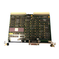
National Instruments GPIB-1014 Series User Manual (254 pages)
Brand:
National Instruments
| Category:
Computer Hardware
| Size: 1 MB
Table of Contents
Table of Contents
6
About this Manual
12
Organization of this Manual
12
Conventions Used in this Manual
13
Related Documentation
13
Customer Communication
14
Chapter 1 Introduction
15
Figure 1-1. GPIB-1014 Interface Board
16
What Your Kit Should Contain
17
Optional Equipment
17
Unpacking
18
General Description
20
Vmebus Characteristics
20
Vmebus Slave-Addressing
20
Vmebus Slave-Data
21
Table 2-3. 68450 Internal DMA Registers
22
Vmebus Master-Direct Memory Access
23
Table 2-4. GPIB-1014 Configuration Registers
23
Interrupter
24
Data Transfer Bus (DTB) Requester
25
Vmebus Modules Not Provided
25
Diagnostic Aids
25
Data Transfer Features
25
Programmed I/O Transfers
26
GPIB-1014 Functional Description
26
Figure 2-1. GPIB-1014 with a Vmebus Computer
27
Figure 2-2. GPIB-1014 in a Multiprocessor Application
28
Figure 2-3. GPIB-1014 Block Diagram
29
Table 2-5. GPIB-1014 IEEE 488 Interface Capabilities
31
Table 2-6. GPIB-1014 IEEE 1014 Interrupter Compliance Levels
33
Configuration and Installation
34
Configuration
34
Figure 3-1. Parts Locator Diagram
35
Access Mode
36
Base Address
36
Figure 3-2. Access Mode after RESET
36
Set Base Address Using Jumper Block W1
37
Set Base Address Using Compare Address Lines
37
Figure 3-3. Configuration for GPIB-1014 Base Address 2000 (Hex)
37
DMA Address Modifier Code Output
38
Figure 3-4. Default Settings of am Code Jumpers W3, W4, and W5
38
Table 3-1. Programming Values for Default Settings of W3, W4, and W5
39
Table 3-2. Setting the Address Modifier Code Bits (AM5-AM0)
39
Other Configuration Parameters
40
Installation
40
Verification of System Compatibility
40
Table 3-3. GPIB-1014 Pin Assignment on Vmebus Connector P1
41
Table 3-4. GPIB-1014 Pin Assignment on Vmebus Connector P2
42
Cabling
43
Verification Testing
43
Table 4-1. GPIB-1014 Register Map
44
Register Bit Descriptions
45
Register Sizes
45
Register Description
45
Register Description Format
46
Interface Registers
47
Figure 4-1. Interface Registers
48
Figure 4-2. Writing to the Hidden Registers
49
Data in Register (DIR)
50
Command/Data out Register (CDOR)
51
Interrupt Status Register 1 (ISR1)
52
Interrupt Mask Register 1 (IMR1)
52
Interrupt Status Register 2 (ISR2)
58
Interrupt Mask Register 2 (IMR2)
58
Serial Poll Status Register (SPSR)
63
Serial Poll Mode Register (SPMR)
63
Address Status Register (ADSR)
64
Address Mode Register (ADMR)
66
Command Pass through Register (CPTR)
69
Auxiliary Mode Register (AUXMR)
71
Table 4-4. Auxiliary Command Summary
72
Table 4-5. Auxiliary Commands: Detail Description
73
Hidden Registers
77
Internal Counter Register (ICR)
78
Parallel Poll Register (PPR)
79
Table 4-6. Examples for Configuring the PPR
80
Auxiliary Register a (AUXRA)
81
Auxiliary Register B (AUXRB)
83
Auxiliary Register E (AUXRE)
85
Address Register 0 (ADR0)
86
Address Register (ADR)
87
Address Register 1 (ADR1)
88
End of String Register (EOSR)
89
DMA Registers
90
Table 4-7. DMAC DMA Channel Register Set
90
Figure 4-3. DMA Register Memory Map
91
Address Registers
92
Transfer Count Registers
93
Function Code Registers
94
Device Control Register
95
Operation Control Register
97
Sequence Control Register
99
Channel Control Register
100
Channel Status Register
102
Channel Error Register
104
Channel Priority Register
105
Interrupt Vector Registers
106
General Control Register
107
Configuration Registers
108
Configuration Register 1 (CFG1)
108
Configuration Register 2 (CFG2)
110
Programming Considerations
112
Initialization
112
The GPIB-1014 as GPIB Controller
114
Becoming Controller-In-Charge (CIC) and Active Controller
114
Sending Remote Multiline Messages (Commands)
115
Going from Active to Standby Controller
115
Going from Standby to Active Controller
115
Going from Active to Idle Controller
116
The GPIB-1014 as GPIB Talker and Listener
117
Programmed Implementation of Talker and Listener
117
Addressed Implementation of the Talker and Listener
117
Address Mode 1
117
Address Mode 2
118
Address Mode 3
118
Sending/Receiving Messages
119
Using Direct Memory Access
119
DMA Transfers Without the Carry Cycle
121
Figure 5-1. DMA Transfer Without Carry Cycle
121
DMA Transfers with the Carry Cycle
124
Figure 5-2. DMA Transfer with Carry Cycle
124
Polling During Dmas
128
Sending END or EOS
128
Terminating the Transfer and Checking the Result
128
Terminating on END or EOS
130
Using Programmed I/O
131
Sending and Receiving Data
131
Sending END or EOS
131
Terminating on END or EOS
131
Interrupts
132
Serial Polls
134
Conducting a Serial Poll
134
Responding to a Serial Poll
134
Parallel Polls
134
Conducting a Parallel Poll
135
Responding to a Parallel Poll
136
Chapter 6 Theory of Operation
137
Vmebus Interface
137
Data Lines
137
Slave Read and Write Transfers
137
DMA Transfers
137
Control Signals
138
Address
138
Control Equations of Transceivers
139
Table 6-1. Control Equations of Transceivers
139
Clock and Reset Circuitry
140
Configuration Registers
141
Configuration Register 1
141
Configuration Register 2
143
Timing State Machine
143
Slave Cycles
143
DMA Cycles
144
DMA Gating and Control
145
Interrupter
146
DTB Requester and Controller
146
Figure 6-1. DTB Requester and Controller Flip-Flop Operations
147
GPIB Synchronization and Interrupt Control
149
68450 Dmac
152
DMAC Channel Operation
152
Initialization and Transfer Phases
152
Device (TLC)/DMAC Communication
153
DMA Requests
154
Data Transfers
154
Operands and Addressing
155
Address Register Operation
155
Transfer Count Register Operation
156
Initiation and Control of Channel Operation
156
Initiating the Operation
156
The Continue Mode of Operation
156
Halt
156
Software Abort
157
Interrupt Enable
157
Block Termination
157
Multiple Block Operations
157
Continued Operations
157
Array Chaining Operations
158
Linked Chaining Operations
159
Figure 6-2. Array Format for Array Chaining Modes
159
Error Conditions
160
GPIB Interface
162
Test and Troubleshooting
163
DMA Stand-Alone Testing
163
GPIB Interface Testing
163
Diagnostic and Troubleshooting Test Procedures
165
Interpreting Test Procedures
165
GPIB-1014 Hardware Installation Tests
166
Hardware Specifications
174
Table A-1. Electrical Characteristics
174
Table A-2. Environmental Characteristics
174
Parts List and Schematic Diagrams
176
Appendix C Sample Programs
185
Multiline Interface Messages
206
Appendix E Operation of the GPIB
209
Types of Messages
209
Talkers, Listeners, and Controllers
209
The Controller-In-Charge and System Controller
210
GPIB Signals and Lines
210
Data Lines
210
Handshake Lines
210
DAV (Data Valid
211
Interface Management Lines
211
ATN (Attention
211
IFC (Interface Clear
211
REN (Remote Enable
211
SRQ (Service Request
211
EOI (End or Identify
211
Physical and Electrical Characteristics
212
Configuration Requirements
214
Related Documents
215
Appendix F Mnemonics Key
216
Customer Communication
227
Glossary
232
Index
254
Advertisement
National Instruments GPIB-1014 Series Getting Started (30 pages)
Interface boards and the NI-488M multitasking software for Motorola UNIX
Brand:
National Instruments
| Category:
Computer Hardware
| Size: 0 MB
Table of Contents
Table of Contents
11
Chapter 1 Introduction
12
What Your Kit Should Contain
12
Optional Equipment
13
Software Description
13
Chapter 2 Installation and Configuration
14
Step 1. Prepare for Software Installation
14
Step 2. Install the Software
14
Set up a Working Directory
14
Install the Utility Files
15
Install the C Library
15
Install the NI-488M Driver
16
Step 3. Configure and Install the Hardware
18
Unpack Your GPIB-1014
18
Configure the GPIB-1014 Series Board
18
Configure the GPIB-1014 or GPIB-1014D
19
Configure the GPIB-1014P or GPIB-1014DP
19
Install the GPIB-1014 Series Board
19
Step 4. Verify the Software Installation
20
Step 5. Configure the Software
21
Ibconf Example
21
Exiting Ibconf
22
Appendix A Troubleshooting
23
Appendix B Customer Communication
24
Advertisement
Related Products
National Instruments GPIB-PC
National Instruments GPIB-PCII
National Instruments GPIB-PCIIA
National Instruments GPIB-PCIIB
National Instruments GPIB-LPT
National Instruments GPIB-1014D
National Instruments GPIB-1014DP
National Instruments GPIB-1014P
National Instruments GPIB-ENET-1000
National Instruments GPIB-100A
National Instruments Categories
Control Unit
I/O Systems
Controller
Computer Hardware
Measuring Instruments
More National Instruments Manuals
Login
Sign In
OR
Sign in with Facebook
Sign in with Google
Upload manual
Upload from disk
Upload from URL