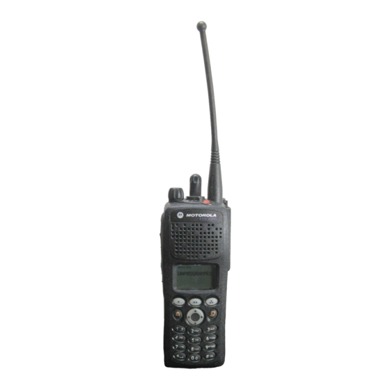
Motorola ASTRO XTS 2500I Model 1 Manuals
Manuals and User Guides for Motorola ASTRO XTS 2500I Model 1. We have 8 Motorola ASTRO XTS 2500I Model 1 manuals available for free PDF download: Service Manual, User Manual
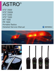
Motorola ASTRO XTS 2500I Model 1 Service Manual (817 pages)
Brand: Motorola
|
Category: Portable Radio
|
Size: 44 MB
Table of Contents
Advertisement
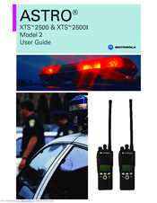
Motorola ASTRO XTS 2500I Model 1 User Manual (138 pages)
Model II
Brand: Motorola
|
Category: Portable Radio
|
Size: 10 MB
Table of Contents

Motorola ASTRO XTS 2500I Model 1 User Manual (138 pages)
Brand: Motorola
|
Category: Portable Radio
|
Size: 10 MB
Table of Contents
Advertisement
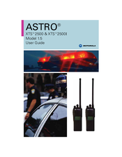
Motorola ASTRO XTS 2500I Model 1 User Manual (82 pages)
Brand: Motorola
|
Category: Two-Way Radio
|
Size: 1 MB
Table of Contents

Motorola ASTRO XTS 2500I Model 1 User Manual (82 pages)
Brand: Motorola
|
Category: Portable Radio
|
Size: 1 MB
Table of Contents

Motorola ASTRO XTS 2500I Model 1 User Manual (82 pages)
Digital Portable Radio
Brand: Motorola
|
Category: Portable Radio
|
Size: 9 MB
Table of Contents

Motorola ASTRO XTS 2500I Model 1 User Manual (156 pages)
Motorola ASTRO XTS 2500; ASTRO XTS 2500I Digital Portable radio
Brand: Motorola
|
Category: Portable Radio
|
Size: 2 MB

Motorola ASTRO XTS 2500I Model 1 User Manual (138 pages)
Brand: Motorola
|
Category: Two-Way Radio
|
Size: 1 MB