Sign In
Upload
Manuals
Brands
Motor Power Company Manuals
Servo Drives
DUET_FL 48/10
Motor Power Company DUET_FL 48/10 Drives Manuals
Manuals and User Guides for Motor Power Company DUET_FL 48/10 Drives. We have
1
Motor Power Company DUET_FL 48/10 Drives manual available for free PDF download: User Manual
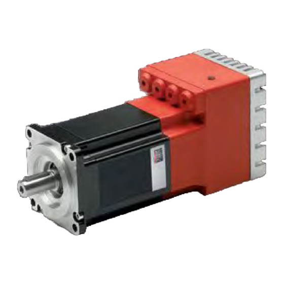
Motor Power Company DUET_FL 48/10 User Manual (196 pages)
Brand:
Motor Power Company
| Category:
Servo Drives
| Size: 2 MB
Table of Contents
Table of Contents
8
Documentation
22
Supply State and Scope of Supply
22
2Safety Notes for Electrical Drives and Controllers
24
General Notes
24
2.1 Danger Resulting from Misuse
25
Safety Notes
26
General Safety Notes
26
Safety Notes for Assembly and Maintenance
27
Protection against Contact with Electrical Parts
28
1Protection against Electrical Shock by Means of Protective Extra-Low Voltage (PELV)
29
Protection against Dangerous Movements
29
Protection against Contact with Hot Parts
30
2Protection During Handling and Assembly
30
Preparation for Commissioning
32
System Overview
32
Connecting the DUET_FL to the Control System
32
Installation and Start of the DUET_FL Servocommandertm
32
Initial Parameterization of the Controller
33
Commissioning
33
Parameter Set in the Delivery State
33
Manual Commissioning
33
Parameterization Using the Motor Database
34
Basic Parameterization of New Motors
35
Angle Encoders
35
1Motor Data
38
Power Stage
40
2Current Controller
41
DC Bus Monitoring
42
Motor Temperature Monitoring
43
Configuring Application Parameters
44
General Configuration
44
Configuring the Display Units
44
3.2 Defining Input Limits
46
3.3 Selecting Safety Parameters
47
Configuring the Controller Enable Logic
48
Configuring the Limit Switch Polarity
49
Setting the Direction of Rotation
50
Making the System Ready for Operation, Enabling the Power Stage
50
Current and Speed Control
52
Function Overview
52
Speed-Controlled Mode
54
1Optimizing the Speed Controller
54
Torque-Controlled Mode
57
4.2 Setpoint Assignment through Setpoint Selectors
57
Speed-Controlled Mode
58
Torque-Controlled Mode
58
1Setpoint Assignment through RS232
59
Setpoint Ramp
59
Torque Limitation
60
5Positioning Mode
61
5.1 Function Overview
61
Activating the Operating Mode
62
5.2 Configuring and Optimizing the Position Controller
63
Position Controller Optimization
64
Global Positioning Settings
65
Parametrizing Position Sets
66
Setting of Digital Outputs
70
Homing
70
Parameterizing the Homing Run
74
Course Program
77
Creating a Course Program
79
Course Program Options
80
End of Program
81
Position Branch
81
Branch (Line)
83
Debugging a Course Program
85
Function of the Inputs and Outputs
86
5.3 Digital Inputs DIN0 to DIN9
86
Configuring the Digital Inputs
88
Extended Function of the Digital Inputs (Tipp & Teach)
88
8.2.1 Teaching Positions
89
5.5 Digital Outputs DOUT0 to DOUT3
91
Configuring the Digital Outputs
91
Configuring the Messages for the Digital Outputs
92
Incremental Encoder Emulation through DOUT1 and DOUT2
93
Holding Brake DOUT3
95
Brake Functions
95
Analog Inputs AIN0 and AIN1
96
Analog Output AMON
98
Communication Interfaces
99
Control through the CAN Bus
99
Function Overview
99
1Processing of CAN Messages
100
2Configuring the Canopen Communication Parameters
100
Control through the Serial Interface
101
Function Overview
101
3Serial Communication through DUET_FL Servocommandertm
102
Configuring the RS232 Communication Parameters
102
Transfer Window
103
Communication Window for RS232 Transmission
103
Control through the Technology Interface
104
Error Messages/Error Table
105
Error Monitoring in the DUET_FL
105
4Overcurrent and Short-Circuit Monitoring
105
DC Bus Voltage Monitoring
105
Logic Supply Monitoring
106
Heat Sink Temperature Monitoring
106
Motor Monitoring
106
Motion Sequence Monitoring
107
Additional Internal Monitoring Functions
107
Operating Hour Meter
107
Error Overview
107
Error Display in DUET_FL Servocommandertm
112
6.2 Error Management
113
Appendix
114
DUET_FL Servocommandertm Operating Instructions
114
Standard Buttons
114
Numerical Input Fields
114
Control Elements
115
Display of Setpoints and Actual Values
115
2Standard Window
116
Directories
117
3Communication Via Communication Objects
117
Quitting the Program
118
Setting up the Serial Communication
119
Fast Access Via the Tool Bar
122
Using the Oscilloscope Function
123
Oscilloscope Settings
123
Oscilloscope Window
125
6.3 Serial Communication Protocol
128
List of Communication Objects
130
Basic Units
138
11.7.2 Bit Configuration for Command Word / Status Word / Error Word
139
Extended Options in the "Display Units" Menu
143
Configuration of User-Defined Display Units
143
Decimal Places
144
Direct Input of Distance, Speed and Acceleration Units
144
Course Program: Examples
145
1Example 1: Linear Linking of Positions
145
Example 2: Linear Linking of Positions and Setting of a Digital Output
146
Example 3: Setting and Inquiring Digital Inputs and Outputs; Infinite Loops
147
Timing Diagrams
147
1Switch-On Sequence
148
Positioning / Destination Reached
149
Speed Signal
149
Quit Error150
150
Limit Switch
150
Parameter Set Management
151
General
151
Loading and Saving Parameter Sets
152
Loading Firmware into the DUET_FL / Firmware Update
156
1Loading the Firmware
156
Technical Data
159
Ambient Conditions and Qualification
159
2Dimensions and Weight
159
3Performance Data
159
Motor Temperature Monitoring
161
4Motor Connection Data [X301 - X303]
161
5Resolver [X2]
161
6Analog Hall Encoder Evaluation [X2]
162
Hiperface Encoder Evaluation [X2]
162
7Incremental Encoder Evaluation [X2] - Only DUET_FL 48/10 FB
162
Six-Step Hall Sensor and Block Commutation [X2]
163
8Rs232 [X1]
163
9CAN-Bus [X1]
163
10Analog Inputs and Outputs [X1]
163
11Digital Inputs and Outputs [X1]
164
12Incremental Encoder Output [X1]
164
11.14. Mechanical Installation
165
Important Notes
165
Position and Connection of the Pin-And-Socket Connectors
166
Housing Dimensions
167
Installation
168
Connectors at the DUET_FL 48/10
169
Connection: Power Supply and I/O [X1]
169
1Connection: Angle Encoder [X2]
170
Connection: Motor [X301 - X303]
171
2Connection: Holding Brake [X3]
171
Connection: Extension Port [X8]
172
Connectors at the DUET_FL 48/10 IC
173
Connection: Power Supply and I/O [X1]
173
3Connection: Motor, Encoder, Brake, Extensions
174
Connectors at the DUET_FL 48/10 FB
174
Connection: Power Supply and I/O [X1]
174
Connection: Motor, Encoder, Brake, Extensions
175
Brake Resistance Connection [X304 - X305]
176
Connection: CAN Bus [X401] and [X402]
177
Connection: Serial Parameterization Interface [X5]
178
Connection: Extension Port [X8]
179
Electrical Installation of the DUET_FL 48/10
181
Connection to Power Supply and Control in System
181
EMERGENCY off / EMERGENCY STOP - Terminology and Standards
183
EMERGENCY off / EMERGENCY STOP Wiring Examples
185
Notes Concerning Safe and EMC-Compliant Installation
188
Definitions and Terminology
188
General Information Concerning EMC
188
1EMC Ranges: First and Second Environment
188
Connection between the DUET_FL and the Motor
189
2Connection between the DUET_FL and the Power Supply Unit
189
Advertisement
Advertisement
Related Products
Motor Power Company TETRA COMPACT 4 Series
Motor Power Company DMR 50
Motor Power Company DMR 50-5
Motor Power Company DMR 50-5/50 V3.0
Motor Power Company Duet AD 80
Motor Power Company DUET AD Series
Motor Power Company FLEXI PR0-1D5
Motor Power Company FLEXI PRO Series
Motor Power Company FLEXI PRO-003
Motor Power Company FLEXI PRO-006
Motor Power Company Categories
Servo Drives
Engine
DC Drives
More Motor Power Company Manuals
Login
Sign In
OR
Sign in with Facebook
Sign in with Google
Upload manual
Upload from disk
Upload from URL