Sign In
Upload
Manuals
Brands
Moseley Manuals
Transmitter
Starlink SL9003Q
Moseley Starlink SL9003Q Manuals
Manuals and User Guides for Moseley Starlink SL9003Q. We have
2
Moseley Starlink SL9003Q manuals available for free PDF download: User Manual
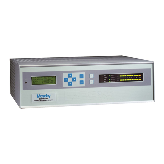
Moseley Starlink SL9003Q User Manual (136 pages)
Digital Studio Transmitter Link
Brand:
Moseley
| Category:
Transmitter
| Size: 8 MB
Table of Contents
Able of Contents
4
Table of Contents
4
System Features and Specificati Ns
11
Section 1 Ystem Features and Pecifications
12
Specifications
12
System Specifications
12
System Features
13
Receiver Specifications
16
Transmitter Specifications
16
Audio Encoder Specifications
17
Audio Decoder Specifications
17
System Introduction
13
Regulatory Notices
18
Intelligent Multiplexer Specifications
18
Section 2 Quick Tart
20
Audio
20
External Communications Equipment
20
Identifying Audio Connections (4-Channel)
20
Identifying Data Channels on the M X Module
20
RF Parameters
20
Performance
20
Transmitter Performance Check
20
Receiver Performance Check
20
Npacking
21
Notices
21
Rack Mount
22
Transmitter Power- P Setting
23
Typical Installations
23
Default Settings and Parameters
28
Data Channel
29
QAM Modulator/Demodulator
29
Details, Details, Details
31
Section 3 Installation
32
AC Line Voltage
33
Power Requirements
33
Power Supply Card Slot Details
33
Rear Panel Connections
33
DC Input Option
34
Fusing
34
Preliminary Bench Tests
35
RF Bench Test
36
Audio and Data Channel Bench Test
38
Site Installation
39
Facility Requirements
41
Power Requirements
41
Rack Mount Installation
41
Antenna Mounting
43
Antenna/Feed System
43
Environmental Seals
43
Transmission Line
43
Link Alignment
45
Section 4 Operation
46
Front Panel Operation
47
Introduction
47
LCD Screen Display
47
Cursor and Screen Control Buttons
48
Status Indicators
49
Launch Screens
58
Main Menu Screen
58
Meter
61
System: Card View
61
System: Info
62
System: Power Supply
62
System: Basic Card Setup
63
System: Date/Time
64
4.4.7 Alarms
65
4.4.8 Faults
66
QAM Modem Status
67
QAM Demodulator Status: BER
68
QAM Demodulator Status: Other
69
4.4.10 QAM Radio TX Status
70
4.4.11 QAM Radio RX Status
71
4.4.12 QAM Radio TX Control
71
4.4.13 QAM Radio RX Control
72
Section 5 Module Configuration
76
Audio Encoder/Decoder
77
Introduction
77
AES/EB and SPDIF
80
Analog Audio Gain and Input Impedance
81
Board ID
81
Data Channel
81
Data Channel Rate
81
System Configuration
81
AFC Level - TX
82
IF Card Pconverter/Downconverter
82
P/Downconverter)
82
QAM Modulator/Demodulator
82
Transmit/Receive Module
82
AFC Level - RX
83
M X Module
84
Power Amplifier
84
NMS/CP Module
85
Section 7 Ystem Description
92
Introduction
93
Transmitter
93
Audio Encoder
95
Intelligent Multiplexer
96
QAM Modulator/If Pconverter Daughter Card
96
Transmit Module
97
Power Amplifier
98
Receiver
99
Receiver Module
100
QAM Demodulator/If Downconverter Daughter Card
101
Audio Decoder
102
Intelligent Multiplexer
102
Appendices
104
Introduction
105
Line of Site
105
Path Evaluati N Inf Rmati N
105
Refraction
105
Fresnel Zones
106
K Factors
107
Path Analysis
109
Path Profiles
109
Losses
110
Path Balance Sheet/System Calculations
110
Path Availability and Reliability
114
Availability Requirements
116
Methods of Improving Reliability
116
Path Calculation Balance Sheet
117
Advertisement
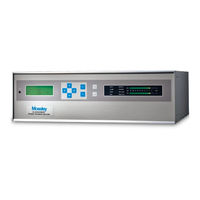
Moseley Starlink SL9003Q User Manual (141 pages)
Digital Studio Transmitter Link
Brand:
Moseley
| Category:
Transmitter
| Size: 2 MB
Table of Contents
Table of Contents
8
Table 1-1. Bit Rate, Threshold, & Bandwidth
13
Figure 2-1. SL9003Q Typical Rack Mount Bracket Installation
18
Figure 2-2. SL9003Q 2 or 4 Channel Digital STL Setup
20
Figure 2-3. SL9003Q Repeater Setup
21
Table 2-1. Encoder/Decoder Typical Settings
23
Figure 2-4. Radio TX Status Performance Check
25
Figure 2-5. RX Modem Status Performance Check
26
Figure 3-1. SL9003Q AC Power Supply
27
Figure 3-2. SL9003Q DC Power Supply
28
Figure 3-3. SL9003Q Discrete Audio Bench Test Setup
30
Figure 3-4. Receiver Site Installation Details
36
Figure 3-5. Rack Ear Bracket Mounting Methods
37
Figure 3-6. Transmitter Antenna Testing
39
Figure 4-1. SL9003Q Front Panel
41
Table 4-1. LED Status Indicator Functions (Transmitter)
42
Table 4-2. LED Status Indicator Functions (Receiver)
43
Table 4-3. LED Status Indicator Functions (Repeater/Full Duplex Systems)
43
Figure 4-2. Main Menu Screen
44
Figure 4-3. Radio Launch Menu Screen Navigation
45
Figure 4-4. Top Level Screen Menu Structure
46
Figure 5-1. Audio Encoder Front Panel
65
Figure 5-2. Audio Decoder Front Panel
66
Figure 5-3. Audio Encoder PC Board / Switch & Jumper Settings
67
Figure 5-4. Audio Decoder PC Board / Switch & Jumper Settings
71
Figure 5-5. AES/EBU-XLR Encoder Connection
74
Figure 5-6. SPDIF-XLR Encoder Connection
74
Figure 5-7. AES/EBU-XLR Decoder Connection
75
Figure 5-8. SPDIF-XLR Decoder Connection
75
Figure 5-9. Data Channel Connector- DSUB (9-Pin)
75
Figure 5-10. QAM Modem Front Panel
76
Figure 5-11. Up/Down Converter Front Panel
77
Figure 5-12. SL9003Q NMS Card
80
Table 5-1. NMS External I/O Pin Descriptions
81
Figure 5-13. NMS Card External I/O Pinout
81
Figure 5-14. Representative Internal Relay Wiring
82
Figure 5-15. NMS External RSL Voltage Curve (Pin 10)
85
Figure 7-1. SL9003Q Transmitter System Block Diagram
91
Figure 7-2. Audio Encoder Block Diagram
92
Figure 7-3. if Upconverter Daughter Card Block Diagram
93
Figure 7-4. Transmit Module (Upconverter) Block Diagram
94
Figure 7-5. SL9003Q RF Power Amplifier Block Diagram
95
Figure 7-6. SL9003Q Receiver System Block Diagram
96
Figure 7-7. Receiver Module Block Diagram
97
Figure 7-8. SL9003Q if Downconverter Daughter Card Block Diagram
98
Figure 7-9. Audio Decoder Block Diagram
99
Table A-1. Typical Antenna Gain
105
Table A-2. Free Space Loss
105
Table A-3. Transmission Line Loss
105
Table A-4. Branching Losses
106
Table A-5. Typical Received Signal Strength Required for BER of 1X10E-4
106
Methods of Improving Reliability
108
Availability Requirements
108
Table A-6. Relationship between System Reliability & Outage Time
108
Table A-7. Fade Margins Required for 99.99% Reliability, Terrain Factor of 4.0, and
108
Path Calculation Balance Sheet
109
Audio Considerations
111
Units of Audio Measurement
111
Why Dbm
111
Audio Meters
111
Voltage-Based Systems
111
Old Habits die Hard
111
Glossary of Terms
113
Microvolt - Dbm - Watt Conversion (50 Ohms
117
Spectral Emission Masks
119
500 Khz Allocation
119
300 Khz Allocation
120
Redundant Backup with TP128, TP64, or TPT-2 Transfer Panels
121
TP128/TP64 System Features
121
TP128/TP64 System Specifications
121
TP128/TP64 Installation
122
TP128/TP64 Rack Installation
122
TP128 Power Supply
122
TP64 Power Supply
122
Equipment Interconnection
122
Starlink SL9003Q Backup Operation
122
Digital STL with Analog STL Backup Using a TPT-2
127
Discrete Starlink with DSP6000 Backup Using a TPT-2
129
Hot/Cold Standby Modes
133
Panel Controls and Indicators
133
Master/Slave Operation & LED Status
134
Table F-1. TP128/TP64 Transmitter Master/Slave Logic
134
Table F-2. TP128/TP64 Receiver Master/Slave Logic
134
Software Settings
135
Starlink Transmitter Settings
135
TP128 Settings
135
TP64 Settings
135
Optimizing Radio Performance for Hostile Environments
137
Table G-1. Interleave Setting Vs. Delay
138
Advertisement
Related Products
Moseley 08MUD1F
Moseley DSP6000A
Moseley Expedio
Moseley PCL-303/C
Moseley PCL-600
Moseley Categories
Transmitter
Remote Control
Radio
Receiver
Measuring Instruments
More Moseley Manuals
Login
Sign In
OR
Sign in with Facebook
Sign in with Google
Upload manual
Upload from disk
Upload from URL