
Related Manuals for Moseley Starlink SL9003Q


Summary of Contents for Moseley Starlink SL9003Q
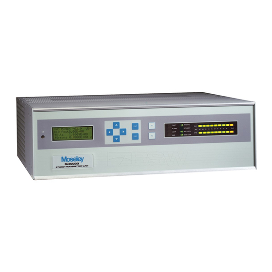
- Page 1 User Manual Starlink SL9003Q Digital Studio Transmitter Link Doc. 602-12016-01 Revision J Released December, 2010 Moseley SL9003Q 602-12016-01 Revision J...
- Page 2 2. In case of any equipment thought to be defective, the purchaser shall promptly notify Moseley Associates, Inc., in writing, giving full particulars as to the defects. Upon receipt of such notice, Moseley Associates, Inc. will give instructions respecting the shipment of the equipment or such other manner as it elects to service this Warranty as above provided.
- Page 3 602-12016-01 November 2005 4.4.1 602-12016-01 November 2005 602-12016-01 November 2005 February 2006 Removed Composite and 4-Port MUX 602-12016-01 October 2007 602-12016-01 February 2008 1.3 reference 5W TX option 602-12016-01 December 2010 Appendix F add TP128 Moseley SL9003Q 602-12016-01 Revision J...
- Page 4 Additional material for reference and design. These include: • Path Evaluation Information • Audio Considerations • Glossary of Terms • Conversion Chart (microvolts to dBm) • Spectral Emission Masks • Redundant Configurations • Use in Hostile Environments • FCC Applications Information Moseley SL9003Q 602-12016-01 Revision J...
- Page 5 Power Requirements................3-11 3.3.3 Rack Mount Installation ..............3-11 Antenna/Feed System ................3-11 3.4.1 Antenna Mounting................3-11 3.4.2 Transmission Line ................3-12 3.4.3 Environmental Seals................3-12 Transmitter Antenna Testing ..............3-13 Link Alignment ..................3-14 Moseley SL9003Q 602-12016-01 Revision J...
- Page 6 5.2.11 Decoder: ISO/MPEG RATE ..............5-7 5.2.12 Decoder: S21 - DATA CHANNEL ............5-8 5.2.13 Decoder: S22 - BOARD ID..............5-8 5.2.14 Decoder: S23 - SYSTEM CONFIG............5-9 5.2.15 Decoder: S32 SYSTEM CONFIG ............. 5-9 Moseley SL9003Q 602-12016-01 Revision J...
- Page 7 A.1.4 K Factors ....................A-2 A.1.5 Path Profiles ................... A-4 A.2 Path Analysis ....................A-4 A.2.1 Overview ....................A-4 A.2.2 Losses ....................A-4 A.2.3 Path Balance Sheet/System Calculations ............ A-4 A.2.4 Path Availability & Reliability ..............A-7 Moseley SL9003Q 602-12016-01 Revision J...
-
Page 8: Table Of Contents
F.3.2 TP128 Power Supply ................F-2 F.3.3 TP64 Power Supply .................. F-2 F.4 Equipment Interconnection................F-2 F.4.1 Starlink SL9003Q Backup Operation ............F-2 F.4.2 Digital STL with Analog STL Backup using a TPT-2........F-7 F.4.3 Discrete Starlink with DSP6000 Backup using a TPT-2 ........F-9 F.5 Operation ....................F-13... - Page 9 Figure 7-8. SL9003Q IF Downconverter Daughter Card Block Diagram......7-8 Figure 7-9. Audio Decoder Block Diagram..............7-9 Figure F-1. Starlink SL9003Q Transmitter Main/Standby Configuration ......F-4 Figure F-2. Starlink SL9003Q RX Main/Standby Connection (w/OPTIMOD)..... F-5 Figure F-3. Receiver Audio Output Switching-External Control (Discrete or Digital Audio) F-6 Figure F-4.
- Page 10 Table A-7. Fade Margins Required for 99.99% Reliability, Terrain Factor of 4.0, and Climate Factor of 0.5 ..................A-8 Table F-1. TP128/TP64 Transmitter Master/Slave Logic ..........F-14 Table F-2. TP128/TP64 Receiver Master/Slave Logic..........F-14 Table G-1. Interleave Setting vs. Delay ..............G-2 Moseley SL9003Q 602-12016-01 Revision J...
- Page 11 Section 1: System Features & Specifications 1. System Features & Specifications System Introduction The Moseley STARLINK 9000 is the first all-digital, open-architecture, modular system for CD-quality audio transmission. The versatility and power of the STARLINK 9000 comes from a complete range of plug-and-play personality modules.
- Page 12 Section 1: System Features & Specifications Specifications Note: Other combinations of frequencies, bandwidths, and output power may be available but not specifically listed here. Please contact Moseley Sales Department for availability. Specifications are subject to change without notice. 1.3.1 System Specifications – Discrete Audio Capacity 4 linear (32 or 44.1 kHz sample rate) + 2 data channels;...
-
Page 13: Table 1-1. Bit Rate, Threshold, & Bandwidth
User Selectable: 16, 32, 64, 128 QAM FCC Emission Type 200KD7W Designation 250KD7W 300KD7W 500KD7W FCC Identifier CSU9WKSL9003Q74 Power Source AC: Universal AC, 90-260 VAC, 47-63 Hz DC: +/- 12 VDC, +/- 24 VDC, +/- 48 VDC, Isolated chassis ground Moseley SL9003Q 602-12016-01 Revision J... - Page 14 XLR male, electronically balanced, low Z/600 ohm selectable Analog Audio Level -10 dBu to +18 dBu, rear panel accessible Digital Audio Output AES/EBU: Transformer balanced, 110 ohm input impedance SPDIF: Unbalanced, 75 ohm input impedance Moseley SL9003Q 602-12016-01 Revision J...
- Page 15 UDP Stream/Ethernet Voice; Low Speed Async Data (RS-232), High Speed Sync Data (V.35, RS-449) Data Rates Low Speed 300-38400 bps; Voice 16, 24, 32, 64 kbps; High Speed to 2040 kbps Trunk V.35 or RS-449 Moseley SL9003Q 602-12016-01 Revision J...
- Page 16 The SL9003Q Transmitter has been granted Equipment Authorization under Part 74 of the FCC Rules and Regulations. Equipment Class: Broadcast Transmitter Base Station Frequency Range: 944-952 MHz Emission Bandwidth: 200 – 500 kHz FCC Identifier: CSU9WKSL9003Q74 Moseley SL9003Q 602-12016-01 Revision J...
- Page 17 Be sure to retain the original boxes and packing material in case of return shipping. Inspect all items for damage and/or loose parts. Contact the shipping company immediately if anything appears damaged. If any of the listed parts are missing, call the distributor or Moseley immediately to resolve the problem. Notices CAUTION DO NOT OPERATE UNITS WITHOUT AN ANTENNA, ATTENUATOR, OR LOAD CONNECTED TO THE ANTENNA PORT.
-
Page 18: Figure 2-1. Sl9003Q Typical Rack Mount Bracket Installation
(or below) the unit for proper air ventilation of the card cage. The rack ears are typically mounted as shown in Figure 2-1. Other mounting methods are possible, as outlined in Section 3, Installation. Figure 2-1. SL9003Q Typical Rack Mount Bracket Installation Moseley SL9003Q 602-12016-01 Revision J... - Page 19 1 UDP Stream data channel, 544 kbps TX /RX Pair (6-Port Mux) Repeater No Audio Channels No Data Channels Full Duplex Repeater Up to 4 Audio Channels Drop Only 1 data channel drop available Full Duplex (using Audio Decoder) Moseley SL9003Q 602-12016-01 Revision J...
-
Page 20: Figure 2-2. Sl9003Q 2 Or 4 Channel Digital Stl Setup
Section 2: Quick Start Figure 2-2. SL9003Q 2 or 4 Channel Digital STL Setup Moseley SL9003Q 602-12016-01 Revision J... -
Page 21: Figure 2-3. Sl9003Q Repeater Setup
The LCD screen (RADIO TX CONTROL) selects the power-up state and controls the radiate function of the TX unit. The unit powers up to the MAIN MENU: • Scroll Down to RADIO and press ENTER. • Configure the launch screen for CONTROL TX. Moseley SL9003Q 602-12016-01 Revision J... - Page 22 Transmitter in standby mode. • Press ESC to accept the setting. • If you change anything from the original power-up setting, you will see the following screen: • Choose YES and press ENTER to accept. Moseley SL9003Q 602-12016-01 Revision J...
-
Page 23: Table 2-1. Encoder/Decoder Typical Settings
LCD screens will list the unit’s RF telemetry values and will be specific to your unit. Frequency (MHz) Power Output Average (Watts) PA Current (Amps) 160-240 300-512 800-960 1340 - 1520 1650-1700 Moseley SL9003Q 602-12016-01 Revision J... - Page 24 Use the RADIO TX STATUS screens to check the SL9003Q Transmitter performance parameters. Figure 2-4 outlines the navigation to the LCD Screens and gives typical readings. Be sure to check the Test Data Sheet for the actual factory readings from your particular unit. Moseley SL9003Q 602-12016-01 Revision J...
-
Page 25: Figure 2-4. Radio Tx Status Performance Check
Section 2: Quick Start Figure 2-4. Radio TX Status Performance Check Moseley SL9003Q 602-12016-01 Revision J... -
Page 26: Figure 2-5. Rx Modem Status Performance Check
This Quick Start section is intended for the experienced user to get the studio-transmitter link up and running. Less experienced users should read the entire manual prior to installation. If problems still exist for your application, do not hesitate to call Moseley Technical Services for assistance. -
Page 27: Figure 3-1. Sl9003Q Ac Power Supply
The power supply module can be removed from the unit and a cage protects service personnel from high voltage. The power supply is fan cooled to increase reliability. The module supplies +12 V, +5 V, and +10 V for the PA (TX). Figure 3-1. SL9003Q AC Power Supply Moseley SL9003Q 602-12016-01 Revision J... -
Page 28: Figure 3-2. Sl9003Q Dc Power Supply
The DC input is isolated from chassis ground and can be operated in a positive or negative ground configuration. The power supply module is removable from the unit and no high voltages are accessible. Figure 3-2. SL9003Q DC Power Supply Moseley SL9003Q 602-12016-01 Revision J... - Page 29 (Failure to observe these precautions can cause the transmitter final amplifier to be destroyed or the receiver preamplifier to be damaged) ■ Avoid excessive pressure on the audio adjustment potentiometers located on the back panels of the audio encoder/decoder modules. Moseley SL9003Q 602-12016-01 Revision J...
-
Page 30: Figure 3-3. Sl9003Q Discrete Audio Bench Test Setup
RF Wattmeter: 950 MHz operation with a measurement range of 1–5 Watts • RF Power Attenuator: 50 ohm, 5 watt “dummy load” for 950 MHz operation with 20 to 30 dB of attenuation • Variable Step Attenuator: 0–100 dB at 950 MHz Moseley SL9003Q 602-12016-01 Revision J... - Page 31 FLASHING RED indicates no signal (NON-OPERATIONAL) 6) After verifying the DEMOD LED is within the color range, go to the QAM RADIO RX STATUS screen on the front panel LCD and page down to the RSL parameter (see below). Moseley SL9003Q 602-12016-01 Revision J...
- Page 32 (-60 dBm typical). 8) Press ESC until you arrive at the Main Menu. Follow the screen navigation below to get to the QAM MODEM STATUS (Post-BER) screen on the front panel LCD. Moseley SL9003Q 602-12016-01 Revision J...
- Page 33 RF Wattmeter: 950 MHz operation with a measurement range of 1–5 Watts • RF Power Attenuator: 50 ohm, 5 watt “dummy load” for 950 MHz operation with 20 to 30 dB of attenuation • Variable Step Attenuator: 0–100 dB at 950 MHz Moseley SL9003Q 602-12016-01 Revision J...
- Page 34 The installation of the SL9003Q involves several considerations. A proper installation is usually preceded by a pre-installation site survey of the facilities. The purpose of this survey is to familiarize the customer with the basic requirements needed for the installation to go Moseley SL9003Q 602-12016-01 Revision J...
- Page 35 SL9003Q in an area where it is protected from the weather and as close to the antenna as possible. Locate the power source and verify that it is suitable for proper installation. Moseley SL9003Q 602-12016-01 Revision J...
-
Page 36: Figure 3-4. Receiver Site Installation Details
3-10 Section 3: Installation Figure 3-4. Receiver Site Installation Details Moseley SL9003Q 602-12016-01 Revision J... -
Page 37: Figure 3-5. Rack Ear Bracket Mounting Methods
The antennas used as part of the SL9003Q system are directional. The energy radiated is focused into a narrow beam by the transmitting antenna and must be aligned towards the receiving antenna. The type of antenna used in a particular installation will depend on Moseley SL9003Q 602-12016-01 Revision J... - Page 38 Tape ends must be cut rather than torn—a torn end will unravel and work loose in the wind. Use plenty of tape for protection against water penetration and the premature replacement of the transmission line. Moseley SL9003Q 602-12016-01 Revision J...
-
Page 39: Figure 3-6. Transmitter Antenna Testing
• Connect the radio end of the transmission line to a wattmeter (with appropriate frequency and power rating), using the radio feed line and another coaxial jumper (see Figure 3-6). Moseley SL9003Q 602-12016-01 Revision J... - Page 40 After peak alignment is achieved, tighten the bolts to hold the antenna securely. Double- check the RSL and BER STATUS indications. Link alignment is complete. Moseley SL9003Q 602-12016-01 Revision J...
-
Page 41: Figure 4-1. Sl9003Q Front Panel
Contrast Adjustment: The contrast adjustment is front panel accessible (to the left of the LCD). Use a small flathead screwdriver to adjust for optimum visual clarity. 4.2.2 Cursor and Screen Control Buttons The buttons on the SL9003Q front panel are used for LCD screen interface and control functions: Moseley SL9003Q 602-12016-01 Revision J... -
Page 42: Table 4-1. Led Status Indicator Functions (Transmitter)
GREEN indicates the transmitter is radiating and the RF output (forward power) is above the factory-set threshold. STANDBY Standby GREEN indicates the transmitter is ready and able for radiate to be enabled. AFC LOCK AFC Lock GREEN indicates the 1st LO is phase-locked. Moseley SL9003Q 602-12016-01 Revision J... -
Page 43: Table 4-2. Led Status Indicator Functions (Receiver)
GREEN indicates BER is within acceptable limits. AFC Lock GREEN indicates the 1st LO is phase-locked.. LOCK Demodulator GREEN indicates the QAM Demodulator is locked and functional. LOCK Lock Table 4-3. LED Status Indicator Functions (Repeater/Full Duplex Systems) Moseley SL9003Q 602-12016-01 Revision J... -
Page 44: Figure 4-2. Main Menu Screen
Radio Launch Screen: The RADIO LAUNCH screen allows you to quickly get to a particular screen within a functional grouping in the unit. The logic is slightly different than other screens. Figure 4-3 shows the details for locating the desired Radio Screen. Moseley SL9003Q 602-12016-01 Revision J... -
Page 45: Figure 4-3. Radio Launch Menu Screen Navigation
In general, <ENTER> will take you to the next screen from a menu choice, <UP> or <DOWN> will scroll through screens within a menu choice, and <ESC> will take you back up one menu level. Certain configuration screens have exceptions to this rule, and are noted later in this section. Moseley SL9003Q 602-12016-01 Revision J... -
Page 46: Figure 4-4. Top Level Screen Menu Structure
4.4.1 Meter Function Settings Summary Bargraph ENCDR1, 2, … Selects the audio source for display on the audio level DECDR1, 2, … bargraph NONE Turns off the bargraph LED Dsp Used for future option Moseley SL9003Q 602-12016-01 Revision J... - Page 47 Defines Unit # for network ID SECURITY Indicates access level of security: Lockout No control available User (default) Limited control of parameters Factory Full configure and calibration FIRMWARE V.x.xx Revision of front panel screen menu software Moseley SL9003Q 602-12016-01 Revision J...
- Page 48 The Factory Calibration Screens are documented below. You may refer to this diagram when instructed to do so by Moseley customer service technicians. Although you can access the factory calibration menus for field service and monitoring of certain measurements, be aware that changing any parameter (pressing ENTER) may cause the units to fail to operate properly.
- Page 49 Section 4: Operation Figure 4-5. Factory Calibration-Radio TX Screens Figure 4-6. Factory Calibration-Radio RX Screens Moseley SL9003Q 602-12016-01 Revision J...
- Page 50 4-10 Section 4: Operation Figure 4-7. Factory Calibration-QAM Modem Screens Figure 4-8. Factory Calibration-System Screens Moseley SL9003Q 602-12016-01 Revision J...
- Page 51 Defines Unit # for network ID MAIN TITLE TRANSMITTER Determines main menu display and affects screen menu RECEIVER selection of modules TRANSCEIVER DTV Link NXE1 DS3 TX DS3 RX DS3 XC EXP RX EXP TX Redundant Chooses redundant supply option Moseley SL9003Q 602-12016-01 Revision J...
- Page 52 Sets the system date used for NMS and Fault/Alarm logging Month 01-12 After selection, press ENTER to save Year 00-99 Hour 00-23 Sets the system time used for NMS and Fault/Alarm logging Minutes 00-59 After selection, press ENTER to save Seconds 00-59 Moseley SL9003Q 602-12016-01 Revision J...
- Page 53 OUTPUT *RX SIG LVL Controls monitoring output source of pin 10 on Ext OUTPUT *TX FWD PWR I/O high-density connector. OUTPUT *Rev PWR Receiver: Received Signal Level 0-5 Vdc OUTPUT *BER Transmitter: Transmit Power 0-5 Vdc Moseley SL9003Q 602-12016-01 Revision J...
- Page 54 Logging: All fault and alarm events are logged with the date and time. Fault screen reset: After viewing the screen, press ENTER to clear all logs entries. If the fault has been corrected, no new logs will be generated. Moseley SL9003Q 602-12016-01 Revision J...
- Page 55 Confirms 70 MHz IF synthesizer is phase locked UNLOCK 1.8 VDC (nominal) 70 MHz IF synthesizer AFC voltage IFOUT 100% (nominal) IF output level Mode 16Q (nominal) Modulation mode 128Q 256Q QPSK BAUD xxx.x k Symbol rate xxxx k Data rate Moseley SL9003Q 602-12016-01 Revision J...
- Page 56 NOTE: Pre-BER may indicate a static (non-zero) error rate under normal operation, depending on the QAM mode, especially in the higher QAM modes of operation such as 32 QAM and 64 QAM resulting from transmitter power amplifier IMD. This is normal. Moseley SL9003Q 602-12016-01 Revision J...
- Page 57 Press ENTER to clear the screen. x.xxxE+xx Severely Errored Seconds UNAS x.xxxE+xx Unavailable Seconds BAUD LOCK (default) Indicates modulator PLL is locked to incoming data clock UNLOCK LOCK (default) Indicates FEC decoder is synchronized UNLOCK Moseley SL9003Q 602-12016-01 Revision J...
- Page 58 128Q 256Q QPSK BAUD xxx.x K Symbol rate xxxx K Data rate Encoding mode SPCTR NRML Spectrum Normal or Invert FLTR xx % Nyquist filter INTRL Interleave Depth 4.4.12.4 Radio Modem Status - Common Screens Moseley SL9003Q 602-12016-01 Revision J...
- Page 59 IC firmware Version 4.4.13 Radio TX Status Function Settings Summary Freq A 948.0000 MHz Displays the transmitter output carrier frequency XMTR Status of transmitter: TRAFFIC ON in a hot standby mode FORCED (default) Forced ON Moseley SL9003Q 602-12016-01 Revision J...
- Page 60 Class-A amplifier. Class-C power amplifiers used with analog FM STLs will not work. The post-amplifier compression point should be between 6 dB (16 QAM) and 9 dB (64 QAM) higher than the expected average transmit power. Moseley SL9003Q 602-12016-01 Revision J...
- Page 61 100% (nominal) LO relative power level 4.4.15 Radio TX Control Function Settings Summary TX Radiate AUTO (default) Transmitter radiating, but folds back output power on high antenna VSWR (REV PWR) Transmitter radiating Transmitter not radiating Moseley SL9003Q 602-12016-01 Revision J...
- Page 62 51,4 valid for full duplex modem only 68,3 valid for full duplex modem only 102,2 valid for full duplex modem only 204,1 valid for full duplex modem only SPECTRUM NORMAL (default), INVERT Moseley SL9003Q 602-12016-01 Revision J...
- Page 63 RECOVERED Recovered Clock INTERNAL Internal Clock Clk Phase: Normal Normal Inverted Inverted 4.4.18 Radio TX Configure Function Settings Summary FREQ 950.5000 MHz Displays the frequency of the transmitter and allows you to make frequency changes. Moseley SL9003Q 602-12016-01 Revision J...
- Page 64 NMS/CPU PC Interface Software The NMS/CPU card is configured with Windows-based PC software. The hardware is accessed through the serial port on the NMS card back panel. A separate manual is available for operational details of this interface. Moseley SL9003Q 602-12016-01 Revision J...
-
Page 65: Figure 5-1. Audio Encoder Front Panel
The Audio Decoder accepts the data streams from the QAM demodulator or MUX. The data is decoded for linear (or MPEG) stereo digital audio output. D/A conversion is performed for the analog outputs. An auxiliary data channel is available. Moseley SL9003Q 602-12016-01 Revision J... -
Page 66: Figure 5-2. Audio Decoder Front Panel
Switch and jumper settings for the Audio Encoder and Audio Decoder are shown in Figures 5-3 and 5-4, respectively. The following sections describe the groupings of switches. CAUTION: Avoid excessive pressure on the audio adjustment potentiometers located on the back panels of the Audio Encoder/Decoder modules. Moseley SL9003Q 602-12016-01 Revision J... -
Page 67: Figure 5-3. Audio Encoder Pc Board / Switch & Jumper Settings
0 (default) +10 dBu (default) +4 dBu -10 dBu -30 dBu 5.2.2 Encoder: MPEG - ENCODER A SWITCHES ISO/MPEG Input Rate 44.1 kHz 48.0 kHz (default) 32.0 kHz RESERVED A0/A1/A2/A3/A4/A5: These switches should always be OFF (reserved) Moseley SL9003Q 602-12016-01 Revision J... - Page 68 ON (1) ON (1) ON (1) ON (1) Reserved M6/M7: Reserved. Set to OFF (0). 5.2.5 Encoder: S21 - DATA CHANNEL D1/D2: Aux Data # of Bits 6 (6N/5E/5O) 7 (7N/6E/6O) 8 (8N/7E/7O) DEFAULT 9 (9N/8E/8O) Moseley SL9003Q 602-12016-01 Revision J...
- Page 69 R3: This switch selects the Bus Master Clock: OFF=Receive Clock from Mux Bus (default), ON=Supply Clock to Mux Bus. R4: This switch selects Aux RS-232 Data: OFF=Diabled, ON=Enabled (default). R5/R6: These switches select 2-/4-Channel options: 2-/4-Channel Select 2-Channel Reserved 4-Channel Master (1st Pair) Moseley SL9003Q 602-12016-01 Revision J...
- Page 70 Linear Data Rate 44.1 kHz 48.0 kHz 32.0 kHz (default) 44.0 kHz 5.2.9 Encoder: S81 - AES/EBU S81-A S81-B S81-C S81-D S81-E Selection AES/EBU (default) SPDIF Error Flag Selections: S81-VERF S81-ERF Selection Validity Bit and Error Flag Moseley SL9003Q 602-12016-01 Revision J...
-
Page 71: Figure 5-4. Audio Decoder Pc Board / Switch & Jumper Settings
ON (1) ON (1) 112 kb/s ON (1) OFF (0) OFF (0) OFF (0) 128 kb/s ON (1) OFF (0) OFF (0) ON (1) 160 kb/s ON (1) OFF (0) ON (1) OFF (0) 192 kb/s Moseley SL9003Q 602-12016-01 Revision J... - Page 72 The 9600, 19200, and 38400 selections must use CTS Line. D6: This switch is reserved. D7: This switch selects the test mode: OFF=Disabled (default), ON=Enabled. D8: This switch selects the debug mode: OFF=Normal (default), ON=Enabled. 5.2.13 Decoder: S22 - BOARD ID Board# Base Address Moseley SL9003Q 602-12016-01 Revision J...
- Page 73 M5/M6: These switches select the VCO Clock Source as shown in the following table: VCO Clock Source Trunk Compressed Trunk Linear Mux Compressed Mux Linear M7/M8: These switches select the VCO Rate and Clock Frequency: VCO Rate Clock Frequency 44.1K Hz 11.286 MHz Moseley SL9003Q 602-12016-01 Revision J...
-
Page 74: Figure 5-5. Aes/Ebu-Xlr Encoder Connection
The AES/EBU setting is the factory default. The following wiring diagrams should be followed for the proper level and phasing: XLR (female) Ground (HOT) Figure 5-5. AES/EBU-XLR Encoder Connection XLR (female) Ground (HOT) Figure 5-6. SPDIF-XLR Encoder Connection Moseley SL9003Q 602-12016-01 Revision J... -
Page 75: Figure 5-7. Aes/Ebu-Xlr Decoder Connection
Switch S22 sets the Board ID number and Base Address. DO NOT change these switches. 5.2.22 System Configuration Switches S23, S31, and S52 set the board configuration for operation in the system. DO NOT change these switches. Moseley SL9003Q 602-12016-01 Revision J... -
Page 76: Figure 5-10. Qam Modem Front Panel
Figure 5-10. QAM Modem Front Panel IF Card Upconverter/Downconverter There are no user adjustments on this card. All calibrations are factory-set, and configuration settings are controlled remotely by software (via the front panel or serial port). Moseley SL9003Q 602-12016-01 Revision J... -
Page 77: Figure 5-11. Up/Down Converter Front Panel
The carrier frequency of the transmitter can be changed via the front panel within a 20 MHz range without internal adjustment or realignment. 1. Power-up the unit and navigate the LCD screens as follows and press ENTER: Moseley SL9003Q 602-12016-01 Revision J... - Page 78 The carrier frequency of the receiver can be changed via the front panel within a 20 MHz range without internal adjustment or realignment. 1. Power-up the unit and navigate the LCD screens as follows and press the <ENTER> button. Moseley SL9003Q 602-12016-01 Revision J...
- Page 79 4. Follow the Factory Calibration menu tree. Navigate to the QAM Modem and enter the OCXO screen. Enable CW Mode to ON. This will disable modulation on the carrier so that the carrier frequency can be measured. 5. Measure the frequency. Set the CW Mode to OFF. Moseley SL9003Q 602-12016-01 Revision J...
-
Page 80: Figure 5-12. Sl9003Q Nms Card
Monitoring the received signal level with a voltmeter helps facilitate antenna alignment. Long-term link and path statistics are obtained by logging RSL fade and BER data. Moseley SL9003Q 602-12016-01 Revision J... -
Page 81: Figure 5-13. Nms Card External I/O Pinout
Figure 5-13. NMS Card External I/O Pinout 5.8.2 Relay Electrical Interface Relays 1 to 4 (pins 8 through 1 on I/O connector, respectively) are solid-state rather than mechanical relays. The following illustration is a schematic diagram of a representative relay interface. Moseley SL9003Q 602-12016-01 Revision J... -
Page 82: Figure 5-14. Representative Internal Relay Wiring
1) On the SL9003Q Tx Main Menu, use Up or Down arrow to select System 2) Press the <ENTER> button. 3) Scroll down to Unit-Wide Parameters 4) Press the <ENTER> button. 5) Scroll up once then down twice to select Mapping 6) Press the <ENTER> button. Moseley SL9003Q 602-12016-01 Revision J... - Page 83 Relay 2: pins 5 (-) and 6 (+) • Any Fault or Alarm or Equipment Power Off: Relay 2 = Off (Set Open) • No Faults or Alarms and Equipment Power On: Relay 2 = On (Set Closed) Moseley SL9003Q 602-12016-01 Revision J...
- Page 84 Relay 2: pins 5 (-) and 6 (+) • One or more Transmitter Alarm Status Exist or Equipment Power Off: Relay 2 = Off (Set Open) • No Transmitter Alarm Status Exist and Equipment Power On: Relay 2 = On (Set Closed) Moseley SL9003Q 602-12016-01 Revision J...
-
Page 85: Figure 5-15. Nms External Rsl Voltage Curve (Pin 10)
Figure 5-15 shows the representative output characteristic for the receiver RSL. Starlink Ext. NMS Voltage (Pin10) vs. Received Signal Level -105 Received Signal Level (dBm) Figure 5-15. NMS External RSL Voltage Curve (Pin 10) Moseley SL9003Q 602-12016-01 Revision J... - Page 86 5-22 Section 5: Module Configuration Moseley SL9003Q 602-12016-01 Revision J...
- Page 87 6. Customer Service Introduction Moseley Associates will assist its product users with difficulties. Most problems can be resolved through telephone consultation with our technical service department. When necessary, factory service may be provided. If you are not certain whether factory service of your equipment is covered, please check your product Warranty/Service Agreement.
- Page 88 Spare Parts Kits Spare parts kits are available for all Moseley Associates products. We encourage the purchase of the appropriate kits to allow self-sufficiency with regard to parts. Information about spares kits for your product may be obtained from our sales department or technical service department.
- Page 89 For long term quality, inspect each solder joint – top and bottom – under a magnifier and rework solder joints to meet industry standards. Inspect the adjacent components soldered by the Moseley Associates production line for an example of high reliability soldering. Moseley SL9003Q...
- Page 90 Section 6: Customer Service Moseley SL9003Q 602-12016-01 Revision J...
-
Page 91: Figure 7-1. Sl9003Q Transmitter System Block Diagram
The SL9003Q TX is a modular digital radio transmitter system that operates in multiple RF bands (160-240, 330-512, 800-960, 1340-1520, and 1650-1700 MHz) and provides simplex data transmission up to 2.048 Mbps increments in 8 kbps steps. The block diagram in Figure Moseley SL9003Q 602-12016-01 Revision J... -
Page 92: Figure 7-2. Audio Encoder Block Diagram
Analog Input daughtercard), and these inputs are converted to 16/24 bit digital stereo data. The SRC (sample rate converter) passes the digital audio data stream to a data multiplexer while synchronizing/converting the incoming sample rate (30-50 kHz) to the Moseley SL9003Q 602-12016-01 Revision J... -
Page 93: Figure 7-3. If Upconverter Daughter Card Block Diagram
6.4 MHz, adding FEC (Forward Error Correction) bits while interleaving the blocks of data. The result is a very spectrally efficient, yet robust linear modulation scheme. This process requires an ultra-stable master clock provided by an OCXO (oven controlled crystal oscillator) that is accurate to within 0.1 ppm. Moseley SL9003Q 602-12016-01 Revision J... -
Page 94: Figure 7-4. Transmit Module (Upconverter) Block Diagram
The ALC monitors the PA forward power (FWD) output sample, and controls the Upconverter gain per an algorithm programmed in the CPU. The ALC also controls the power-up RF conditions of the transmitter output. Moseley SL9003Q 602-12016-01 Revision J... -
Page 95: Figure 7-5. Sl9003Q Rf Power Amplifier Block Diagram
(160-240, 330-512, 800-960, 1340-1520, and 1650-1700 MHz) and provides simplex data transmission up to 2.048 Mbps increments in 8 kbps steps. The block diagram in Figure 7-6 shows the operational block partitions that also represent the physical partitions within the system. Moseley SL9003Q 602-12016-01 Revision J... -
Page 96: Figure 7-6. Sl9003Q Receiver System Block Diagram
Module settings are loaded into the installed cards. Power-up default settings are stored in non-volatile memory. LCD menu software is uploaded into memory, providing field upgrade capability. A Windows-based PC interface is available for connection at the rear panel DATA port. Moseley SL9003Q 602-12016-01 Revision J... -
Page 97: Figure 7-7. Receiver Module Block Diagram
RF signals resulting from RF bandwidth that is much wider than the IF bandwidth. The linear QAM scheme is fairly intolerant of amplifier overload. These problems are typically related to difficult radio interference environments that include high power pagers, cellular phone sites, and vehicle location systems. Moseley SL9003Q 602-12016-01 Revision J... -
Page 98: Figure 7-8. Sl9003Q If Downconverter Daughter Card Block Diagram
The MUX is documented in a separate user manual. Typical broadcast applications are described here: 6-Port Mux: For discrete STL systems, the 6-port mux (with Ethernet option card) is primarily used to interface and demultiplex the Ethernet data stream from the QAM demodulator. Moseley SL9003Q 602-12016-01 Revision J... -
Page 99: Figure 7-9. Audio Decoder Block Diagram
The SRC receives the data stream via the second data multiplexer. This information is compared to the clock rate determined at switches M7 and M8 for conversion to the final output decoding segment. Moseley SL9003Q 602-12016-01 Revision J... - Page 100 This information is then sent to the SRC for conversion of the incoming data to the rate of desired output. Moseley SL9003Q 602-12016-01 Revision J...
- Page 101 A.1 Introduction Please visit www.moseleybroadcast.com and click on support for online Path Evaluation resources or simply telephone Moseley Customer Services for help in this area. A.1.1 Line-of-Sight For the proposed installation sites, one of the most important immediate tasks is to determine whether line-of-sight is available.
- Page 102 K times that of earth's actual radius. The K factor in propagation is thus the ratio of effective earth radius to actual earth radius. The K factor depends on the rate of change of refractive index with height and is given as: Moseley SL9003Q 602-12016-01 Revision J...
- Page 103 K = 1.33 and CF = 1.0 F1 • K = 1.0 and CF = 0.6 F1 • K = 0.67 and CF = 0.3 F1 Where CF is the Fresnel zone clearance and F1 is the first Fresnel zone radius. Moseley SL9003Q 602-12016-01 Revision J...
- Page 104 A.2.3 Path Balance Sheet/System Calculations A typical form for recording the gains and losses for a microwave path is shown in Section A.2.7. The purpose of this tabulation is to determine the fade margin of the proposed radio Moseley SL9003Q 602-12016-01 Revision J...
-
Page 105: Table A-1. Typical Antenna Gain
4.6 dB 2.4 dB 450 MHz 5.5 dB 2.9 dB 470 MHz 5.7 dB 3.0 dB 950 MHz 8.3 dB 4.6 dB Line 7: Enter the total receiver transmission line loss (see Table A-3 above). Moseley SL9003Q 602-12016-01 Revision J... -
Page 106: Table A-4. Branching Losses
Line 18: Enter the Climate Factor. b (climate factor) = 1/2 for Gulf coast or similar hot, humid areas. = 1/4 for normal interior temperate or northern regions. = 1/8 for mountainous or very dry areas. Moseley SL9003Q 602-12016-01 Revision J... - Page 107 = ryr x 10-F/10 = b x rm x 10-F/10 = a x b x 2.5 x 10⁻⁶ x f x 10D3 x 10-F/10 The following table shows the relationship between system reliability and outage time. Moseley SL9003Q 602-12016-01 Revision J...
-
Page 108: Methods Of Improving Reliability
17 dB 20 dB 15 Miles (24 km) 22 dB 25 dB 20 Miles (32 km) 27 dB 30 dB 25 Miles (40 km) 29 dB 32 dB 30 Miles (48 km) 32 dB 35 dB Moseley SL9003Q 602-12016-01 Revision J... -
Page 109: Path Calculation Balance Sheet
Appendix A: Path Evaluation Information A.2.7 Path Calculation Balance Sheet Moseley SL9003Q 602-12016-01 Revision J... - Page 110 A-10 Appendix A: Path Evaluation Information Moseley SL9003Q 602-12016-01 Revision J...
-
Page 111: Audio Considerations
5.0 Volts would probably not even be within the trim pot adjustment range for 0 VU. So, a good general rule when working with modern audio equipment unless you know it to be terminated in 600 Ohms is to read the manufacturer’s “dBm” as “dBu”. Moseley SL9003Q 602-12016-01 Revision J... - Page 112 Appendix B: Audio Considerations (Reprinted from the ATS-1 User’s Manual, published in July 1994, with permission from Audio Precision, Inc., located in Beaverton, Oregon) Moseley SL9003Q 602-12016-01 Revision J...
-
Page 113: Glossary Of Terms
Decibel relative to 1 mW Decibel relative to .775 Vrms Data Circuit-Terminating Equipment Digital Signal Processing DSTL Digital Studio-Transmitter Link Data Terminal Equipment Digital Voltmeter Electromagnetic Interference Electrostatic Discharge/Electrostatic Damage Field effect transistor Frequency Modulation Oscillator Moseley SL9003Q 602-12016-01 Revision J... - Page 114 Intermodulation Distortion ISDN Integrated-Services Digital Network Kbps Kilobits per second Kilohertz Light-emitting diode LO, LO1 Local oscillator, first local oscillator Least significant bit Moseley Associates, Inc. Mbps Megabits per second Modem Modulator-demodulator Millisecond Most significant bit Multiplex, Multiplexer Microsecond Microvolts...
- Page 115 Security Control and Data Acquisition Signal-to-Noise Ratio Step Recovery Diode Studio-Transmitter Link Time Division Multiplexing Total harmonic distortion Test Point Transistor-transistor logic Transmitter Vrms Volts root-mean-square Volts peak Vp-p Volts peak-to-peak VRMS Volts, root-mean-square VSWR Voltage standing-wave ratio Moseley SL9003Q 602-12016-01 Revision J...
- Page 116 Appendix C: Glossary of Terms Term Definition Input Impedance ZOUT Output Impedance Moseley SL9003Q 602-12016-01 Revision J...
-
Page 117: Microvolt - Dbm - Watt Conversion (50 Ohms
Appendix D: Microvolt – dBm – Watt Conversion (50 ohms) Microvolt – dBm – Watt Conversion (50 ohms) Moseley SL9003Q 602-12016-01 Revision J... - Page 118 Appendix D: Microvolt – dBm – Watt Conversion (50 ohms) Moseley SL9003Q 602-12016-01 Revision J...
-
Page 119: Spectral Emission Masks
The following spectral compliance emission plots are peak power measurements at 1 watt average transmit power. E.1 500 kHz Allocation a. 1408 kbps @ 16 QAM b. 1536 kbps @ 16 QAM c. 1536 kbps @ 64 QAM Moseley SL9003Q 602-12016-01 Revision J... -
Page 120: 300 Khz Allocation
Appendix E: Spectral Emission Masks d. 2048 Kbps @ 64 QAM E.2 300 kHz Allocation a. 1408 kbps @ 64 QAM E.3 250 KHz Allocation a. 1024 kbps @ 64 QAM Moseley SL9003Q 602-12016-01 Revision J... -
Page 121: Redundant Backup With Tp128, Tp64, Or Tpt-2 Transfer Panels
Appendix F: Redundant Backup with TP64 and TPT-2 Transfer Panels Redundant Backup with TP128, TP64, or TPT-2 Transfer Panels The Starlink SL9003Q can operate in a redundant hot or cold standby configuration STL link using the TP128 orTP64 Transfer Panel for transmitter switching. The Starlink digital STL link may also be used in a redundant cold standby configuration with an existing analog STL as a main or backup link when using a TPT-2 Transfer Panel. -
Page 122: Tp128/Tp64 Installation
STARLINK STL transmitters in a redundant standby retrofit are relatively simple to setup in the field. The system installer can call Moseley Technical Services for assistance, if required. F.3.1 TP128/TP64 Rack Installation The TP128/TP64 Transfer Panel is normally mounted between the Main and Standby radios to allow the shortest possible lengths of transmission cable. - Page 123 The RS-232 data control aux channel can be split to both transmitters through a “modem splitter”. The splitter can be a passive device, such as Black Box P/N TLO73A-R2 (3 port, MS-3). Figure F-1. Starlink SL9003Q with TP128 Transmitter Main/Standby Configuration Moseley SL9003Q 602-12016-01 Revision J...
- Page 124 Appendix F: Redundant Backup with TP64 and TPT-2 Transfer Panels Figure F-2. Starlink SL9003Q with TP64 Transmitter Main/Standby Configuration Receiver: Figures F-3 and F-4 show a typical Starlink QAM (STL) Main/Standby configuration for the receiver end of the link. A TP64 is not required, as both of the receivers are ALWAYS ON.
- Page 125 Appendix F: Redundant Backup with TP64 and TPT-2 Transfer Panels Figure F-3. Starlink SL9003Q RX Main/Standby Connection (w/OPTIMOD) Receiver Audio Switching - External: If there is no Optimod (or similar) stereo generator/processor at the receiver end of the link, or it is desirable to use common discrete or AES/EBU audio, an external audio switching router can be used to select the active audio feed.
- Page 126 The Main Receiver provides control logic from the RJ45 connector (XFER) on the NMS card for switching the signal to the switcher/router. The Main receiver control line (RJ45 pin 6) will be HIGH (+5V) to indicate the Main receiver is healthy and router input 1 will be Moseley SL9003Q 602-12016-01 Revision J...
-
Page 127: Digital Stl With Analog Stl Backup Using A Tpt-2
Composite vs. Discrete Audio: The other issue is most typical PCL6000/606 links are set for composite FM transmission. The Starlink SL9003Q is a discrete audio link and does not support this type of composite baseband. The Starlink Digital Composite STL must be used if intended to operate as a backup with a composite analog system. - Page 128 Appendix F: Redundant Backup with TP64 and TPT-2 Transfer Panels Figure F-5. Starlink TX & RX NMS-Transfer I/O Connection Moseley SL9003Q 602-12016-01 Revision J...
-
Page 129: Discrete Starlink With Dsp6000 Backup Using A Tpt-2
Set the Starlink system to operate in Cold-Standby mode. In this mode the transmitter is not radiating unless selected to correspond to the TPT-2 operation. The Starlink-to-TPT-2 transfer control cable is available from Moseley for this configuration (203-12225-01). However, a cable can be made from a shielded RJ-45 (Black Box P/N EVNSL60-0006). - Page 130 Receiver Audio Switching – with Optimod Audio Processor: The Main and Standby audio outputs can be routed to the inputs of an Orban Optimod stereo generator (with the AES/EBU input option) or similar device. Route the AES/EBU from the Main receiver and the Moseley SL9003Q 602-12016-01 Revision J...
- Page 131 AES/EBU audio, an external audio switching router can be used to select the active audio feed. The Broadcast Tools SS 2.1/Terminal III switcher/router is shown below in this application (Figure F-8). Moseley SL9003Q 602-12016-01 Revision J...
- Page 132 The Starlink Receiver acting as the main receiver provides control logic from the RJ45 connector (XFER) on the NMS card for switching the signal to the switcher/router. The Starlink receiver control line (RJ45 pin 6) will be HIGH (+5V) to indicate the main receiver is Moseley SL9003Q 602-12016-01 Revision J...
-
Page 133: Hot/Cold Standby Modes
The lid must be removed from the router to set the DIP Switch 5–6 to the ON position for remote control. The transfer control cable is available from Moseley for this configuration (203-12416-01). However, a cable can be made from a shielded RJ-45 (Black Box P/N EVNSL60-0006). This is a 6-foot cable that can be cut and the ends tinned to provide the RX XFER OUT signal (RJ45 pin 6) for the indicated connection. -
Page 134: Master/Slave Operation & Led Status
You may want to put more “time” on the standby unit after an extended period of service. In Hot Standby configurations, this will not improve reliability. In a Cold Standby, the “burn time” is more significant, since the RF power amplifier device operating life becomes a factor. Moseley SL9003Q 602-12016-01 Revision J... -
Page 135: Software Settings
TP128 manual for further details. F.6.2 TP64 Settings The TP64 software settings are contained in the internal firmware. Aside from the front panel RADIO A/B Master Select (described above), there are no user-configurable settings in the TP64 unit. Moseley SL9003Q 602-12016-01 Revision J... - Page 136 F-16 Appendix F: Redundant Backup with TP64 and TPT-2 Transfer Panels Figure F-11. STARLINK – TP64 Control Cable Adaptor 230-12127-01 Moseley SL9003Q 602-12016-01 Revision J...
-
Page 137: Optimizing Radio Performance For Hostile Environments
ISM band may require a more aggressive configuration. The SL9003Q continues in Moseley’s reputation for robust radio products that handle difficult environments. The SL9003Q can be configured for optimal performance from the benign to the most brutal environments directly from the front panel. -
Page 138: Table G-1. Interleave Setting Vs. Delay
Pre-BER is a good indicator of proper circuit operation such as whether the power amplifier is being driven too hard. An increase of only 1 dB above the factory- calibrated level can be enough to cause a substantial pre-corrected error increase. For this Moseley SL9003Q 602-12016-01 Revision J... - Page 139 But for extremely powerful near band interference such as pagers this pre- selector may not provide adequate protection. Moseley has a wealth of experience in specifying filters for resolving these types of interference problem and can offer certain bandpass filters with high adjacent channel selectivity from stock.
- Page 140 Appendix G: Optimizing Radio Performance For Hostile Environments Moseley SL9003Q 602-12016-01 Revision J...
- Page 141 Appendix H: FCC Applications Information - FCC Form 601 FCC APPLICATIONS INFORMATION - FCC Form 601 The Moseley line of broadcast microwave links is FCC type verified for use in licensed Part 74 and Part 101 bands. It is the operator’s responsibility to acquire proper authorization prior to radio operation.
Need help?
Do you have a question about the Starlink SL9003Q and is the answer not in the manual?
Questions and answers