Sign In
Upload
Manuals
Brands
Mohr Manuals
Measuring Instruments
CT100B Series
Mohr CT100B Series Manuals
Manuals and User Guides for Mohr CT100B Series. We have
1
Mohr CT100B Series manual available for free PDF download: Operator's Manual
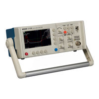
Mohr CT100B Series Operator's Manual (168 pages)
TDR Cable Analyzers
Brand:
Mohr
| Category:
Measuring Instruments
| Size: 3 MB
Table of Contents
Copyright Notice
3
Manual Updates
5
Warranty
7
Contacting MOHR
9
Table of Contents
11
Contents
12
List of Figures
15
General Information
19
Product Description
19
Power Requirements
19
Options and Accessories
19
Unpacking and Initial Inspection
20
Repacking for Shipment
20
Safety Summary
21
Terms in the Manual
21
Terms on the CT100B
21
Danger
21
Warning
21
Caution
21
Symbols in the Manual
22
Symbols on the CT100B
22
Static Charge
22
Fuses
23
AC Power Source
23
Grounding the CT100B
24
Danger Arising from Loss of Ground
24
Explosive Atmospheres
24
Do Not Remove Covers or Panels
25
Connecting Cables to the Test Port
25
Battery Replacement and Disposal
25
Getting Started
27
Handling
27
Powering the CT100B
27
Caring for the Battery
28
Charging and Power Status
28
Batteries and Long-Term Storage
28
Low Battery
28
Labels
29
Nameplate
29
Discharge Warning Label
29
License Codes
29
Example Nameplate Label Found on Back of a CT100B
29
Preparing to Use the CT100B
30
Front Panel Controls and Connectors
30
Diagram of the CT100B Front Panel
30
Rear Panel Connectors and Switches
31
Keyboard Alternate Controls
32
Diagram of the Rear Panel of the CT100B/CT100HF
32
Menu Selections and Function Buttons
33
M-FUNC Button
33
SCAN Button and Menu
33
Keyboard Controls for Front Panel Buttons and Knobs
33
SCAN Button and Menu
34
Math Menu
35
SELECT Button
37
AUTOFIT/HELP Button and Menu
37
CURSOR Button
38
FILE Button and Menu
38
The Reset Options Menu
38
Blue" MENU Button and Top-Level Menu
39
The Two Versions of the Main Menu
40
MENU Button and Menus
40
Setting up the CT100B
49
Navigating Dialog Boxes
49
Display Features
50
Setting Date and Time
51
Screenshot Showing Typical Features of the CT100B
51
Temperature Correction
52
Cable Length Settings
52
Sample Resolution
52
A Small Fault in a Long Cable
53
Measurement Settings
54
Horizontal Units
54
Vertical Units
54
Relative Reflection Coefficient (RRC) Method
55
Operating Instructions
57
Connecting to the Cable or Device-Under-Test (DUT)
57
Common Types of TDR Cable Faults
58
A Scan of an SMA Connector
59
Change Velocity of Propagation (Vp)
60
Fine Vp Control
60
Find an Unknown Velocity of Propagation (Vp)
60
Screenshot Showing AUTOFIT Result
61
Final Vp of the Cable
62
Cable Type Library
63
Load a Cable Type's Vp
63
Custom Cable Types
63
Smooth Settings
63
Distance-To-Fault
64
Measure Distance-To-Fault (DTF)
64
Smoothed Vs. Unsmoothed Traces at very Small Vertical Scales
64
AUTOFIT Cable. the Cable Termination Is a Short
65
Vertical Scale Used to Emphasize Cable Fault
65
Relative Distance and DTF Measurements
66
The Set/Clear Zero Offset Button on the Display Menu
68
The Zero Offset Menu
68
Multi-Segment Cable DTF Measurements
69
Multi-Segment Cable Segment with Vp of 0.400
70
Multi-Segment Cable Segment with Vp of 0.850
70
Scan a Cable
71
Working with Traces
72
Select a Trace
72
Scan Progress Display with Cancel Button
72
Selecting the Live Trace
73
Selecting a Scanned Trace
73
Annotate a Trace
74
Selecting a Difference Trace
74
The Annotations Selection in the Scan Menu
75
The Annotations Menu
75
Use Set Start Point to Annotate a Specific Point on a Trace
76
Use Set Start Point and Set End Point to Annotate a Range of Points on a Trace
76
Store a Trace
78
Using the On-Screen Keyboard
79
Load a Trace (Cable Records)
80
The Save Trace Default Dialog Box
80
Transfer and Delete Traces
81
Loading a Trace
81
User Configurations
82
Save Configurations
83
Load Configurations
83
Mask Testing
83
A Trace that Passes the Mask Test
84
A Trace that Fails the Mask Test
84
Storing a Mask
85
Loading a Mask
85
Saving and Loading a Mask as Part of a Configuration
85
Exporting/Importing a Mask
85
Deleting a Mask
86
Envelope Plot (Transient/Intermittent Fault Detection)
86
Envelope Plot with Fill Mode
87
Envelope Plot with Frequency Density Display
88
Improving Measurements
89
Vertical Reference (Vert. Ref.) Calibration
89
Cable Resistive Loss Correction
90
Take a Screenshot
91
Resistive Cable Loss Correction, before
91
Resistive Cable Loss Correction, after
91
Web Server
92
Remote Control
93
The Live Control Display on the CT100B Web Page
93
Math Functions
95
Difference (Subtraction) Traces
95
First Derivative (Slope) Traces
96
Difference Trace
96
Second and Higher Order Derivative Traces
97
Fast Fourier Transform (FFT) Traces
97
First Derivative Trace
97
Return Loss (S ) Traces
98
FFT Trace
98
Return Loss (S ) Options
99
Return Loss
100
Pre-Filter
100
Post-Filter
100
Phase Correction
100
Return Loss Plot
100
Cursors
101
Return Loss
102
Calibration Standards
102
Between Cursors with Tightened Connector
102
Between Cursors with Loosened Connector
102
Other Return Loss
103
Options
103
Improving S-Parameter Measurements
103
Normalized TDR Traces
104
Using a Phase Stable Cable to Improve S-Parameter Measurements
104
Layer-Peeling (Dynamic Deconvolution) Traces
105
Smith Charts
106
Example Layer-Peeling Trace
106
Smith Chart Representation of Open Fault
107
Smith Chart Representation of Short Fault
107
Smith Chart Representation of a 50 Ohm Resistive Load
108
Smith Chart of Reactive 200 Ohm Load
108
CT Viewer
109
Transferring Saved Traces to a Computer
109
Send Saved Traces with a Thumb Drive
109
Send Saved Traces over USB
110
Send Saved Traces Using Ethernet
110
Options under the Connect to CT Viewer Menu
111
Using Remote Control
112
Record and Playback Real-Time TDR Trace Movies
112
TDR Measurement Theory
113
Time-Domain Reflectometry (TDR)
113
Reflection Coefficients
113
Common Types of TDR Cable Faults
114
An Open Cable Fault Shows an Upward Step Edge at the Location of the Fault
114
A Short Cable Fault Shows a Downward Step Edge at the Location of the Fault
115
An Open Cable Fault at 824 Ft
115
Normal SMA Female Barrel Interconnect Measuring 52.1 Ohms
116
Velocity of Propagation (Vop, Vp)
117
Distance-To-Fault (DTF) and Cable Length
117
Impedance
117
Return Loss
119
Vswr
120
Rise Time and Spatial Resolution
121
Timebase/Cursor/Horizontal Resolution
122
Frequency-Domain Measurements
123
Scattering Parameters
123
Return Loss (S )
124
Insertion Loss (S )
124
Cable Loss (S )
124
Comparison of S
124
Normalized TDR Traces
125
Layer Peeling/Dynamic Deconvolution
125
Smith Charts
126
Specifications
129
Electrical Specifications
129
Environmental Specifications
131
Mechanical Specifications
131
Certifications and Compliances
131
Operator Performance Checks
133
General Information
133
Required Equipment
133
Required Performance Check Equipment for CT100B
133
Getting Ready
134
Operator Performance Checks
134
Options and Accessories
139
Options
139
Accessories
139
Standard BNC Accessories - CT100B (BNC)
139
Standard SMA Accessories
140
Optional Accessories
140
P of Common Cables
141
Cable Types
141
Dielectric Material
141
RG Standards
142
MIL-C-17 Standards
142
Commercial Designations
143
Twisted Pair
143
Maintenance and Service Instructions
145
Cleaning and Lubrication
145
Cleaning and Lubrication Interval
145
Battery Removal/Replacement
145
Calibration and Calibration Interval
146
Install CT100B License
146
Clean Storage
146
Operator Troubleshooting
147
General Information
147
Power on Test
147
Functional Block Diagram and Troubleshooting Flowcharts
147
Parts List
158
Glossary
159
Index
165
Advertisement
Advertisement
Related Products
Mohr CT100
Mohr CT100HF
Mohr Categories
Measuring Instruments
More Mohr Manuals
Login
Sign In
OR
Sign in with Facebook
Sign in with Google
Upload manual
Upload from disk
Upload from URL