Sign In
Upload
Manuals
Brands
Moeller Manuals
Control Panel
MV4-170-TA1
User Manuals: Moeller MV4-170-TA1 Touch Panel Interface
Manuals and User Guides for Moeller MV4-170-TA1 Touch Panel Interface. We have
1
Moeller MV4-170-TA1 Touch Panel Interface manual available for free PDF download: Hardware And Engineering
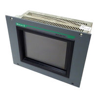
Moeller MV4-170-TA1 Hardware And Engineering (161 pages)
Display units and Operator Panels
Brand:
Moeller
| Category:
Control Panel
| Size: 1 MB
Table of Contents
Table of Contents
6
1 Explanation of Symbols
7
2 Introduction
8
3 Device Versions
8
Scope of Delivery
9
4 Device Mounting
10
General Mounting Instructions
10
Dimensions of the 10,4" Devices MV4-170-TA1(-Xx1), MV4-470-TA1(-Xx1)
13
Front Panel Cutouts for 10,4" Devices
14
5 Mounting Instructions
15
Mounting According to Degree of Protection IP 65
15
6 Connecting the System Power Supply
17
7 Connection to the Communication Interface
18
Preparing the Connection Cable (EMC)
18
Preparing the Shield Connections
19
8 Connection and Function of the Programming Port (PROG PORT)
20
9 Data Transfer (Download Button)
21
Loading the Runtime (GRSW)
21
Loading the Project Data (Download)
22
10 Communications Cards and COM SLOT
23
11 Expansion and Configuration Options
24
Additional 5 V Power Supply on Programming Port (PROG PORT)
24
12 Function and Control Leds
24
13 Touch Screen
25
Basic Touch Screen Function
25
Power up Function Test
25
Cleaning and Maintenance of the Touch Screen
25
14 Display
26
15 Maintenance and Repair
26
16 Disposal
26
17 Technical Data
27
18 EC Conformity
29
19 UL Listing
29
Table of Contents
32
1 Introduction
33
2 Device Version
33
3 Scope of Delivery
34
4 EC Conformity
35
5 Technical Data
35
6 Dimensions, Views, Front Plate Cutout
37
General Mounting Instructions
37
Dimensions 10.4"- Unit MV4-570-TA1/2(-Xx1)
38
Front Panel Cutouts for 10.4" Units
39
Dimensions for 13.8" Unit - MV4-590-TA1/2(-Xx1)
41
Front Cover Cutout for 13.8" Units
42
7 Connection Assignment
43
System Power Supply for AC Versions (100 to 240 V AC, TA2 Units)
43
System Power Supply for DC Versions (24 V DC, TA1-Units)
43
System Port (Function, Assignment)
44
8 Memory Card Slot
44
9 The Touch Screen
45
Basic Function of the Touch Screen
45
Power up Function Test
45
Cleaning and Care of the Touch Screen
45
10 Function and Control Leds
46
11 Communication Modules and System Expansion (Slot 0, Slot 1)
47
12 Installation Instructions
48
Device Installation
48
Mounting to IP 65
48
Preparation of the Connection Cables (EMC)
49
Preparing the Shield Connections
50
Table of Contents
53
1 Explanation of Symbols
54
2 Introduction
55
3 Device Versions / Type Designation
55
Scope of Delivery
56
4 Device Mounting
57
General Mounting Instructions
57
Dimensions for 10.4" Devices
58
Front Panel Cutouts for 10.4" Devices
59
Dimensions for 15" Devices
60
Front Panel Cutouts for 15" Devices
61
5 Mounting Instructions
62
Installation According to Degree of Protection IP65
62
6 Overview of the Connections and the Connector Panel
63
7 Connecting the System Power Supply
64
System Power Supply AC (100
64
DC System Power Supply, Isolated (24VDC) Type MV4-670/690-TA1(-Xx1)
65
8 Interface Connections and Cabling
66
Preparing the Connection Cable (EMC)
66
Preparing the Shield Connections
67
9 Connecting the Parallel Port
68
10 Connecting the Ethernet Interface
69
11 Connecting the System Port (Serial, RS232)
70
12 Download Button
70
13 Communication Cards and System Slot
71
14 Expansion and Configuration Options
72
System Interventions
72
Auxiliary Voltage Output on the System Port (5V)
72
15 Memory Card Slot
73
16 Function and Control Leds
74
17 Touch Screen
75
Basic Touch Screen Function
75
Power up Function Test
75
Cleaning and Maintenance of the Touch Screen
75
18 Display Technology, Backlight
76
19 Maintenance and Repair
76
20 Disposal
76
21 Technical Data
77
22 EC Conformity
79
Table of Contents
81
1 Introduction
83
Interface Connection ZB4-609-IF1
83
2 Configuration
84
Zb4-601-If1
84
Zb4-609-If1
85
3 Firmware
86
Zb4-601/609-If1
86
4 Preparing the Communication Cables
87
Communications Cable
87
Cable Lengths
87
Shield Connection
88
Simatic S7 - Mpi
88
5 Commissioning
89
6 Driver List ZB4-601/609-IF1
90
7 Driver Types
91
Bci 1.0
91
Driver Selection Errors
91
8 BCI 1.0 Drivers
92
Mitsubishi
92
Siemens
94
Siemens S7
96
Omron
100
Allen-Bradley
101
Matsushita
105
Texas Instruments
107
Elin Eldatic
108
Festo
109
AEG Modicon
110
Telemecanique
111
Honeywell
114
Jetter
115
Abb
117
Westinghouse
118
Mds
119
Data Transfer Protocol
120
Control Characters
120
Data Format
120
Troubleshooting
121
Send TP1 Procedure Command
121
Send TP2 Procedure Command
121
Notes
122
Receive TP1 Procedure Command
122
Receive TP2 Procedure Command
123
Special Note
123
Implementation Aids
123
Seitec
124
Selectron
125
9 BCI 2.0 Drivers
126
Siemens S7
126
Hapa
130
Moeller PS40
131
Table of Contents
136
1 Introduction
137
2 Indication Elements
137
3 Plug Connector Assignment
138
4 Preparation of PROFIBUS Cabling (Bus Cable)
138
PROFIBUS Topology
138
Bus Cables
139
Cable Lengths
139
Shield Connection/Potential Equalisation
139
Bus Connector
140
Line Termination
140
5 Firmware
141
6 Communication
142
Bci 2.0
142
Driver Selection Errors
142
GSD File
142
7 Layer 7 Profiles
143
8 Commissioning
147
Allen Bradley
148
Moeller PS416-NET-440
148
Iec 1131
148
9 Troubleshooting and Diagnostics Errors
149
Introduction
152
Connection
153
Control Display Leds
154
Configuration
154
Cable and Wiring Design
155
Cable Lengths
155
Line Termination
155
Shielding / Potential Equalization
156
Communication Cable Considerations (EMC)
156
Manufacturing a Shielded Connection
157
Application Layer
158
General Description
158
Prerequisites
158
Assembly Objects
158
Commissioning
158
HMI Profile Description
159
Appendix
160
EDS File Version 1.0
160
Notes
161
Advertisement
Advertisement
Related Products
Moeller MV4-150-TA1
Moeller MV4 Series
Moeller MV4-570-TA1
Moeller MV4-590-TA1
Moeller MV4-570-TA2
Moeller MV4-690-TA1
Moeller MV4-450-TA1
Moeller MV4-590-TA2
Moeller MV4-670-TA2
Moeller MV4-690-TA2
Moeller Categories
Industrial Electrical
Relays
Circuit breakers
Switch
Control Unit
More Moeller Manuals
Login
Sign In
OR
Sign in with Facebook
Sign in with Google
Upload manual
Upload from disk
Upload from URL