Sign In
Upload
Manuals
Brands
MMD Equipment Manuals
Portable Generator
SDG25S-6A7
MMD Equipment SDG25S-6A7 Generator Manuals
Manuals and User Guides for MMD Equipment SDG25S-6A7 Generator. We have
1
MMD Equipment SDG25S-6A7 Generator manual available for free PDF download: Service Manual
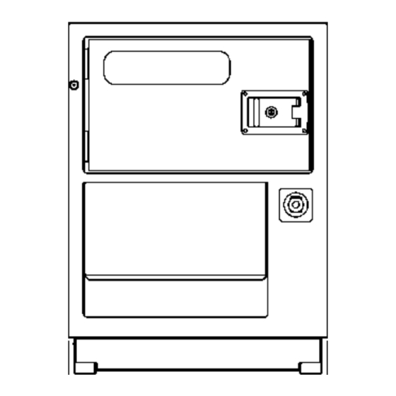
MMD Equipment SDG25S-6A7 Service Manual (110 pages)
Mobile Generators
Brand:
MMD Equipment
| Category:
Portable Generator
| Size: 1 MB
Table of Contents
Table of Contents
2
Specifications
3
Specifications
4
Outline Drawing
9
Sdg25S-6A7
9
Sdg45S-6A6
9
Sdg65S-6A6
10
Sdg100S-6A6
10
Sdg125S-6A6
11
Internal Components
12
Cautions for Overhauling
18
Precautions before Starting Work
18
Work to be Performed
18
Care Not to Spill Oil
18
Disassembly and Assembly
19
Tightening Torque
20
General Tightening Torque of Bolts and Nuts
20
Tightening Torque for Terminal Plate
21
Lifting Weight
22
Disassembly/Reassembly of Generator Main Unit and Connection of Generator Main Unit and Engine
22
Procedures of Disassembly
23
Demounting Stator and Rotor at the same Time from Engine
23
Measuring Center Deviation and Surface Deviation
24
Assembly of Engine Flywheel and Generator Coupling (Rotor)
25
Mounting Engine
25
Install Rotor
25
Size of Guide Bolt
25
Assembly of Flywheel Housing and Generator Main Unit Frame (Stator)
26
Install the Stator
26
S
26
Mounting of Generator Main Unit and Engine on Frame
27
Centering Method
28
Assembling Level Plates Size
28
Check the Gap between the Cooling Fan and Fan Shroud
29
Gap Size
29
Changing the Bearings in the Generator Main Unit
30
Replacement of Bearings
30
Changing the Rotary Rectifier
31
Replacement of Rotary Rectifier
31
Engine Maintenance Standards
32
Electrical Parts
35
Installation Positions of Electrical Appliances
35
Electrical Parts of Generator
36
Electrical Parts of Engine
37
Rotary Rectifier
40
AS (Ammeter Change-Over Switch)
41
Voltage Selector Switch
41
System of Contacts Arrangement
42
AVR (Automatic Voltage Regulator)
43
Avr Connector
43
Adjustment of AVR
44
Adjustment of Stability
44
Adjusting Time Constant
44
Protection against Excessive Exciting Current
44
Adjusting V/Hz Characteristic
45
Thermal Relay
46
Thermal Relay Set Value
46
Electric Parts of Engine
47
Alternator
47
List of Functions
48
Judgement of Alternator Functions
48
Controller
50
Emergency Indicator
55
Auto Start Unit (Automatic Operation Unit)
57
Glow Timer
62
Characteristics of Water Temperature and Glowing Time
63
Chart of Function
63
Cooling Water Temperature Sensor
63
Water Temperature and Resistance Characteristics
63
Water Temperature and Glow Time Characteristics
65
Cooling Water Sensor (for Automatic Pre-Heating)
65
Safety Relay
68
Starting Operation While Stopping
69
Starting Operation During Operation
69
Tachosensor
70
Checking Whether Voltage Generated between Terminals Is Proper or Not
70
Tachometer (with Hour Meter)
71
Stop Solenoid
72
Motor Stopper
73
Function of Motor Stopper
73
Before Engine Starts
73
Engine Starts
74
Rotation of Contact Plate
75
Stop of Contact Plate Rotation
75
Engine Stops (Normal Stop)
76
Emergency Stop
76
Fuel Gauge
77
Position of Meter Pointer
77
Sending Unit
78
SDG25S-6A7 (Equipped with Thermistor Sensor)
78
Position of Meter Pointer for Resistance Value
78
Specification of Thermistor
78
Diagram: Sending Unit for SDG100S to SDG150S
79
Electro-Magnetic Pump for Bleeding Air from Fuel Line
80
Type Without Filter
80
Type with Built-In Filter
80
Coolant Water Temperature Gauge
81
Temperature Range and Resistance Value of Sensor
81
Thermo-Sensor for Water Temperature Gauge
82
Characteristic of Temperature Resistance
82
Oil Pressure Gauge
83
Indicated Pressure and Standard Current Value
83
Oil Pressure Sensor for Oil Pressure Gauge
84
Standard Pressure and Standard Resistance Value
84
Engine Oil Pressure Switch
84
Engine Water Temperature Switch (for Emergency Stop)
84
Generator Wiring Diagram
85
Terminal Plate
87
Engine Wiring Diagram
90
Troubleshooting
95
Repairing Procedures
95
Safety Caution
95
Caution During Failure Diagnosis
95
How to Use the Failure Diagnosis
96
Generator Troubleshooting
97
No Voltage Is Generated or Voltage too Low
97
Voltage Is very High or It Cannot be Adjusted
98
Voltage Fluctuates
98
Load Cannot be Operated
99
Voltage Drops When Load Is Applied
99
Emergency Switch Functions
100
Engine Oil Pressure Drop Is Shown in Monitor and It Stops
100
Engine Troubleshooting
101
At Start-Up
101
It will Not Speed up to Rated Speed
102
Checking for Disconnection of Voltage Adjusting Resistor Hand Trimmer
103
Measurement of Generator Winding Wire Resistance
103
How ' " O Check
103
Generator Field Winding Wire
104
Exciter Armature Winding Wires
104
Exciter Field Winding Wire
104
Measurement of Insulation Resistance of Generator Winding Wires
105
Generator Armature Winding Wires
105
Voltage Selection Switch Position 480/277V
105
Checking Rotary Rectifier (Diode
107
Checking Varistor
107
Forced Excitation Method
108
Generated Voltage from Forced Excitation (at 480V)
108
References
108
Generator's Winding Wires Resistance Value [At ' " He Temperature of 68°F (20°C)]
108
Advertisement
Advertisement
Related Products
MMD Equipment SDG45S-6A6
MMD Equipment AirMan SDG125S-6A6
MMD Equipment SDG65S-6A6
MMD Equipment AirMan SDG150S-6A6
MMD Equipment SDG100S-6A6
MMD Equipment NGK-2900H
MMD Equipment NGK-4300H
MMD Equipment NGK-6000H
MMD Equipment NGK-7000H
MMD Equipment PowerPro IGR6000H
MMD Equipment Categories
Portable Generator
Air Compressor
Inverter
More MMD Equipment Manuals
Login
Sign In
OR
Sign in with Facebook
Sign in with Google
Upload manual
Upload from disk
Upload from URL