Sign In
Upload
Manuals
Brands
MJK Manuals
Controller
Connect
MJK Connect Pump Control RTU Manuals
Manuals and User Guides for MJK Connect Pump Control RTU. We have
1
MJK Connect Pump Control RTU manual available for free PDF download: Installation And User Manual
MJK Connect Installation And User Manual (304 pages)
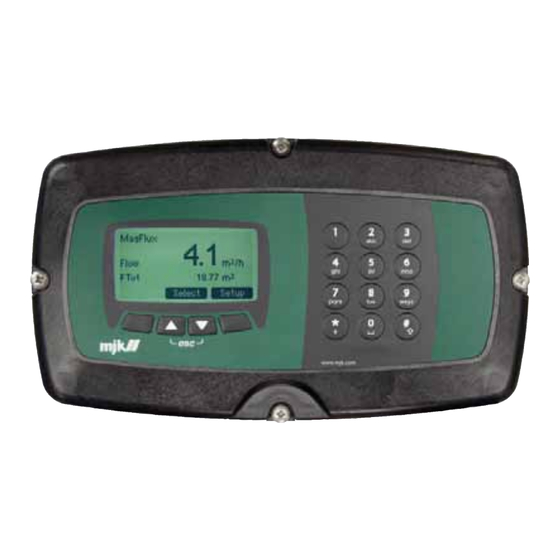
Controller and RTU Unit
Brand:
MJK
| Category:
Controller
| Size: 7 MB
Table of Contents
Table of Contents
3
1 Introduction
11
About this Manual
12
2 Safety, Repair and Product Identification
15
Safety Instructions
15
Physical Installation
15
Repair
15
Product Identification
15
3 Specifications
17
Table 1. Connect Display Specifications
17
Table 2. Connect Base Specifications
18
Table 3. Connect I/O Module 16-8-6-1 Specifications
18
Order Numbers
19
Table 4. Connect Communication Modules
19
Table 5. Connect Order Numbers
19
Table 6. Internal Connect Communication Modules (Modem)
20
Table 7. Connect Accessories
20
4 Power Supply and Signal Terminals
21
Figure 1. Front Panel Screws
21
Power Supply
22
Figure 2. Connection Terminals and Fuse Location
22
Table 8. Power Supply 12 VDC and 115 / 230 VAC
22
Table 9. Internal Fuses
22
Display Wires
23
Figure 3. Signal Terminals
23
Table 10. Display Wires
23
Digital Inputs
24
Table 11. Digital Inputs
24
Digital Outputs
25
Table 12. Digital Outputs
25
Analog Inputs
26
Analog Output
26
Table 13. Analog Inputs
26
Table 14. Analog Output
26
Serial Communication
27
Table 15. RS-485 Serial Communication
27
5 Configuration and Hook-Up Examples
29
Connection to Digital Inputs
30
Figure 4. Connection to Digital Inputs
30
Connection to Digital Outputs
32
Figure 5. Connection to Digital Outputs
32
Connection to Analog Inputs
34
Figure 6. Connection to Analog Inputs
34
Connection to a Passive, Analog Output
36
Figure 7. Connection to a Passive, Analog Output
36
Connection to an Active, Analog Output
37
Figure 8. Connection to an Active, Analog Output
37
Connect Unit with Modem, One Susix and One Magflux
38
Figure 9. Connect Unit with Modem, One Susix and One Magflux
38
Figure 10. Hook-Up for One Connect Unit with Modem, One Susix and One Magflux
39
Installation and Connection of a PSTN Modem
40
Figure 11. Installation and Connection of a PSTN Modem
40
Installation and Connection of a GSM/GPRS Modem
42
Figure 12. Installation and Connection of a GSM/GPRS Modem
42
Installation and Connection of an RS-232 Modem
44
Figure 13. Installation and Connection of an RS-232 Modem
44
Installation and Connection of Opto/Galvanic RS-232 Modem
46
Figure 14. Installation and Connection of Opto/Galvanic RS-232 Modem
46
6 Startup
49
Preliminary Checks
49
Language Selection
49
The Display - One Device Connected
50
Figure 15. Display and Keyboard for Reading and Programming
50
The Display - Multiple Devices Connected
51
Display Keys
52
Figure 16. Setting the Display Contrast
52
7 Connect Menus
53
Navigating the Menus
53
Factory Defined Main Menu
54
Setup
55
Connect Base 1 (Connect Configuration)
56
Main Functions
56
Connect Configuration / Individual Settings
57
Connect Configuration / Pump Control 1
57
Pump Control 1
58
Pumps Setup
58
Measurement
61
Start/Stop Levels
61
Additional Functions
62
Create Overview Screen
70
Optimized Raw Water Control
71
Pumps
71
Frequency Converter Type
72
Flow Input
73
Frequency States
75
Functions Menu
76
Adaptive Optimizing
78
Additional Functions
79
Create Overview Screen
83
Optimized Wastewater Control
84
Pumps Setup
84
Measurement
87
Frequency Converter Type
89
Flow Input
92
Level Parameters
94
Functions Menu
96
Adaptive Optimizing
98
Additional Functions
99
Create Overview Screen
107
Signals (I/O)
109
Analog Inputs
109
High Alarm
112
Low Alarm
113
Signal Name
114
Analog Outputs
115
Digital Inputs
118
Digital Outputs
120
Functions Menu
122
Interlock
122
Storm Flow Calculation
129
Logical Functions
132
Clock
135
Preset Counter
135
Reset Counter
135
Data Logger
137
Extended Data Logger
137
Standard Data Logger
137
Pump Control 2
142
Pumps Setup
142
Level
144
Start/Stop Levels
145
Create Overview Screen
146
Alarm Call
149
Call List
150
Call at Alarm off
152
Call at Voltage Drop
152
Automatic Alarm off
153
Call at Low Battery
153
Service Menu
154
Day Shift Time
155
Status
155
Password
156
Factory Settings
158
Unit Tag Name
158
Communication
159
Calibration
162
Product Data
162
Read/Write Reg
162
Technician Menu
162
Display
167
Language
167
Dansk, Svenska, Nederlands
167
GB English
167
Set Time/Date
168
Daylight Saving
168
Time Format
168
Factory Settings
169
Cancel
169
Delete Log
169
Restore Default Language
169
Restore Factory Settings
169
Display SW Version
169
Display Data Logger
170
Setup Overview Screen
170
Network (Modbus)
173
Add Device
173
Change Device Address
174
Remove Device
174
Change Display ID no
175
Set No. of Retries
175
8 Mechanical Dimensions
177
Figure 17. Mechanical Dimensions - Height X Width
177
Figure 18. Mechanical Dimensions - Depth
177
9 Maintenance
179
Service Agreement
179
Appendix A. Pop-Up and Error Messages
193
Appendix B. MJK-Field Link Software
195
Connect a PC to the Connect Base
196
Figure 19. Field Link Opening Menu
196
Figure 20. Mount USB
196
Figure 21. Synchronize Device Time
197
Figure 22. Link Status Display
197
Figure 23. Save Screen Configuration
197
Update Base Firmware
198
Figure 24. Firmware/Connect
198
Figure 25. Locate Base Firmware
198
Figure 26. Connect Flash Updating
198
Figure 27. Transferring Firmware
199
Figure 28. Programming Done
199
Connect a PC to the Connect Display Unit
200
Figure 29. Firmware Status
200
Save Log Data
201
Figure 30. Save Log to File
201
Figure 31. Save
201
Update Display Firmware
202
Figure 32. Firmware/Display
202
Figure 33. Locate Firmware
202
Figure 34. Confirm File Transfer
202
Figure 35. Field Link Status
203
Figure 36. Contrast Setting
204
Figure 37. File/Languages
204
Figure 38. Language Status
205
Figure 39. Select a Language Text File
205
Figure 40. Add Language/Language Pack
206
Figure 41. Update Status
206
Figure 42. Finishing the Update
207
Appendix C. Log Files
209
Figure 43. Example Log File
209
Figure 44. MJK Device Codes
210
Figure 45. MJK Device Type Codes
210
Figure 46. Graphical Display of Log File Data (in Excel)
211
Appendix D. MJK Instrument Link Software
213
Appendix E. Front Panel Cut-Out Template
215
Figure 47. Front Panel Cut-Out Template
215
Appendix F. Energy Optimization - an Example
217
Figure 48. Example of Energy Optimization
218
Principle for Energy Optimization
219
SCADA Parameters
220
Control Principle
221
Depth Pumping
221
Flush Function
221
Normal Operation
221
Hardware
222
Frequency Converter
222
Display
222
Automatic Optimization
222
Annex 1
223
Danfoss VLT Configuration
223
Electrical Connections of the Modbus Cable
223
Magflux
223
Menu Structures - Flow Charts
223
Wiring Diagram - Example
224
Appendix G. Two Interconnected Connect Units
227
Figure 49. Two Interconnected Connect Units
227
Appendix H. Changing the Supply Voltage
229
Figure 50. 230 VAC Single-Jumper Location
229
Figure 51. 115 VAC Dual-Jumper Location
230
Menu Structures
232
Connect Menu
232
Connect Menu - Continued 1
234
Connect Menu - Continued 2
235
Main Functions
238
Main Functions - Continued 1
239
Individual Settings
240
Pump Control 1
242
Additional Functions
244
Additional Functions - Continued 1
245
Pump Monitoring
246
Pump Monitoring - Continued 1
247
Pump Monitoring - Continued 2
248
Depth Pumping
250
Depth Pumping - Continued 1
251
Energy-Optimized Raw Water Control
252
Energy-Optimized Raw Water Control - Continued 1
253
Energy-Optimized Raw Water Control - Continued 2
254
Additional Functions - Raw Water
255
Energy-Optimized Wastewater Control
256
Energy-Optimized Wastewater Control - Continued 1
257
Energy-Optimized Wastewater Control - Continued 2
258
Additional Functions - Wastewater
259
Additional Functions - Wastewater - Continued 1
260
Create Overview Screen
261
Signals (I/O)
262
Interlock
268
Storm Flow Calculation
270
Storm Flow Calculation - Continued 1
271
Logical Functions
272
Logical Functions - Continued 1
273
Logical Functions - Continued 2
274
Data Logger
276
Data Logger - Continued 1
277
Data Logger - Continued 2
278
Pump Control 2
280
State Machine
282
Alarm Call
285
Servicemenu
286
Service Menu / Communication
286
Service Menu / Technician Menu
291
Display
292
Network (Modbus)
296
Advertisement
Advertisement
Related Products
MJK Categories
Transmitter
Power Tool
Measuring Instruments
Controller
More MJK Manuals
Login
Sign In
OR
Sign in with Facebook
Sign in with Google
Upload manual
Upload from disk
Upload from URL