
Summary of Contents for MJK Connect
- Page 1 Controller and RTU Unit Controller and RTU Unit Installation and User Manual Vol. I GB Connect Manual 091215 844003-002/841016-000/841516-000...
- Page 2 EN61000-6-3/-4:2001, EN61000-6-3/-4:2001, EN61000-6-1/-2:1999 EN61000-6-1/-2:1999 EN61000-6-3/-4:2001, EN61000-6-1/-2:1999 conformément aux dispositions conformemente alla disposizioni según las disposiciones de la(s) de Directive della Direzione directiva(s) 89/336/EEC; 92/31/EEC 89/336/EEC; 92/31/EEC 89/336/EEC; 92/31/EEC GB Connect Manual 091215...
-
Page 3: Table Of Contents
Connect Unit with Modem, one SuSix and one MagFlux . . . . . . . . . . . . . . . . - Page 4 Setup ............55 Connect Base 1 (Connect configuration) ......56 Main Functions* .
- Page 5 Controller and RTU Unit Logical Functions . . . . . . . . . . . . . . . . . . . . . . . . . . . . . . . . . . . . . . . . . . . . . . . 132 Preset counter .
- Page 6 Service Agreement . . . . . . . . . . . . . . . . . . . . . . . . . . . . . . . . . . . . . . . . . . . . . . 177 Index IDX1-1 GB Connect Manual 091215...
- Page 7 C . Connect a PC to the Connect display unit . . . . . . . . . . . . . . .
- Page 8 Connect Menu - continued 1 ........
- Page 9 Figure 26. Connect Flash Updating ........
- Page 10 Figure 49. Two Interconnected Connect Units ....... . . 213...
-
Page 11: Introduction
Bluetooth , serial communication protocols, ® network topologies, repeaters, etc. You can always contact your local representative or the MJK hot lines for advice and guidance: • Europe Tel.: +45 45 56 06 56 E-mail: mjk@mjk.com •... -
Page 12: About This Manual
Volume I 1. Introduction Contains a presentation of the MJK Connect Controller and RTU Unit, the structure of this manual and the operating principles. 2. Safety, Repair and Product Identification Provide answers to issues regarding safety, mounting, repair, restric- tions and product identification. - Page 13 Example log file illustrating the format and explaining the content. Appendix D. Connect Link Software A short user guide for the Connect Link software programme which can be used for downloading, changing, saving and uploading different Connect configurations to and fro a Windows-configured PC.
- Page 14 Controller and RTU Unit This page is intentionally left blank. GB Connect Manual 091215...
-
Page 15: Safety, Repair And Product Identification
• WARNING: There is a risk of electric shocks from the mains terminals N and L. Avoid touching these while the Connect is being serviced or repaired. • WARNING: Incorrect or incomplete installation or use can lead to... - Page 16 Controller and RTU Unit This page is intentionally left blank. GB Connect Manual 091215...
-
Page 17: Specifications
Real-time clock with integrated lithium battery (10 years Clock life expectancy) Communication RS-485 Modbus RTU-mode for communication ® between one to four Connect units Interface 1 RS-485 Interface 2 USB 1,1 type mini B, female Interface 3 Communications module 32 Mb Flash-memory, 168.000 loggings including date,... -
Page 18: Table 2. Connect Base Specifications
Clock life expectancy) Memory 32 Mb Flash-memory, 200.000 loggings depending on chosen protocol Interface 1 pc. RS-485 galvanic separation for 1-4 pcs. Connect 1 pc. RS-485 galvanic separation for 1-4 pcs. MagFlux ® SuSix , Oxix, etc. ® 1 pc. communication module for security installations and other Connect units. -
Page 19: Order Numbers
Connect base with display I/O module 16-8-6-1 205322 Connect base with display I/O module 12-4-2-2 205341 Connect base with display and PSTN I/O module 16-8-6-1 205342 Connect base with display and GSM I/O module 16-8-6-1 205343 Connect base with display and GPRS... -
Page 20: Table 6. Internal Connect Communication Modules (Modem)
Connect PSTN modem 205542 Connect GSM modem dual-band 205543 Connect GPRS modem dual-band 205544 Connect RS-232 opto, galvanically isolated RS-232 205545 Connect RS-485 opto, galvanically isolated RS-485 with repeater 205546 Connect RS-485 MODBUS ® 205547 Connect RS-485 PROFIBUS ® 205548... -
Page 21: Power Supply And Signal Terminals
Controller and RTU Unit 4. Power Supply and Signal Terminals WARNING! The Connect Controller and RTU Unit may not be installed in environments with danger of explosion! Caution! The Connect unit may not be connected to the main supply before all signal wires and power cords have been connected and secured. Loosen the 4 screws shown with arrows and remove the display to gain access to the signal and power connection terminals. Figure 1. Front Panel Screws 4. -
Page 22: Power Supply
Controller and RTU Unit Power Supply Connect must be supplied from a voltage supply group with a stable voltage (see “B”, Figure 2) or from a 12 VDC constant-voltage power supply/battery (see ”A”, Figure 2). The internal fuse is located at “C”. -
Page 23: Display Wires
Name/function + 15 V White RS-485 A Grey RS-485 B Black Table 10. Display wires NB: The same signals/voltages are also available from the “Connect net” terminals. Signal Terminals Figure 3. Signal Terminals 4. Power Supply and Signal Terminals 844003-002/841016-000/841516-000... -
Page 24: Digital Inputs
Controller and RTU Unit Digital Inputs Connect is equipped with 16 digital, passive inputs which can be activated by a voltage higher than 10 VDC and deactivated by a voltage lower than 5 VDC (see position “H” on page with an I/O Module 16-8-6-1 installed). -
Page 25: Digital Outputs
Controller and RTU Unit Digital Outputs Connect is equipped with 8 digital outputs (DO1 - DO8) with electronic potential-free relays (see position “G” on page with an MJK I/O Module 16-8-6-1 installed). The outputs can be individually configured to NO (normally open) or NC (normally closed). -
Page 26: Analog Inputs
+15 VDC (pull-up for passive signals) AO1+ 4 - 20 mA, +15 VDC AO1- Ground for AO1+ GND AO Ground for 15 V AO Table 14. Analog Output The analog output can be programmed to indicate primary units. GB Connect Manual 091215... -
Page 27: Serial Communication
Controller and RTU Unit Serial Communication See position ”D” on page 23. Use Connect serial communication to link to other devices such as MJK MagFlux and SuSix (see page 32) RS-485 Serial Communication Terminal Designation/Function MJK network RS 485-1, 15V... - Page 28 Controller and RTU Unit This page is intentionally left blank. GB Connect Manual 091215...
-
Page 29: Configuration And Hook-Up Examples
® ® solids transmitter and other MJK Connect units. The Connect display unit can be used as a common display for these products. This section shows a few configuration examples including cable connec- tions, order numbers and typical connection examples: •... -
Page 30: Connection To Digital Inputs
NO contact terminal ”1” 2. Connect terminal ”DI 1” is connected to: NO contact terminal ”2” 3. Connect terminals ”GND EXT” and ”(-) COM DI 1-8”. Connection of an NC contact: 1. Connect terminal ”15V EXT” is connected to: NC contact terminal ”1”... - Page 31 Controller and RTU Unit The digital inputs are passive, which causes the voltage to be supplied from an external voltage source or from terminal “15V EXT. Important! A commonly occurring installation error is inputs not connected to the correct, common minus terminal ! Note that inputs share minus in groups of 8 inputs, and that inputs can be individually configured to be normally open (NO) or normally closed (NC).
-
Page 32: Connection To Digital Outputs
(-) COM GND EXT GND AO DI 9-16 24 VAC Power Supply Figure 5. Connection to Digital Outputs The example above shows connection of an external transfer relay (max. 120 mA), internally or externally voltage supplied. GB Connect Manual 091215... - Page 33 Controller and RTU Unit Connection of external transfer relay - internally voltage- supplied 1. Connect terminal ”15V EXT” is connected to: transfer relay coil terminal ”+” 2. Connect terminal ”DO 1+” is connected to: transfer relay coil terminal ”-” 3. Connect terminals ”DO 1-” and ”GND EXT”.
-
Page 34: Connection To Analog Inputs
AO1+ DO 8- DI 16 AO1- (-) COM GND EXT GND AO DI 9-16 Shuttle Connection of an active mA transmitter signal Expert Connection of a passive mA transmitter signal Figure 6. Connection to Analog Inputs GB Connect Manual 091215... - Page 35 (here: Expert) with a passive output connected to the analog input 2 (AI2). ”Passive” connection: 1. Connect terminal ”15V AI” is connected to: Expert cable ”1” (red cable, +) 2. Connect terminal ”AI2+” is connected to: Expert cable ”2” (brown conductor, return) 3.
-
Page 36: Connection To A Passive, Analog Output
The example above shows the connection of an external control unit, a PLC or similar with an active, analog input. ”Active” connection: 1. Connect terminal ”AO1+” is connected to: PLC terminal ”+24 VDC” 2. Connect terminal ”AO1-” is connected to: PLC terminal ”+mA”... -
Page 37: Connection To An Active, Analog Output
”Passive” connection: 1. Connect terminal ”AO1-” is connected to: PLC terminal ”+mA” 2. Connect terminal ”GND AO” is connected to: PLC terminal ”GND” 3. Connect terminals ”15V AO” and ”AO1+”. The analog output (AO1) is passive. For an active output, the internal volt- age supply from terminals “AO 15V and GND AO”... -
Page 38: Connect Unit With Modem, One Susix And One Magflux
Figure 9. Connect Unit with Modem, one SuSix and one MagFlux Order Numbers Order numbers for this configuration: • 1 pcs. 20534x Connect base, with display, with I/O module, with modem communication module of own choice • 1 pc. 2063xx SuSix converter with or without display •... -
Page 39: Figure 10. Hook-Up For One Connect Unit With Modem, One Susix And One Magflux
DO 8+ DI 15 AO1+ DO 8- DI 16 AO1- (-) COM GND EXT GND AO DI 9-16 SuSix MagFlux Figure 10. Hook-up for one Connect Unit with Modem, one SuSix and one MagFlux 5. Configuration and Hook-up Examples 844003-002/841016-000/841516-000... -
Page 40: Installation And Connection Of A Pstn Modem
Controller and RTU Unit Installation and Connection of a PSTN Modem • ☎ Figure 11. Installation and Connection of a PSTN Modem The example above shows the installation and connection of a PSTN Con- nect modem GB Connect Manual 091215... - Page 41 3. Mount the PSTN modem in the internal S4 interface for communication units and attach it with the supplied screws (4 pcs. M3x6). 4. Connect the PSTN modem with the supplied RJ11 cable. If the mo- dem is to be connected to a terminal, the cable must be stripped at one end, and the red and blue conductor connected to the terminal block.
-
Page 42: Installation And Connection Of A Gsm/Gprs Modem
Installation and Connection of a GSM/GPRS Modem Figure 12. Installation and Connection of a GSM/GPRS modem The example above shows the installation and connection of a Connect GSM/GPRS modem, plus connection of an MJK GSM or GPRS antenna: 205116/18 or 205120. - Page 43 3. Mount GSM / GPRS modem (including SIM card) in the internal inter- face S4 for communication units and secure with the supplied screws (4 pcs. M3x6). 4. Connect GSM / GPRS modem to the desired type of antenna using a cable with MMCX male connector. 5. Reinstall Connect I/O module.
-
Page 44: Installation And Connection Of An Rs-232 Modem
Controller and RTU Unit Installation and Connection of an RS-232 Modem Figure 13. Installation and Connection of an RS-232 Modem GB Connect Manual 091215... - Page 45 3. Mount the RS-232 modem in the internal S4 interface for communica- tion units and attach it with the supplied screws (4 pcs. M3x6). 4. Connect the RS-232 modem to the MJK 795 Data Transmitter with a 2-wire,insulated cable: Connect terminal “TxD” to 795 terminal “RS232 / A”...
-
Page 46: Installation And Connection Of Opto/Galvanic Rs-232 Modem
Controller and RTU Unit Installation and Connection of Opto/Galvanic RS-232 Modem Data radio blue-brown- black black-red black-red Figure 14. Installation and Connection of Opto/Galvanic RS-232 Modem GB Connect Manual 091215... - Page 47 3. Mount the RS-232 modem in the internal S4 interface for communica- tion devices and attach it with the supplied screws (4 pcs. M3x6). 4. Connect the RS-232 modem to the TP6000 data radio with the MJK 3-wire, DB25 cable: Connect terminal “TxD”...
- Page 48 Controller and RTU Unit This page is intentionally left blank. GB Connect Manual 091215...
-
Page 49: Startup
Controller and RTU Unit 6. Startup Preliminary Checks The following steps must be checked, before power is connected for the first time: • The local mains supply voltage corresponds to the voltage printed on the unit’s ID label. • All electrical connections are made in accordance with the described electrical connections starting on page 21. -
Page 50: The Display - One Device Connected
A 5-line LCD display shows the symbols and numbers of the current status. See below an example of a screen display for a Connect connected to a MJK SuSix turbidity and suspended solids transmitter unit without a local display. -
Page 51: The Display - Multiple Devices Connected
Controller and RTU Unit The Display - Multiple Devices Connected When several MJK devices are connected to the same network, for ex- ample one MagFlux flow meter, one Oxix dissolved oxygen transmitter ® ® and one SuSix turbidity and suspended solids transmitter, measurements ®... -
Page 52: Display Keys
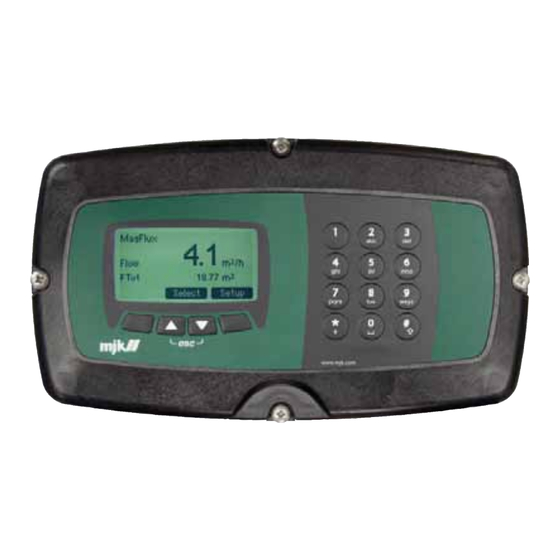
Numeric keys and soft keys (soft keys: the function is determined by the installed display firmware) are used for start-up and normal operation of the Connect unit. The function of the 4 soft keys is shown at the bottom of the display (here: Select and Setup). The numeric keypad on the right is used for direct menu selection and alpha-numeric entry of names and texts. -
Page 53: Connect Menus
Example: Pumps setup Pumps setup Level Start/stop levels ( Menu / Connect 1 / Functions Menu / Pump Control 2 / Pumps setup ) Create Overview Screen Back Select Pump Control 2 Pump Control 2... -
Page 54: Factory Defined Main Menu
However, notice that all these configurations can be changed and modi- fied to meet specific demands. Back Select 1. Press “Back” on the Connect display until the following screen is ob- tained (the names of the 8 menus may vary): Setup overview screen Main Function 1... -
Page 55: Setup
Connect Configuration Main Function* Signals (I/O) Functions Menu • Connect Base 1 which allows configuration of the parameters for Alarm Call pump control, definition of signals, functions, services and alarms just Service Menu to mention a few examples. These tools/menus will be shown and described on the following pages beginning on page 56. -
Page 56: Connect Base 1 (Connect Configuration)
Digitale outputs Back Select Back Select Through “Main Functions” the basic functionalities of Connect can be selected either by: an individual or a guided setup of pump manage- ment. See: 1.2 – Signals (I/O See: 1.1 – Main Functions Note: This menu is only visible as long as there has been made no selection between “Individual settings”... -
Page 57: Connect Configuration / Individual Settings
Connect Configuration / Pump Control 1 Individual settings Pump Control 1 Optm. raw water control ( Setup / Connect configuration / Main functions* / Pump Control 1 ) Connect configuration Pump Control 1 Optm. raw water control nals (I/O) -
Page 58: Pump Control 1
Pump Control 1 Pumps setup Pumps setup Pumps setup ( Setup / Connect configuration / Main functions* / Pump Control 1 / Pumps setup ) Measurement Setup pump no Measurement From “Pumps setup” you can choose constant or time based opera-... - Page 59 Back Select Pump Control 1 Back Select Back Select Pumps setup Back Select No of simultan Pump Control 1 working pumps Pumps setup No of simultan Back Select working pumps 7. Connect Menus 844003-002/841016-000/841516-000 Back Select...
- Page 60 Pumps setup Pumps setup No of simultan No of simultan working pumps working pumps Back Select Back Select 1.2 - Pump Control 1 - GB Connect menus 1.2 - Pump Control 1 - GB Connect menus GB Connect Manual 091215...
-
Page 61: Measurement
1.2.1 – Signaler Start/Stop levels Pump Control 1 ( Setup / Connect configuration / Main functions* / Pump Control 1 / Start/stop levels ) Setup pump no # From “Start/stop levels” the start and stop levels for each pump can be ital output defined separately. -
Page 62: Additional Functions
Stop level Se: 1.1.2.4 - Additional Pump monitoring Additional functions Functions Additional functions ( Setup / Connect configuration / Main functions* / Pump control 1 / Additional functions / Pump Back Select Pump monitoring monitoring ) Pump monitoring Setpoint displacement Setpoint displacement From “Pump Monitoring”... - Page 63 Back Select Back Back Back Back Select Pump monitoring, pump # Pump m 7. Connect Menus 844003-002/841016-000/841516-000 Pump monitoring, pump # Pump m Pump monitoring, pump # Pump m Alarm signal number Pump monitoring, pump # Alarm signal number Alarm signal number...
- Page 64 Digital input AI Low alarm 0000 Sec Int. Flag Back Select Back Back Select Pump monitoring, pump # Pump m Alarm signal number Digital input AI Low ala 1-16 6/28 29. janua ct menus Back Back GB Connect Manual 091215...
- Page 65 Controller and RTU Unit Setpoint displacement ( Setup / Connect configuration / Main functions* / Pump Control 1 / Additional functions / Setpoint displacement ) Setpoint displacement is important in SCADA installations for shifting min. and max. values up or down, and for using the sewerage system as a buffer at heavy rainfall or by day/night control.
- Page 66 Not in use Controller and RTU Unit Back Select Setpoint displacement Start time 0.00.00 h:m:s Stop time 0.00.00 h:m:s Back Select s - GB Connect menus GB Connect Manual 091215...
- Page 67 Pump Control 1 Controller and RTU Unit Depth pumping ( Setup / Connect configuration / Main functions* / Pump Control 1 / Additional functions / Additional Functions Depth pumping ) Pump monitoring From ”Depth pumping” you can decide whether a pump well should be...
- Page 68 ### hours In use Not in use Not in use Back Select Back Select Back Select Back Select Back Select ↓ Depth pumping Depth pumping Time of day Time of day xx.xx xx.xx Back Select Back Select GB Connect Manual 091215...
- Page 69 Controller and RTU Unit Flow calculation ( Setup / Connect configuration / Main functions* / Pump Control 1 / Additional functions / Flow calculation ) “Flow calculation” makes it possible to calculate the flow from the mea- sured changes in level including taking into account the influx during pumping.
-
Page 70: Create Overview Screen
Select < Select < Select Create Overview Screen ( Setup / Connect configuration / Main functions* / Pump control 1 / Create Overview Screen ) Pump Control 1 Pump Control 1 Additional Functions Create Overview Screen Pump monitoring Setpoint displacement... -
Page 71: Optimized Raw Water Control
Pumps Optm. raw water control mps setup ( Menu / Connect Base 1 / Main Functions / Optimized raw water cotrol / Pumps ) quency converter type w input ”Signal name” should be a meaningful and descriptive name for the quency states concerned pump control. -
Page 72: Frequency Converter Type
Controller and RTU Unit Frequency Converter Type ( Menu / Connect Base 1 / Main Functions / Optm. raw water control / Frequency converter type ) ”VLT FC202” refers to the driver for the Danfoss’ VLT FC 202 frequency converter. “Others” refers to a generic driver for frequency converters which are not made by Danfoss. -
Page 73: Flow Input
Flow input ( Menu / Connect Base 1 / Main Functions / Optm. raw water control / Flow input ) ”MJK” indicates that a MJK MagFlux converter has been connected to the Connect. “Others” refers to a generic driver for non-MJK flow meters. - Page 74 Optm. raw water control Back Select Back Select Frekvens states 8 Frequency 0 Hz Optm. raw water control Optm. raw water control < Select Flow input Frequency converter type Alarm name Alarm name < Select < Select GB Connect Manual 091215...
-
Page 75: Frequency States
Controller and RTU Unit Frequency states ( Menu / Connect Base 1 / Main Functions / Optm. raw water control / Frequency states ) It is possible to run the raw water pumps in up to 8 fixed states, where each state corresponds to a certain frequency. -
Page 76: Functions Menu
Controller and RTU Unit Functions Menu ( Menu / Connect Base 1 / Main Functions / Optm. raw water control / Functions Menu ) “Functions Menu” defines within which limits the pump should operate. Optm. raw water control Optm. raw water control Optm. - Page 77 0.00 m3/h < Select “Start-up time” indicates the time between the Connect receives a start signal until it has reached 50 Hz (ramp time) “Preferred frequency” is a reference frequency. When the pump starts, it accelerates to the “Preferred frequency”-frequency and regulates itself until it reaches the lowest possible energy consumption within the set limits.
-
Page 78: Adaptive Optimizing
Controller and RTU Unit Adaptive optimizing ( Menu / Connect Base 1 / Main Functions / Optm. raw water control / Adaptive optimizing ) “Adaptive optimizing” makes the Connect capable of calculating the optimal operating condition possible based on the highest possible volume per kWh. -
Page 79: Additional Functions
Controller and RTU Unit Additional Functions ( Menu / Connect Base 1 / Main Functions / Optm. raw water control / Additional Functions ) “Additional Functions” for optimized raw water control makes it pos- sible to output a variety of informations in an easy way. - Page 80 Delay Alarm signal type 0 sec Not in use Back Select > Digital input Digital output AI High alarm AI Low alarm Logical Function Back Select > Pump monitoring, pumpe 1 GB Connect Manual 091215 Alarm signal number Digital input...
- Page 81 Functions - GB Connect menus “Delay” indicates the delay from the time the input is activated until the signal is received by the Connect. The purpose of this function is to prevent influence from fluctuations. “Alarm signal” defines the number of alarms that should be registered from pump 1.
- Page 82 Controller and RTU Unit Control signal ( MMenu / Connect Base 1 / Main Functions / Optm. raw water control / Additional Functions / Control signal ) “O-MAN-AUT” in use provides feedback to the Connect about the operating condition (on or off) and about manual or automatic control.
-
Page 83: Create Overview Screen
“Start stop signal” indicates the digital outputs that can force a pump to a halt. Create Overview Screen ( Menu / Connect Base 1 / Main Functions / Optm. raw water control / Additional functions / Create Overview Screen “Create overview screen” automatically generates a standard overview screen for the display. -
Page 84: Optimized Wastewater Control
Pumps setup umps setup Setup pump no Pumps setup easurement equency converter type ( Menu / Connect Base 1 / Main Functions / Optm. wastewater control / Pumps setup ) ow input Back evel parameters Optm. wastewater control Optm. wastewater control daptive optimizing Niveaumåling... - Page 85 It should not be set higher than pump’s labelled fre- Signal Name quency to prevent damage to the electric motor. xxxxx Select Back ptm. wastewater control requency converter type 7. Connect Menus 844003-002/841016-000/841516-000 mp down gister no.
- Page 86 < Select “Signal name” should be an descriptive name for the chosen pump. This name will also be shown on the display. 1.4 - Optm. waste water control - GB Connect menus GB Connect Manual 091215...
-
Page 87: Measurement
Controller and RTU Unit Measurement ( Menu / Connect Base 1 / Main Functions / Optm. wastewater control / Pumps setup ) Under “Analog inputs” the individual analog 4-20 mA inputs can be configured. The individual inputs can be selected with the arrow keys. - Page 88 Optm. wastewater control Optm. wastewater control Pumpe 1 Frequency converter type Signal Name Current xxxxx Register no. Back < Select Optm. wastewater control Frequency converter type Start stop signal Register no. < Select control - GB Connect menus GB Connect Manual 091215...
-
Page 89: Frequency Converter Type
Controller and RTU Unit Frequency converter type ( Menu / Connect Base 1 / Main Functions / Optm. wastewater control / Frequency converter type ) ”VLT FC202” refers to the driver for the Danfoss’ VLT FC 202 frequency converter. “Others” refers to a generic driver for frequency converters which are not made by Danfoss. - Page 90 Optm. wastewater control Frequency converter type Flow input Current Signal name Register no. Present flow < Select Back Select Optm. wastewater control Analog inputs AI 1 – AI 1 Frequency converter type GB Connect Manual 091215 Start stop signal Register no.
- Page 91 Optm. wastewater control Ramp up Pumpe 1 Register nr. Signal Name xxxxx < Select Back Optm. wastewater control Frequency converter type Ramp down Register no. < Select 7. Connect Menus 844003-002/841016-000/841516-000 1.1.4 - Optm. waste water control - GB Connect m...
-
Page 92: Flow Input
Controller and RTU Unit Flow input ( Menu / Connect Base 1 / Hovedfunktioner* / Energioptimeret spildevandspumpestyring / Flow indgang ) “MJK” indicates that an MJK MagFlux flow meter is connected to the Connect unit. “Others” refers to a generic driver for non-MJK flow me- ters and is described under “Measurement”... - Page 93 Signal name Register no. Present flow < Select Back Select Analog inputs Optm. wastewater control AI 1 – AI 1 Frequency converter type Start stop signal Register no. AI 6 – AI 6 < Select Back Select 7. Connect Menus 844003-002/841016-000/841516-000...
-
Page 94: Level Parameters
Controller and RTU Unit Level parameters ( Menu / Connect Base 1 / Main Functions / Optm. wastewater control / Level parameters ) At “Max level” all pumps start at max. frequency (typically 50 Hz). At “Start level” all pumps run at max. frequency for x seconds, after which the frequency is lowered to the reference frequency. - Page 95 Pumped volume < Select Back Select Optm. wastewater control Optm. wastewater control Flow Flow input Signal name 0.00 m3/h Present flow < Select Back Select Analog inputs AI 1 – AI 1 7. Connect Menus 844003-002/841016-000/841516-000 AI 6 – AI 6...
-
Page 96: Functions Menu
Controller and RTU Unit Functions Menu ( Menu / Connect Base 1 / Main Functions / Optm. wastewater control / Functions Menu ) “Wash out/Start time” indicates when the frequency of the pump in- creases to max. frequency in order wash out the pipes. - Page 97 > Optm. wastewater control “Startup time” shows the number of seconds from the time when the Level parameters Connect gets its start signal until it reaches 50 Hz (ramp time). Is en- Prefered level Optm. wastewater control tered in seconds.
-
Page 98: Adaptive Optimizing
Controller and RTU Unit Adaptive optimizing ( Menu / Connect Base 1 / Main Functions / Optm. wastewater control / Adaptive optimizing ) “Adaptive optimizing/In use” enables calculation of the optimal operat- ing point. It is calculated from to highest obtainable volume per kWh. If necessary, the frequency is automatically re-adjusted. -
Page 99: Additional Functions
Controller and RTU Unit Additional functions ( Menu / Connect Base 1 / Main Functions / Optm. wastewater control / Additional functions ) Additional functions for optimized wastewater pumping provides several useful options for the current control. Optm. wastewater control Optm. - Page 100 Controller and RTU Unit Pump monitoring ( Menu / Connect Base 1 / Hovedfunktioner* / Energioptimeret spildevandspumpestyring / Tillægsfunktioner / Pumpeovervågning ) “Pump monitoring/In use” activates the pump monitoring functions. In ewater control “Setup pump no” the required pump is selected.
- Page 101 “Delay” indicates the delay from the time that the input is activated until the signal enters the Connect. The purpose of this function is to prevent fluctuations. Alarm signal (see figure, next page, right half) “Alarm signal/Count”...
- Page 102 AI høj alarm Delay AI lav alarm 0 sec Logical funktioner Back Select > Back Select > Pump monitoring, pump # Alarm signal nr. Digital input Back Select > GB Connect Manual 091215 ewater Additional Functions - GB Connect menus...
- Page 103 Controller and RTU Unit Depth pumping ( Menu / Connect Base 1 / Main Functions / Optm. wastewater control / Additional functions / Depth pumping ) Depth pumping is a function that pumps to a lower level than the nor- mal stop value.
- Page 104 “Duty periods between” is the number of start/stops between which depth pumping is running. “Hours between” is the number of hours between which depth pump- ing is running. “Time of day” indicates the time where depth pumping is running. GB Connect Manual 091215...
- Page 105 Controller and RTU Unit Control signal ( Menu / Connect Base 1 / Main Functions / Optm. wastewater control / Additional functions / Control signal ) “Pump monitoring/Setup pump no” indicates which pump to monitor. “O-MAN-AUT” in use enables reporting to the Connect whether the operation condition is set to off, there is a manual control, or there is automatic control of for example pump 1.
- Page 106 Time of day < Select < Select Pump monitoring, pump # Start stop signal DO 1 DO 2 DO 8 Instrument network < Select Optm. wastewater control Pump monitoring, pumpe 1 Reference frekvensudgang AO 1 < Select GB Connect Manual 091215...
-
Page 107: Create Overview Screen
Controller and RTU Unit Additional functions Create Overview Screen ( Menu / Connect Base 1 / Main Functions / Optm. wastewater control / Additional functions / ter control Create Overview Screen “Create overview screen” automatically generates a preconfigured 0.00 m3/h overview screen for the display. - Page 108 Frequency Back Select Setup Back Select Controller and RTU Unit Optm. wastewater control Control pumps Back Optm. wastewater control Control pumps Stop Pump monitoring Forced stop to start level Forced start to stop level Cancel Back GB Connect Manual 091215...
-
Page 109: Signals (I/O)
AI 7 - Signal name AI 8 - Signal name Analog inputs Back Select Signals (I/O) Signals (I/O) ( Setup / Connect 1 / Signals (I/O) / Analog inputs ) Analog inputs Analog inputs Analog outputs Analog outputs Signals (I/O) Digital inputs... - Page 110 Each of the individual units may subsequently be configured according High 300 cm to the 4- and 20 mA settings, limitations, alarm thresholds (high and low alarm) and the signal name. < Select Analog input # GB Connect Manual 091215 Average 0-60 sec...
- Page 111 Analog input # Analog input # High alarm Set Point limitation Signal name 00 cm Back Select < Select Analog input # Set Point Limitation High 300 cm < Select Analog input # Average 0-60 sec < Select 7. Connect Menus 844003-002/841016-000/841516-000...
-
Page 112: High Alarm
Analog input # Analog input # Analog input # High alarm Low alarm Set Point limitation Signal name Signal name 00 cm Back Select Back Select < Select Analog input # Set Point Limitation GB Connect Manual 091215 High 300 cm... -
Page 113: Low Alarm
Analog input # High alarm Low alarm Alarm call Alarm call In use in use Not in use Select Back Select Analog input # Analog input # High alarm Low alarm nal name Signal name Select Back Select 7. Connect Menus 844003-002/841016-000/841516-000... -
Page 114: Signal Name
Back Select < Select Analog input # Analog output # Low alarm 2. Set Point (low) Signal name Back Select < Select Analog output # 1. Set Point (high) < Select GB Connect Manual 091215 Analog output # Ramp time... -
Page 115: Analog Outputs
Analog outputs Analog inputs 1 - Signal name ( Setup / Connect 1 / Signals / Analog outputs ) 2 - Signal name From “Analog outputs” it is possible to select a scaling of primary units, 3 - Signal name... - Page 116 Analog output # Unit Analog input # Signal Name Back Select Back Select Analog output # 4 mA scale 000000 mA Back Select Analog output # 20 mA scale 000000 mA Back Select GB Connect Manual 091215 Analog output # Decimal Point...
- Page 117 2. Set Point (low) 00 cm < Select Analog output # 1. Set Point (high) 300 cm < Select Analog output # Ramp time 0-999 sec Back Select Analog output # Signal Name Back Select 11/28 29. janu 7. Connect Menus 844003-002/841016-000/841516-000...
-
Page 118: Digital Inputs
Controller and RTU Unit Digital inputs ( Setup / Connect 1 / Signals / Digital inputs ) The digital inputs can be used for registration in the operating log and/ or the alarm log, as well as a start signal for an alarm or an SMS. - Page 119 < Select Back Select < Select Back Select Digital output # Digital input # Digital output # Digital input # Signal name Signal name Signal name Signal name Back Select Back Select Back Select Back Select 7. Connect Menus 844003-002/841016-000/841516-000...
-
Page 120: Digital Outputs
Controller and RTU Unit Digital outputs ( Setup / Connect 1 / Signals / Digital outputs ) The digital output can among others be used to define the normal condition of the relay function: NO (Normally Open) or NC (Normally Closed). - Page 121 0030 Sec Select < Select Digital output # Digital input # Fast Relay function Alarm call Delay 0000 Sec in use < Select Select Digital output # Digital input # Signal name nal name Back Select Select 7. Connect Menus 844003-002/841016-000/841516-000...
-
Page 122: Functions Menu
Notice that both Connect devices are still autonomous. Another example could be raw water extraction in water plants, where one Connect registers the level of water in the clear water tank. When needed, it sends a signal to a well where another Connect then starts a pump. - Page 123 “Time out” is for example used, if a Connect has received a command Start interlock signal Logical Function form another Connect to hold a signal, or to release a signal after a Not in use Digital input time-out. If a new signal is sent within the time-out period, the time-out...
- Page 124 Controller and RTU Unit Transmitter “In use” sets the Connect up to transmit commands to other Connect Interlock units. Receiver Transmitter Back Select Interlock transmitter Receiver output signal ty Not in use Digital output Interlock receiver Other signals In use...
- Page 125 With “Stop interlock signal” you can select which signal, when it goes Digital output low, will make the one Connect unit call the other and set its output to low. When the receiver gets the stop signal, it returns to its normal state.
- Page 126 Connect (see next page). “Transmitter interval” indicates with which interval the transmitting Con- nect should send a command to the receiving Connect, in order for the receiving Connect to maintain status of the interlock output (see next page).
- Page 127 Select Backstyring sender Send interval # Min Back Select Interlock sender Send to Local (this device) 1-16 Remote (remote device) Back Select Interlock transmitter Interlock transmitter Local Connect ID Receiver phone number Back Select Back Select 7. Connect Menus 844003-002/841016-000/841516-000...
- Page 128 GSM modem, the telehone number for the Connect is entered. If the receiver is a Connect unit, which is part of another group of Con- nets, the ID number/telephone number for the group’s master followed by the ID number of the desired Connect is entered.
-
Page 129: Storm Flow Calculation
When it ends and the amount (m /h). Functions Menu For this purpose an MJK Connect unit can be used. One digital input is Functions Menu Functions Menu connected to the level signal from an MJK 7060 pressure transmitter, and... - Page 130 Storm Flow Calculation Volume unit Q (h) point no. # Signal name Flow 0 m3/s Back Select Back Select Back Select GB Connect Manual 091215 Storm Flow Calculation Storm Flow Calculation Set no. of Q (h) points Time before registration...
- Page 131 0 m3/s 0 m3/s Back Select Back Select Back Select Back Select Storm Flow Calculation GB Connect menus Storm Flow Calculation Time before registration Time before registration Delay Delay 0030 Sec 0030 Sec Select Select GB Connect menus 7. Connect Menus...
-
Page 132: Logical Functions
Controller and RTU Unit Logical Functions ( Setup / Connect 1 / Functions Menu / Logical Functions ) Logical Functions Logical Functions Logical Functions Logical Function Logical Functions Logical Function Logical Function Logical Function Back Select Back Select Back Select... - Page 133 Digital input Digital output Logical Function # AI High alarm Select operand 2 number AI Low alarm Digital input Logical Function 1.3.2 - Logical Functions - GB Connect menus 1-16 Instrument process value Back Back Select ↓ 7. Connect Menus...
- Page 134 Integrator Signal name Not in use Alarm call Signal Name On-time - Signal name Back Select In use Xxx sec. ogical Functions - GB Connect menus Select Not in use Back Select Back Select Back Select ↓ Logical Fu Logical Function #...
-
Page 135: Preset Counter
Back Back Back Selec Instrument process value Back Select operand 2 number Prim 1 - Signal name - GB Connect menus Second 1- Signal name Prim 16 - Signal name On-tim Second16 - Signal name Logical Function # Back Select... - Page 136 Logical Function # Integrator Signal name On-time - Signal name Xxx sec. Select Back Select Logical Function # Logical Function # Alarm call Signal Name In use Not in use Back Select Back Select 14/28 29. januar 2010 GB Connect Manual 091215...
-
Page 137: Data Logger
Not in use Standard data logger Back Select ( Setup / Connect 1 / Functions Menu / Data logger / Standard data logger ) Functions Menu The standard Connect data logger operates with fixed signals and time Data logger intervals. - Page 138 Log signal type Log signal type AI Low alarm Analog input Ved eventlog på digitale signale stoppes her Back Select Back Select ↓ Log signal type Log signal type Logical Function Analog output GB Connect Manual 091215 Back Select Back Select...
- Page 139 Log signal type Logical Function Back Select Log signal type Analog input Back Select Log signal type Analog output Back Select Log signal type Instrument process value Back Select Log signal type Other signals Back Select ↓ 7. Connect Menus 844003-002/841016-000/841516-000...
- Page 140 Event signal number Extended data logger # Extended data logger # Event signal number Logical Functions Event signal number Event signal number AI Low alarm GB Connect Manual 091215 1-16 AI Low alarm AI Low alarm 1-16 Back Select 1-16...
- Page 141 Extended data logger # Extended data logger # Event signal number Event signal number High alarm High alarm 1-16 1-16 Select Select Extended data logger # 7. Connect Menus 844003-002/841016-000/841516-000 Extended data logger # Event signal number Event signal number Low alarm...
-
Page 142: Pump Control 2
Pumps setup Functions Menu Pumps setup Level Start/stop levels Pump Control 2 ( Setup / Connect 1 / Functions Menu / Pump Control 2 / Pumps setup ) Create Overview Screen Pumps setup Pump Control 2 Pump Control 2 Back Select Setup pump no. - Page 143 Pumps setup No. of simultan. working pumps working pumps Pumps setup No. of simultan. working pumps No. of simultan. working pumps Back Select Back Back Select Select working pumps Back Select Back Select Back Select 7. Connect Menus 844003-002/841016-000/841516-000...
-
Page 144: Level
Controller and RTU Unit Level Functions Menu Connect configuration ( Setup / Connect 1 / Functions Menu / Pump Control 2 / Level ) Pump Control 2 Signals (I/O) Pumps setup Analog inputs Level Analog outputs Start/stop levels Digital inputs... -
Page 145: Start/Stop Levels
Controller and RTU Unit Start/stop levels Functions Menu ( Setup / Connect 1 / Functions Menu / Pump Control 2 / Start/stop levels ) Pump Control 2 Pumps setup Level Start/stop levels Create Overview Screen Back Select Pump Control 2 Pumps setup ↓... -
Page 146: Create Overview Screen
Controller and RTU Unit Create overview screen Functions Menu ( Setup / Connect 1 / Functions Menu / Pump Control 2 / Create overview screen ) Pump Control 2 Pumps setup Level Start/stop levels Create Overview Screen Back Select Pump Control 2 Pumps setup ↓... - Page 147 Controller and RTU Unit State Machine Functions Menu Interlock ( Setup / Connect 1 / Functions Menu / State Machine ) Storm Flow Calculation Logical Functions Data logger Pumpe Control 2 State Machine State Machine Back Select Back Select State Machine State machine no.
- Page 148 Controller and RTU Unit GB Connect Manual 091215...
-
Page 149: Alarm Call
If alarm call has been selected, the Connect unit will in case of an alarm call the first number on the call list followed by the next, etc. -
Page 150: Call List
Call list Connect configuration Connect configuration ( Setup / Connect 1 / Alarm call / Call list ) When alarm calls are made, the numbers and the order in which they are configuration called are defined in the call list. It is automatically detected which commu- Alarm Call nication module is connected to the unit. - Page 151 Alarm Call # Telephone number Loops as selected Message ############ Message ######## ############ < Back Select < Select ↓ Call # Alarm Call # Alarm Call # Interval Interval 0 min 0 min Back Select Back Select 7. Connect Menus 844003-002/841016-000/841516-000...
-
Page 152: Call At Alarm Off
Controller and RTU Unit Call at alarm off ( Setup / Connect 1 / Alarm call / Call at alarm off) Alarm calls are processed when the alarm state changes back to nor- mal. Alarm Call Alarm Call Alarm Call... -
Page 153: Call At Low Battery
Controller and RTU Unit Call at low battery ( Setup / Connect 1 / Alarm call / Call at low battery ) If the battery voltage drops below 11,5 VDC, you can activate (use) or deactivate (not in use) automatic sending of an alarm call. -
Page 154: Service Menu
Main Function Connect Configuration Individual settings Main Function* Pump Control 1 Signals (I/O) 1. Activate the “Setup” menu, mark for instance “Connect 1” and press Optm. raw water control Functions Menu Optm. wastewater cotrol Individual settings Pump Control 1 OK to select the device. -
Page 155: Status
The ”Status” menu shows which digital inputs and outputs are active, and the signal values of the analog inputs and outputs. < Select Day Shift Time ( Setup / Connect 1 / Service menu / Day Shift Time ) Password Dayshift Time Status Login... -
Page 156: Password
When an employee logs out, the Connect can be configured to send a message to the SCADA system about the event. If no logging occurs within a preset time frame (1 - 60 min.), the Connect will likewise send Back... - Page 157 Password ivate Number of passwords ivate, deactivate pumps activate < Select Select Password Enter password no < Select Adgangskode # New password Back Select Password Call at login Back Select Password Login timeout 0:00h:m Back Select 7. Connect Menus 844003-002/841016-000/841516-000...
-
Page 158: Unit Tag Name
Back Select Back Select Adgangskode # If the Connect configuration gets out of hand, or if you want to change New password to another main function, the factory main function settings can be Password restored with “Reset main function”. Back... -
Page 159: Communication
Kommunikations ID The “Communication” window has two options: “Communication” and “GSM/GPRS”. Back Select Communication Communication Communication Communication ( Setup / Connect 1 / Service Menu / Communication / Communication ) Communication Communication Communication GSM/GPRS Communication ID sensitiv GSM/GPRS GSM/GPRS Communication... - Page 160 Communication Communication Master ID nummer GSM/GPRS Init string Back Select Back Select GSM/GPRS Communication ( Setup / Connect 1 / Service Menu / Communication / GSM/GPRS ) GSM/GPRS Baud Rate Communication 21930 bps Communication Communication Communication Kommunikations ID Back Select...
- Page 161 None Back Select None Back Select Back Select ↓ Communication Communication Flowkontrol Communication Flowkontrol Hardware Flowkontrol Hardware Software Hardware Software None Software None Back Select None Back Select Back Select Connect menus Connect menus Connect menus 7. Connect Menus 844003-002/841016-000/841516-000...
-
Page 162: Technician Menu
Press the up/down keys to highlight the required menu line and press System temperature OK to select the menu. System voltage Battery voltage Back Select ( Setup / Connect 1 / Service Menu / Technician Menu / Calibration / AI ) Back Select Analog input Analog input 1 Current Analog output 0.00... - Page 163 Select Back Select alog output Analog output 1 SW type no Current ( Setup / Connect 1 / Service Menu / Technician Menu / Calibration / AO ) 844003-001 Build 0.00 mA 2009-08-24 16:49:23 Analog output Analog output 1 Select...
- Page 164 Analog input Analog input 1 Current System temperature Back Select Back Select ( Setup / Connect 1 / Service Menu / Technician Menu / Calibration / System temperature ) Analog output Analog output 1 0.00 Current Back Select Back Select System temperature 0.00...
- Page 165 Controller and RTU Unit Product data ( Setup / Connect 1 / Service Menu / Technician Menu / Calibration / Product data ) Read/write reg. SW type no Address 844003-001 Build 2009-08-24 16:49:23 Back < Select The software version and build date can be read in connection Read/write reg.
- Page 166 Controller and RTU Unit Read/write reg . ( Setup / Connect 1 / Service Menu / Technician Menu / Calibration / Read/write reg. ) Read/write reg. SW type no Address 844003-001 Build 2009-08-24 16:49:23 Back < Select Read/write reg. Back Select Read/write reg.
-
Page 167: Display
Menu Controller and RTU Unit Connect Base 1 Display Display Network (Modbus) ( Menu / Display ) Back Select Display Language Set Time/Date Factory Settings Display SW Version Display Data logger Setup overview screen Display Language Language Back Select GB English... -
Page 168: Set Time/Date
24 or 12-hour indication of time can be selected. Back Select Back Select Back Daylight saving Time Format Daylight saving 24 hour In use AM/PM Not in use Back Select < Select Automatic daylight saving adjustment can be selected/deselected. GB Connect Manual 091215... -
Page 169: Factory Settings
Select Back Back Select The display software (firmware) version, build date/time and the lan- guage version are shown. Display Data logger Daylight saving Graph # 7. Connect Menus 844003-002/841016-000/841516-000 Connect Base 1 in use Not in use Back Select Select... -
Page 170: Display Data Logger
AI 2 AI 2 Back Back AI 3 Back AI 3 AI 4 AI 4 AI 5 AI 5 AI 6 AI 6 Display Data logger Graph # Back Back Interval 00:00:00 GB Connect Manual 091215 < Select Display Data logger... - Page 171 AI 2 AI 3 AI 4 AI 5 AI 6 Back Display Data logger Graph # Interval 00:00:00 < Select Display Data logger Log size Entries 347249 Changes in setting will initialize datalogger Back 21/28 29. janu 7. Connect Menus 844003-002/841016-000/841516-000...
- Page 172 Display Data logger Graph # AI 1 AI 2 AI 3 AI 4 AI 5 AI 6 Back Display Data logger Graph # Interval 00:00:00 < Select Display Data logger Log size GB Connect Manual 091215 Entries 347249 Changes in setting will...
-
Page 173: Network (Modbus)
Device Found Connect Base 1 Back Select Connect Base 1 Back Select Back Back Change Device Adress Device Found Change Device 1 Connect Base 1 Back Select Back Connect scans the system/network and displays the identified units. 7. Connect Menus 844003-002/841016-000/841516-000... -
Page 174: Change Device Address
Back Select Back Select Press the up/down keys to highlight the required device and press OK to remove it. Change Device Adress Skift display ID nr. Change Device 1 Number of displays Back Select Back Select GB Connect Manual 091215... -
Page 175: Change Display Id No
Press the up/down keys to highlight the required action and press OK to enter the number of display units (for example “2” if you have one Connect, one MagFlux with display and two MagFlux devices without a display). Set no. of retries ( Menu / Network (Modbus) / Set no. - Page 176 Controller and RTU Unit This page is intentionally left blank. GB Connect Manual 091215...
-
Page 177: Mechanical Dimensions
Controller and RTU Unit 8. Mechanical dimensions Figure 17. Mechanical Dimensions - Height x width Figure 18. Mechanical Dimensions - Depth 8. Mechanical dimensions 844003-002/841016-000/841516-000... - Page 178 Controller and RTU Unit This page is intentionally left blank. GB Connect Manual 091215...
-
Page 179: Maintenance
Controller and RTU Unit 9. Maintenance The Connect unit requires no maintenance as such, but it should still be cleaned frequently to maintain proper readability of the display. MJK rec- ommends a solution of mild soap and lukewarm water. Service Agreement A service agreement ensures the operational reliability and accuracy of the equipment. - Page 180 Controller and RTU Unit This page is intentionally left blank. GB Connect Manual 091215...
- Page 181 ....110 Connect net ....27 alpha-numeric ....52 contour lines .
- Page 182 ..... . . 61 load ....26 GB Connect Manual 091215 IDX1-2...
- Page 183 Controller and RTU Unit overruns ....112 data ....187 overview menu .
- Page 184 SuSix ..... . . 38 synchronize counters ..164 GB Connect Manual 091215 IDX1-4...
- Page 185 Controller and RTU Unit This page is intentionally left blank. Index IDX1-5 844003-002/841016-000/841516-000...
- Page 186 Controller and RTU Unit Liability MJK Automation A/S are liable to the common rules of MJK Automation A/S Danish law on product liability, however, the liability is +45 45 56 06 56 reduced to coverage of our public liability insurance of +47 69 20 60 70 products.
- Page 187 Controller and RTU Unit Controller and RTU Unit Installation and User Manual Vol. II GB Connect Manual 091215 844003-002/841016-000/841516-000...
- Page 188 EN61000-6-3/-4:2001, EN61000-6-3/-4:2001, EN61000-6-1/-2:1999 EN61000-6-1/-2:1999 EN61000-6-3/-4:2001, EN61000-6-1/-2:1999 conformément aux dispositions conformemente alla disposizioni según las disposiciones de la(s) de Directive della Direzione directiva(s) 89/336/EEC; 92/31/EEC 89/336/EEC; 92/31/EEC 89/336/EEC; 92/31/EEC GB Connect Manual 091215...
- Page 189 C . Connect a PC to the Connect display unit . . . . . . . . . . . . . . .
- Page 190 Connect Menu - continued 1 ........
- Page 191 Figure 26. Connect Flash Updating ........
- Page 192 Figure 49. Two Interconnected Connect Units ....... . . 213...
-
Page 193: Appendix A. Pop-Up And Error Messages
Current out to stop this alarm. Error messages EEPROM write error Error - EEPROM write error. If error keeps popping up, contact MJK. System Error - Internal VCC error. See the event log for details. System error... - Page 194 Unknown command flash user text Invalid command issued. Flash address overrun A write error has occurred. File phase error Internal USB error. File write failure A write error has occurred. USB protocol overrun A communication error has oc- curred. GB Connect Manual 091215...
-
Page 195: Appendix B. Mjk-Field Link Software
• A precondition for using the MJK-Field Link is a Java configured PC. If this is not the case, the MJK-Field Link CD contains a folder named “Java offline install” with the appropriate files. Appendix B. MJK-Field Link Software... -
Page 196: Connect A Pc To The Connect Base
2. Loosen the four screws that secure the display unit (the front panel) and remove it. 3. Connect a USB mini A/B cable to the mini USB female B connector at the top and in the middle of the main circuit board (next to the display cable). -
Page 197: Figure 21. Synchronize Device Time
Controller and RTU Unit 6. If required, you can synchronize the Connect with the PC: Figure 21. Synchronize Device Time? 7. Once the connection has been established, the link status will be shown in the display: Figure 22. Link Status Display 8. -
Page 198: Update Base Firmware
Controller and RTU Unit B. Update Base Firmware 1. Select the ”Firmware” menu and click ”Connect”. Figure 24. Firmware/Connect 2. Search and locate the new base firmware in hex format (or contact MJK Support for a valid file). Figure 25. Locate Base Firmware 3. -
Page 199: Figure 27. Transferring Firmware
Controller and RTU Unit Figure 27. Transferring Firmware 4. After a couple of minutes the transfer and update are complete (”Programming CONNECT Unit . . . Done”). Figure 28. Programming Done Appendix B. MJK-Field Link Software 844003-002/841016-000/841516-000... -
Page 200: Connect A Pc To The Connect Display Unit
Figure 29. Firmware Status C. Connect a PC to the Connect display unit 1. Remove the USB cable from the Connect main PCB and connect instead to the USB female-B connector on the back of the display unit. GB Connect Manual 091215... -
Page 201: Save Log Data
D. Save Log Data 1. Select ”LogData” and click ”Save Log to File”. Figure 30. Save Log to File 2. Assign a filename, go to the file destination and click “Save”. Figure 31. Save Appendix B. MJK-Field Link Software 844003-002/841016-000/841516-000... -
Page 202: Update Display Firmware
Figure 34. Confirm File Transfer 4. Once the display firmware is transferred, the log file can be kept if required, and the display unit is subsequently programmed. Expect this process to take a couple of minutes. GB Connect Manual 091215... -
Page 203: Figure 35. Field Link Status
IMPORTANT: DO NOT disconnect until the Connect display has stabi- lized completely. Programming takes a couple of minutes during which the MJK logo and the new link status is shown on the PC display. Figure 35. Field Link Status Appendix B. MJK-Field Link Software... -
Page 204: Figure 36. Contrast Setting
Controller and RTU Unit 5. If required, you can adjust the contrast of the Connect display unit by pressing the two outer keys simultaneously (shown with arrows) and then pressing the up/down keys as needed. Figure 36. Contrast Setting 6. Save the new setting by pressing the two outer keys simultaneously once again. -
Page 205: Figure 38. Language Status
Figure 38. Language Status 3. Click “Add”, locate the desired language text file or language pack on the CD (for example ”841514-008 Text file 2009-04-02.txt”) and click “Open”. Figure 39. Select a Language Text File Appendix B. MJK-Field Link Software 844003-002/841016-000/841516-000... -
Page 206: Figure 40. Add Language/Language Pack
Controller and RTU Unit 4. Select a language or a language pack (Connect) from the dialog box and click “OK”. Figure 40. Add Language/Language Pack 5. The selected languages are then transferred and installed. If required, it is possible to remove languages from the list with “Delete” and “Close”. -
Page 207: Figure 42. Finishing The Update
Controller and RTU Unit 6. Select “Dismount USB” followed by “Exit” to finish the Connect firm- ware update: Figure 42. Finishing the Update Appendix B. MJK-Field Link Software 844003-002/841016-000/841516-000... - Page 208 Controller and RTU Unit This page is intentionally left blank. GB Connect Manual 091215...
-
Page 209: Appendix C. Log Files
Controller and RTU Unit Appendix C. Log Files The Connect log file shown below is the result of a csv file (see “Save Log Data” procedure on page 187) which has been opened with the spreadsheet utility Microsoft Excel . The example illustrates four MagFlux units con- ®... -
Page 210: Figure 44. Mjk Device Codes
Controller and RTU Unit Index Converter ID (here four converters: 32, 33, 34 and 35) MB Address Modbus address (here: 1, 2, 3 and 4) SI unit according to MJK’s device codes (here: 19 = m Unit MJK Device Codes Code no. -
Page 211: Figure 46. Graphical Display Of Log File Data (In Excel)
Controller and RTU Unit Frequency Log interval in seconds (here: 10 seconds) Range Max Maximum value for graph Minimum value for graph Range Min Precision The accuracy of the SI value Column J Sensor name as entered by the user Time Date and time in Central European Standard Time (CEST) Time in UNIX format. - Page 212 Controller and RTU Unit This page is intentionally left blank. GB Connect Manual 091215...
-
Page 213: Appendix D. Mjk Instrument Link Software
Controller and RTU Unit Appendix D. MJK Instrument Link Software MJK Instrument Link software is a configuration and utility program for downloading, changing, saving and uploading Connect configurations from and to a Windows based PC. A detailed description of the Instrument Link user interface is contained in the manual “MJK Instrument Link Utility”. - Page 214 Controller and RTU Unit This page is intentionally left blank. GB Connect Manual 091215...
-
Page 215: Appendix E. Front Panel Cut-Out Template
Controller and RTU Unit Appendix E. Front Panel Cut-out Template Data Transmitter Appendiks E. Frontpanel skabelon Det ydre omrids indikerer Connect frontpanelets konturer, og det grå-skraverede areal indikerer det hul, som skal udskæres i tavlen. DK Connect Manual 090105 Gf-1 FW: 841014-001/844000-003 Figure 47. - Page 216 Controller and RTU Unit This page is intentionally left blank. GB Connect Manual 091215...
-
Page 217: Appendix F. Energy Optimization - An Example
Controller and RTU Unit Appendix F. Energy optimization - an example With the Connect as the central controlling unit it is possible to do energy optimization at pumping stations. The only demands are a frequency con- verter for every pump, an electro-magnetic flow transmitter on the outlet tube from the pumping station, and an accurate level meter. -
Page 218: Figure 48. Example Of Energy Optimization
Figure 48. Example of Energy Optimization The Modbus signals are brought to the devices through a standard 2-conductor, pair twisted cable with covering. This decreases the costs of installation and the demands for space for an electric board. GB Connect Manual 091215... -
Page 219: Principle For Energy Optimization
Controller and RTU Unit Principle for Energy Optimization Energy optimization with the Connect is about moving as much water while spending as little energy as possible. The relation between kW spend and cubicmeters pumped should be as small a possible. -
Page 220: Scada Parameters
SCADA Parameters Flow All parameters which are mentioned here can read out through an SCADA 0.00 m3/h system and they can be adjusted both from a Connect device as well as an SCADA system. < Select Supported SCADA systems are IGSS (through 60/61 commands) and BV System 2000. -
Page 221: Control Principle
Control Principle Normal Operation The Connect measures the level in the pumping sump. At a level above the starting level, the Connect will start a pump using Modbus communi- cation to the frequency converter. The frequency converter begins to go at full speed (50 Hz) to set the water in motion. -
Page 222: Hardware
Optm. raw water control Flow input Frequency converter type On the display of the Connect device it is possible get a read-out of the Alarm delay Alarm delay saved energy as a percentage (%) or as a bar graph. This calculation is... -
Page 223: Annex 1
Controller and RTU Unit Annex 1 A pump station with an MJK Connect controller and RTU unit, two Dan- foss VLT FC202 frequency converter units and an MJK MagFlux flow transmitter (see wiring diagram on the following pages). Electrical connections of the Modbus cable The Modbus cable must be a shielded, twisted-pair, 2-lead cable. -
Page 224: Wiring Diagram - Example
+24V dc out +24V dc out Com AO Com AO Com Di Com Di Di / Do RS-485 P Di / Do RS-485 P Di / Do RS-485 N Di / Do RS-485 N RS-485 Com RS-485 Com GB Connect Manual 091215... - Page 225 Controller and RTU Unit Wiring Diagram - Example continued 1 Connect 15V dc 15V EXT AI1+ DO1+ AI1- DO1- AI2+ DO2+ AI2- DO2- AI3+ DO3+ shield Wire 3 AI3- DO3- black AI4+ DO4+ (-) COM AI4- DO4- DI1-8 xpert AI5+...
- Page 226 Controller and RTU Unit This page is intentionally left blank. GB Connect Manual 091215...
-
Page 227: Appendix G. Two Interconnected Connect Units
Two units can be interconnected to provide full 32 digital inputs, 16 digital outputs, 12 analog inputs and 2 analog outputs. Only a display on the master unit is required (for example on Connect 1). 1. Interconnect the two units as shown on Figure 49 and power up. - Page 228 Select 21930 bps Back Select Even Read/write reg. None 6. Restart the Connect 1 unit, wait approx. 1 minute and verify from the Address # Communication Back Read/write reg. display that 62 in- and outputs are now available. Back Set Point...
-
Page 229: Appendix H. Changing The Supply Voltage
Appendix H. Changing the Supply Voltage Follow the procedure below to change the supply voltage from 230 VAC to 115 VAC or vice versa. Connect is by default set to 230 volts, 50/60 Hz alternating current. 1. Loosen the four screws on the front panel and remove the display unit (see also page 21). -
Page 230: Figure 51. 115 Vac Dual-Jumper Location
9. Flip over the bottom PCB and replace the 63 mAT fuse at the right with a 125 mAT fuse (or vice versa going from 115 VAC to 230 VAC). 10. Reinsert the bottom PCB and reassemble the Connect unit in the reverse order (see also steps 4, 3, 2 and 1). - Page 231 Controller and RTU Unit This page is intentionally left blank. 844003-002/841016-000/841516-000...
-
Page 232: Menu Structures
Pump Control 2 (page State Machine (page Alarm call (page Call list (page Call at battery off (page Call at low battery (page Call at voltage drop (page Automatic alarm reset (page Service Menu - page Status (page GB Connect Manual 091215... - Page 233 Controller and RTU Unit Menu Structures - continued 1 Dayshift time (page Password/Log in (page Device name (page Factory settings (page Communication (page Communication and PSTN (page GSM/GPRS, RS 232 and RS 485 (page Technician Menu (page Calibration (page Product data (page Read/write in reg.
-
Page 234: Connect Menu - Continued 1
See a detailed read-out of “Main Functions” on page 224. Main Function 2 Pump Control 2 Digital Inputs See: 1.2 – Signals (I/O) See: 1.1 – Main Functions Digital Outputs Analog Inputs Com modem status Alarm Lists Back Select GB Connect Manual 091215... -
Page 235: Connect Menu - Continued 2
Controller and RTU Unit Connect Menu - continued 1 Signals (I/O) Alarm Call Functions Menu Service Menu Analog inputs Call list Status Interlock Analog outputs Call at alarm off Storm Flow Calculation Day shift moment trol Digital inputs Call at voltage drop... - Page 236 Day shift moment age drop Unit Tag name battery Factory settings alarm off Communication Select Technician menu Back Select See a detailed read-out of “Service menu” on page 272. .4 - Alarm Call See: 1.7 – Service Menu GB Connect Manual 091215...
- Page 237 Controller and RTU Unit Menu Structures 844003-002/841016-000/841516-000...
-
Page 238: Main Functions
Back ændres til det valgte. See a detailed read-out of “Individual settings” on page and “Pump Con- Det ikke-valgte forsvinder og trol 1” on page 228. kan kun vælges ind igen fra Servicemenuen – fabriks indstillinger. GB Connect Manual 091215... -
Page 239: Main Functions - Continued 1
Controller and RTU Unit Main functions - continued 1 Control 1 Optm. raw water control Optm. wastewater control Control 1 Optm. raw water control Optm. wastewater control Pumps setup Pumps setup Frequency converter type Measurement Flow input Frequency converter type nctions Frequency states Flow input... -
Page 240: Individual Settings
See a detailed read-out of “Signals (I/O)” on page 248, “Functions Menu” on Back Back et valgte. page 256, “Alarm Call” on page and “Service menu” on page 272. gte forsvinder og lges ind igen fra uen – fabriks GB Connect Manual 091215 ctions - GB Connect menus... - Page 241 Controller and RTU Unit Menu Structures 844003-002/841016-000/841516-000...
-
Page 242: Pump Control 1
Pump Control 1 Setup pump no # Alternation In use Not in use Back Select Pump Control 1 Pumps setup No of simultan working pumps Back Select See a detailed read-out of “Analog inputs” on page 250. GB Connect Manual 091215... - Page 243 Controller and RTU Unit Pump Control 1 - continued 1 ntrol 1 Pump Control 1 Pump Control 1 Pump Control 1 puts Start/Stop levels Additional Functions Create Overview Screen Pump monitoring Setup pump no Setpoint displacement Depth pumping Flow calculation Back Select Back...
-
Page 244: Additional Functions
999 sec monitoring Back Select Setpoint displacement Time operated Not in use Back Select Setpoint displacement Start time 0.00.00 h:m:s Stop time 0.00.00 h:m:s Back Select See a detailed read-out of “Pump monitoring” on page 232. GB Connect Manual 091215... -
Page 245: Additional Functions - Continued 1
Controller and RTU Unit Additional functions - continued 1 unctions Additional Functions Additional Functions acement Depth pumping Flow calculation Not in use Not in use Back Select Back Select acement Volume unit See details on 0-99 cm Se: 1.1.2.4.4 - Depth pumping page acement... -
Page 246: Pump Monitoring
Operation signal number Operation signal number Operation signal Operation signal Digital input Digital output AI Low alarm AI High alarm 1-16 Back Back Back Back Pump monitoring, pump # Operation signal Delay 0000 Sec Back Select GB Connect Manual 091215... -
Page 247: Pump Monitoring - Continued 1
Controller and RTU Unit Pump monitoring - continued 1 Pump monitoring Alarm signal Count 1-14 Back Select Pump monitoring, pump # Alarm signal Signal 1 – I/O Signal name Signal 2 – I/O Signal name Signal 3 – I/O Signal name Signal 4 –... -
Page 248: Pump Monitoring - Continued 2
Signal name Signal name Signal name Signal name elect oring, pump # ignal type oring, pump # Pump monitoring, pump # Pump monitoring nal number Alarm signal Alarm signal number AI Low alarm Etc. 1-16 Back Back GB Connect Manual 091215... - Page 249 Controller and RTU Unit Menu Structures 844003-002/841016-000/841516-000...
-
Page 250: Depth Pumping
Select Depth pumping Depth pumping Depth pumping Duty periods between Hours between Time of day #### ### hours In use Not in use Back Select Back Select Back Select Depth pumping Time of day Back Select GB Connect Manual 091215... -
Page 251: Depth Pumping - Continued 1
Controller and RTU Unit Depth pumping - continued 1 umping Depth pumping Time of day ### hours In use Not in use lect Back Select Depth pumping Time of day xx.xx Back Select Menu Structures 844003-002/841016-000/841516-000... -
Page 252: Energy-Optimized Raw Water Control
Optm. raw water control Frequency converter type Flow input Alarm call Call at alarm Back Select Back Select Optm. raw water control Optm. raw water control Frequency converter type Flow input Alarm name Alarm name < Select < Select GB Connect Manual 091215... -
Page 253: Energy-Optimized Raw Water Control - Continued 1
Controller and RTU Unit Energy-optimized Raw Water Control - continued 1 Optm. raw water control ter control Optm. raw water control Optm. raw water control Optm. raw water control Optm Functions Menu nverter type Frequency states Adaptive optimizing Flow input Startup time Trin 1 –... -
Page 254: Energy-Optimized Raw Water Control - Continued 2
0 Hz Select < Select raw water control ax frequency Select Se: 1.1.3.1 – Råvands Additional raw water control functions in frequency Select raw water control Flow 0.00 m3/h Select raw water control Flow 0.00 m3/h Select GB Connect Manual 091215... -
Page 255: Additional Functions - Raw Water
Controller and RTU Unit Additional Functions - Raw Water Optm. raw water control Additional functions Pump monitoring Control signal Optm. raw water control Optm. raw water control Pump monitoring O – MAN - AUT In use In use Not in use Not in use Back Select... -
Page 256: Energy-Optimized Wastewater Control
Select Optm. wastewater control Frequency converter type Optm. wastewater control Ramp down Frequency converter type Register no. Start stop signal Register no. < Select < Select 1.1.4 - Optm. waste water control - GB Connect menus GB Connect Manual 091215... -
Page 257: Energy-Optimized Wastewater Control - Continued 1
Controller and RTU Unit Energy-optimized Wastewater Control - continued 1 ewater control Optm. wastewater control Optm. wastewater control Optm. wastewater control Optm. wastewater control umåling Level parameters Functions Menu Frequency converter type Flow input Max level Wash out VLT FC202 Converter type In use 0.00 cm... -
Page 258: Energy-Optimized Wastewater Control - Continued 2
Optm. wastewater control Optm. wastewater control ntrol Create Overview Screen Flow 0.00 m3/h Back < Select Page See a detailed read-out of “Create Overview Screen” on page and “Ad- ditional Functions” on page 245. 9/28 29. januar 2010 GB Connect Manual 091215... -
Page 259: Additional Functions - Wastewater
Controller and RTU Unit Additional Functions - Wastewater Optm. wastewater control Additional Functions Pump monitoring Depth pumping Control signal Optm. wastewater control Optm. wastewater control Pump monitoring Depth pumping Setup pu In use In use Not in use Not in use Back Select Back... -
Page 260: Additional Functions - Wastewater - Continued 1
Instrument network < Select monitoring, pump # arm signal type nput Optm. wastewater control utput Pump monitoring, pumpe 1 Reference frekvensudgang AO 1 unktioner < Select Select > monitoring, pump # Alarm signal nr. nput Select > GB Connect Manual 091215... -
Page 261: Create Overview Screen
Controller and RTU Unit Create Overview Screen Optm. wastewater control Optm. raw water control Create Overview Screen Create Overview Screen Back Back Optm. wastewater control Optm. raw water control Flow ---- Flow ---- Volume ---- Volume ---- Energy saved State Control pumps Frequency 0 Hz... -
Page 262: Signals (I/O)
Digital input # Relay function Back Select Digital input # Relay function Delay 0000 S < Select Digital input # Alarm call In use Not in use Back Select Digital input # Signal name Back Select GB Connect Manual 091215... - Page 263 Controller and RTU Unit Signals (I/O) - continued 1 s (I/O) Signals (I/O) Signals (I/O) outputs Digital outputs Digital inputs name DO 1 - Signal name DI 1 - Signal name DO 2 - Signal name DI 2 - Signal name DO 3 - Signal name DI 3 - Signal name DO 4 - Signal name...
- Page 264 Analog input # Analog input # High alarm Set Point limitation Signal name 00 cm Back Select < Select Analog input # Set Point Limitation High 300 cm < Select Analog input # Average 0-60 sec < Select GB Connect Manual 091215...
- Page 265 Controller and RTU Unit Signals (I/O) - continued 3 Signaler (I/O) Analog outputs AO 1 – Signal name Back Select Unit type Level unit Flow unit Volume unit Other units Back Select Analog output # Unit nput # Analog input # Analog input # Analog input # High alarm...
- Page 266 Analog output # 2. Set Point (low) 00 cm < Select Analog output # 1. Set Point (high) 300 cm < Select Analog output # Ramp time 0-999 sec Back Select GB Connect Manual 091215 Analog output # Signal Name...
- Page 267 Analog output # 2. Set Point (low) 00 cm < Select Controller and RTU Unit Analog output # 1. Set Point (high) Signals (I/O) - continued 5 300 cm < Select Analog output # Ramp time 0-999 sec Back Select Analog output # Signal Name Back...
-
Page 268: Interlock
Remote (remote device) Back Select Back Select Stop interlock signal Interlock transmitter Digital input Local Connect ID Digital output AI High alarm AI Low alarm Back Select Logical Function Back Select Stop interlock signal Digital output Back Select GB Connect Manual 091215... - Page 269 # Min Back Select Interlock sender ock signal Send to Local (this device) 1-16 Remote (remote device) Back Select ock signal Interlock transmitter Interlock transmitter Local Connect ID Receiver phone number Back Select Back Select ock signal Menu Structures 844003-002/841016-000/841516-000...
-
Page 270: Storm Flow Calculation
Q (h) point no. # Signal name Flow 0 m3/s Back Select Back Select Back Select Storm Flow Calculation Storm Flow Calculation Set no. of Q (h) points Time before registration 1-10 Delay 0030 Sec Back Select < Select GB Connect Manual 091215... -
Page 271: Storm Flow Calculation - Continued 1
Controller and RTU Unit Storm Flow Calculation - continued 1 alculation Storm Flow Calculation Storm Flow Calculation AI High alarm AI Low alarm 1-16 1-16 1-16 Back Back alculation Storm Flow Calculation no. # Time before counter Delay 0 cm 0030 Sec <... -
Page 272: Logical Functions
Select operand 2 number Select operand 2 number Select operand 2 number AI Low alarm Digital input Digital output AI High alarm AI Low Logical Function 1-16 Instrument process value Back Back Back Back Back Select GB Connect Manual 091215... -
Page 273: Logical Functions - Continued 1
Controller and RTU Unit Logical functions - continued 1 Logical Function # Instrument process value Select operand 1 number Prim 1 - Signal name Second 1- Signal name Function # Logical Function # Logical Function # rand 1 number Select operand 1 number Select operand 1 number Prim 16 - Signal name Logical Function... -
Page 274: Logical Functions - Continued 2
Select operand 2 number Logical Function Back Select Delay 0000 Sec Back Select Logical Function # Logical Function # Alarm call Signal Name In use Not in use Back Select Back Select GB Connect Manual 091215 14/28 29. januar 2010... - Page 275 Controller and RTU Unit Menu Structures 844003-002/841016-000/841516-000...
-
Page 276: Data Logger
Instrument process value Back Select Back Select Log signal type Log signal type Analog output Other signals Back Select Back Select - Data Logger - GB Connect menus Log signal type GB Connect Manual 091215 Instrument process value Back Select... -
Page 277: Data Logger - Continued 1
Controller and RTU Unit Data logger - continued 1 data logger Eventlog kun på analogsignaler elect data logger # Log signal type gnal type Digital input Extended data logger # 1-16 Event log Timer log Back Select Back Select Extended dat Timer lo Log signal type Interval between... -
Page 278: Data Logger - Continued 2
Extended data logger # Event signal number AI High alarm 1-16 Back Select Extended data logger # Event signal number AI Low alarm 1-16 Back Select Extended data logger # Event signal number Logical Functions 1-16 Back Select GB Connect Manual 091215... - Page 279 Controller and RTU Unit Menu Structures 844003-002/841016-000/841516-000...
-
Page 280: Pump Control 2
”Max drift før alternering” 0-9999 Sec Back Select Back Select Setup pump no. # Signal name Back Select Setup pump no. # Alternation In use Not in use Back Select Pumps setup No. of simultan. working pumps Back Select GB Connect Manual 091215... - Page 281 Controller and RTU Unit Pump Control 2 - continued 1 ntrol 2 Pump Control 2 Pump Control 2 Start/stop levels Create Overview Screen Setup pump no. Back Select Back Start/Stop levels ndes menuer Setup pump no. # gnaler AI Start level ## XX Stop level ## XX...
-
Page 282: State Machine
Logical Functions Data logger Pumpe Control 2 State Machine State Machine Back Select Back Select State Machine State machine no. 1 - 10 Back Select State Machine State machine no. 1 Not in use Back Select GB Connect Manual 091215... - Page 283 Controller and RTU Unit Menu Structures 844003-002/841016-000/841516-000...
- Page 284 Alarm Call # Alarm Call # Scada/PC Telephone Telephone number Telephone number Telephone number ############ ############ ############ < Select < Select < Select Alarm Call # Message ############ < Select Alarm Call # Interval 0 min Back Select GB Connect Manual 091215...
-
Page 285: Alarm Call
Controller and RTU Unit Alarm call - continued 1 Alarm Call Alarm Call Alarm Call Call at voltage drop Call at low battery Automatic alarm off In use In use In use Not in use Not in use Not in use Back Select Back... -
Page 286: Servicemenu
AI 2 15,45 mA AI 3 15,45 mA AI 4 15,45 mA AI 5 15,45 mA AI 6 15,45 mA 5,65 mA Password Password Back Select Enter password Activate Activate, deactivate pumps Deactivate < Select Back Select GB Connect Manual 091215... - Page 287 Controller and RTU Unit Service menu - continued 1 Password Factory Settings Communication t Time Unit Tag Name Login Cancel Communication 0:00:00 h:m:s MJK Connect Activate/deactivate Reset main function GSM/GPRS Change Password Back Select Back Select Back Select > Back...
- Page 288 Calibration n function GSM/GPRS Product Data Read/write reg. Back Select Select Back Select The “Communication” menu continues on page 275, and ”Technician menu” continues on p 276. Se: 1.7.4 – Communication Se: 1.7.5 - Technician menu GB Connect Manual 091215...
- Page 289 Controller and RTU Unit Service menu / Communication Servicemenu Communication Communication GSM/GPRS Communication Communication Back Select Kommunikations ID GSM/GPRS Back Select Back Select > Communication Communication ID sensitiv GSM/GPRS Back Select Back Select > Communication Communication Master - Slave GSM/GPRS Master APN name Slave...
- Page 290 Analog output 1 Current 0.00 mA Back Select Back Select System temperature Set measured value 34,5 °C Back Select System voltage Set measured value 19,5 V Back Select Battery voltage Set measured value 13,5 V Back Select GB Connect Manual 091215...
-
Page 291: Service Menu / Technician Menu
Controller and RTU Unit Service menu / Technician menu - continued 1 Read/write reg. SW type no Address 844003-001 Build 2009-08-24 16:49:23 Back < Select Read/write reg. Analog input 1 Current 0.00 mA Back Select elect Back Select Read/write reg. Analog output 1 Address # Current... -
Page 292: Display
Setup overview screen Language Set Time/Date Back Select GB English Set Time/Date Dansk Time Format Svenska Daylight saving Nederlands Back Select Back Select Set Time/Date Time Format 2008-12-24 14:43:58 24 hour AM/PM < Select Back Select GB Connect Manual 091215... - Page 293 Back Select Back Back Select Time Format Daylight saving Display Data logger Graph # 3:58 24 hour In use Connect Base 1 AM/PM Not in use Not in use Back Select Back Select < Select Display Data logger Graph #...
- Page 294 AI 3 AI 4 AI 5 AI 6 Back Display Data logger Graph # Interval 00:00:00 < Select Display Data logger Log size Entries 347249 Changes in setting will initialize datalogger Back GB Connect Manual 091215 21/28 29. januar 2010...
- Page 295 Controller and RTU Unit Menu Structures 844003-002/841016-000/841516-000...
-
Page 296: Network (Modbus)
Remove Device Change Display ID No. Set no of retries Scanning... Change Device Adress Connect Base 1 Back Select Back Back Select Change Device Adress Device Found Change Device 1 Connect Base 1 Back Select Back GB Connect Manual 091215... - Page 297 Controller and RTU Unit Network (Modbus) - continued 1 Set no of retrie Change Device Adress Remove Device Change Display ID No. Connect Base 1 Connect Base 1 This will reset the disp < Select Back Select Back Select Back...
- Page 298 Controller and RTU Unit Network (Modbus) - continued 2 Set no of retries nge Display ID No. This will reset the display < Select Select ift display ID nr. of displays Select GB Connect Manual 091215...
- Page 299 ....110 Connect net ....27 alpha-numeric ....52 contour lines .
- Page 300 ..... . . 61 load ....26 GB Connect Manual 091215 IDX2-2...
- Page 301 Controller and RTU Unit overruns ....112 data ....187 overview menu .
- Page 302 ....129 SuSix ..... . . 38 GB Connect Manual 091215 IDX2-4...
- Page 303 Controller and RTU Unit This page is intentionally left blank. Index IDX2-5 844003-002/841016-000/841516-000...
- Page 304 Controller and RTU Unit Liability MJK Automation A/S are liable to the common rules of MJK Automation A/S Danish law on product liability, however, the liability is +45 45 56 06 56 reduced to coverage of our public liability insurance of +47 69 20 60 70 products.
Need help?
Do you have a question about the Connect and is the answer not in the manual?
Questions and answers