Mitsubishi Heavy Industries RC-HY20 Manuals
Manuals and User Guides for Mitsubishi Heavy Industries RC-HY20. We have 4 Mitsubishi Heavy Industries RC-HY20 manuals available for free PDF download: Installation Manual, User Manual
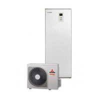
Mitsubishi Heavy Industries RC-HY20 Installation Manual (288 pages)
Air to Water Heat Pump
Brand: Mitsubishi Heavy Industries
|
Category: Heat Pump
|
Size: 33 MB
Table of Contents
-
-
-
Dockings26
-
-
General31
-
Cable Lock36
-
Connection36
-
Hsb6036
-
Power Supply36
-
Hmk6037
-
Power Supply37
-
Power Supply38
-
Rc-Hy20/4038
-
Rc-Hy2050
-
Myupway54
-
Load Monitor55
-
Rc-Hy4055
-
Myupway57
-
-
-
Preparation58
-
-
Start Guide60
-
SG Ready63
-
-
Control
64-
Display Unit64
-
Menu System65
-
Menu List68
-
-
Service
77 -
-
Manage Alarm80
-
Alarm List82
-
-
Accessories
85
-
Fdcw71Vnx
105-
-
Assembly114
-
-
Overflow Valve120
-
Water Circuit123
-
Drain Connection127
-
Dockings128
-
-
General133
-
Cable Lock138
-
Connection138
-
Hsb100138
-
Power Supply138
-
Circuit Breaker139
-
Hmk100139
-
Power Supply139
-
Rc-Hy20/40141
-
Rc-Hy20152
-
Room Sensor BT50152
-
Load Monitor157
-
Myupway157
-
Rc-Hy40157
-
Room Sensor BT50158
-
Myupway159
-
-
-
Preparation160
-
-
Climate System160
-
Hot Water Tank160
-
-
Start Guide162
-
SG Ready165
-
-
Control
166-
Display Unit166
-
Menu System167
-
Menu 3 - Info167
-
-
Service
179 -
-
Manage Alarm182
-
Troubleshooting182
-
Alarm List184
-
-
Accessories
187 -
Technical Data
188
-
-
-
-
Hsb140220
-
-
Overflow Valve221
-
Water Circuit223
-
Dockings227
-
-
-
General231
-
Cable Lock235
-
Connection235
-
Hsb140235
-
Power Supply235
-
Power Supply236
-
Rc-Hy20/40236
-
Rc-Hy20241
-
Room Sensor BT50241
-
Load Monitor245
-
Myupway245
-
Rc-Hy40245
-
Room Sensor BT50246
-
Myupway247
-
-
-
Preparation248
-
-
Climate System248
-
Hot Water Tank248
-
-
Start Guide250
-
SG Ready253
-
-
Control
254-
Display Unit254
-
Menu System255
-
Menu 3 - Info255
-
Menu 5 - Service255
-
-
Service
267 -
-
Manage Alarm270
-
Troubleshooting270
-
Alarm List272
-
-
Accessories
275 -
Technical Data
276
Advertisement

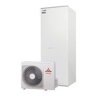
Mitsubishi Heavy Industries RC-HY20 Installation Manual (288 pages)
Air to Water Heat Pump
Brand: Mitsubishi Heavy Industries
|
Category: Water Pump
|
Size: 48 MB
Table of Contents
-
-
-
-
Hsb60 Hmk6018
-
-
Dockings26
-
-
-
General31
-
Cable Lock36
-
Connection36
-
Hsb6036
-
Power Supply36
-
Hmk6037
-
Power Supply37
-
Power Supply38
-
Rc-Hy20/4038
-
Rc-Hy2050
-
Myupway54
-
Load Monitor55
-
Rc-Hy4055
-
Myupway57
-
-
-
Preparation58
-
-
Start Guide60
-
SG Ready63
-
-
Control
64-
Display Unit64
-
Menu System65
-
Menu List68
-
-
Service
77 -
-
Manage Alarm80
-
Alarm List82
-
-
Accessories
85
-
Fdcw71Vnx
105-
-
-
Hsb100 Hmk100120
-
-
Overflow Valve120
-
Water Circuit123
-
Drain Connection127
-
Dockings128
-
-
-
General133
-
Cable Lock138
-
Connection138
-
Hsb100138
-
Power Supply138
-
Circuit Breaker139
-
Hmk100139
-
Power Supply139
-
Power Supply140
-
Rc-Hy20/40140
-
Rc-Hy20152
-
Room Sensor BT50152
-
Load Monitor157
-
Myupway157
-
Rc-Hy40157
-
Room Sensor BT50158
-
Myupway159
-
-
-
Preparation160
-
-
Climate System160
-
Hot Water Tank160
-
-
Start Guide162
-
SG Ready165
-
-
Control
166-
Display Unit166
-
Menu System167
-
Menu 3 - Info167
-
-
Service
179 -
-
Manage Alarm182
-
Troubleshooting182
-
Alarm List184
-
-
Accessories
187 -
Technical Data
188
-
-
-
-
-
Hsb140220
-
-
Overflow Valve221
-
Water Circuit223
-
Dockings227
-
-
-
General231
-
Cable Lock235
-
Connection235
-
Hsb140235
-
Power Supply235
-
Power Supply236
-
Rc-Hy20/40236
-
Rc-Hy20241
-
Room Sensor BT50241
-
Myupway245
-
Rc-Hy40245
-
Room Sensor BT50246
-
Myupway247
-
-
-
Preparation248
-
-
Climate System248
-
Hot Water Tank248
-
-
Start Guide250
-
SG Ready253
-
-
Control
254-
Display Unit254
-
Menu System255
-
Menu 3 - Info255
-
Menu 5 - Service255
-
-
Service
267 -
-
Manage Alarm270
-
Troubleshooting270
-
Alarm List272
-
-
Accessories
275 -
Technical Data
276
Mitsubishi Heavy Industries RC-HY20 User Manual (52 pages)
Air to Water Heat Pump
Brand: Mitsubishi Heavy Industries
|
Category: Heat Pump
|
Size: 2 MB
Table of Contents
-
General
8 -
Quick Guide
10 -
Maintenance
41 -
Checklist
46 -
Glossary
47
Advertisement

Mitsubishi Heavy Industries RC-HY20 User Manual (50 pages)
AIR TO WATER HEAT PUMP
Brand: Mitsubishi Heavy Industries
|
Category: Heat Pump
|
Size: 8 MB
Table of Contents
-
General8
-
Quick Guide10
-
Manage Alarm39
-
Maintenance41
-
Pt300/50042
-
Checklist46
-
Glossary47
Advertisement
Related Products
- Mitsubishi Heavy Industries RC-HY40
- Mitsubishi Heavy Industries RC-HY20-W
- Mitsubishi Heavy Industries RC-HY40-W
- Mitsubishi Heavy Industries eco touch RC-EX1A
- Mitsubishi Heavy Industries RCN-KIT3-E
- Mitsubishi Heavy Industries eco touch RC-EXC3
- Mitsubishi Heavy Industries RC-EX Series
- Mitsubishi Heavy Industries RC-E5
- Mitsubishi Heavy Industries RC-EX3D
- Mitsubishi Heavy Industries RC-EXZ3D