Sign In
Upload
Manuals
Brands
Mitsubishi Heavy Industries Manuals
Air Conditioner
FDC615KXZE1
Mitsubishi Heavy Industries FDC615KXZE1 Manuals
Manuals and User Guides for Mitsubishi Heavy Industries FDC615KXZE1. We have
1
Mitsubishi Heavy Industries FDC615KXZE1 manual available for free PDF download: Service Manual
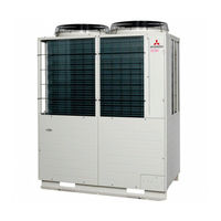
Mitsubishi Heavy Industries FDC615KXZE1 Service Manual (170 pages)
KXZ Standard and Corrosion protection treatment series VRF INVERTER MULTI-SYSTEM AIR-CONDITIONERS
Brand:
Mitsubishi Heavy Industries
| Category:
Air Conditioner
| Size: 18.48 MB
Table of Contents
Service Manual
1
Table of Contents
2
1 Outline of Operation Control by Microcomputer
3
Remote Control (Option Parts)
3
Wired Remote Control Model RC-EX1A
3
Wired Remote Control Model RC-E5
4
Operation Section
5
Wireless Remote Control
5
CPU Reset
6
Operation Control Function by the Wired Remote Control - Model RC-EX1A
6
Power Failure Compensation Function (Electric Power Supply Failure)
6
Switching Sequence of the Operation Mode Switches of Remote Control
6
Operation and Setting from Remote Control
8
Operation Control Function by the Wired Remote Control - Model RC-E5
10
Dehumidifying Operation
11
Operation Control Function by the Indoor Control
11
Operations of Functional Items During Cooling/Heating
11
Timer Operation
11
Combination of Patterns Which Can be Set for the Timer Operations
12
Hot Start (Cold Draft Prevention at Heating)
12
Remote Control Display During the Operation Stop
12
Auto Swing Control (FDT, FDTC, FDTW, FDTS, FDE Only)
13
Hot Keep
13
Cooling
14
Heating
14
Thermostat Operation
14
Fan Control During Cooling Thermostat off
15
Fan Control During Heating Thermostat off
15
Compressor Inching Prevention Control
16
Drain Pump Control
16
Filter Sign
16
Cooling, Dehumidifying Frost Protection
17
Drain Motor (DM) Control
17
Operation Check/Drain Pump Test Run Operation Mode
17
Abnormal Temperature Thermistor (Return Air/Indoor Heat Exchanger) Wire/Short-Circuit Detection
18
Anomalous Fan Motor
18
External Input/Output Control (Cnt or Cnta)
18
High Ceiling Control
18
Output for External Control (Remote Display)
19
Remote Operation Input
19
Operation Permission/Prohibition
20
Selection of Cooling/Heating External Input Function
21
Energy-Saving Operation (RC-EX1A Only), Warm-Up Control (RC-EX1A Only)
22
High Power Operation (RC-EX1A Only)
22
Return Air Temperature Compensation
22
Room Temperature Detection Temperature Compensation During Heating
22
Auto Fan Speed Control (RC-EX1A Only)
23
Home Leave Mode (RC-EX1A Only)
23
IU Overload Alarm (RC-EX1A Only)
23
Peak-Cut Time (RC-EX1A Only)
23
Normal Control
24
Operation Control Function by the Outdoor Control
24
Operation of Major Functional Components under each Operation Mode
24
2 Outdoor Units Combination Use (Model 615, 670)
25
Compressor Control (Master Unit/Slave Unit)
25
Single Use (Model 475, 500, 560 : 2 Compressors Specification)
25
Starting Compressor
25
2 Outdoor Units Combination Use (Model 735)
26
2 Outdoor Units Combination Use (Model 800, 850, 900)
26
2 Outdoor Units Combination Use (Model 950, 1000, 1060, 1120)
26
3 Outdoor Units Combination Use (Model 1200, 1250, 1300, 1350)
27
3 Outdoor Units Combination Use (Model 1425, 1450, 1500, 1560, 1620, 1680)
27
Rotation of Compressor Start/Stop Order
27
Outdoor Fan Control (Master Unit/Slave Unit)
28
Outdoor Fan Control in Cooling Mode
28
Outdoor Fan Control in Heating Mode
28
Outdoor Fan Speed and Fan Motor Rotation Speed
28
Conditions for Finishing Defrost
29
Conditions for Starting Defrost
29
Defrosting (Master Unit/Slave Unit)
29
Discharge Pipe Temperature Control/Error
30
High Pressure Protective Control/Error
30
Low Pressure Protective Control/Error
30
Protective Control
30
Auto Backup Operation
31
Classification of Auto Backup Operations
31
Control Contents of Auto Backup Operation
31
Control after the Conditions to Prohibit the Auto Backup Operation Have Been Established
32
Prohibiting Conditions of Auto Backup Operation
32
Ending Conditions of Test Run Operation
33
Starting Conditions of Test Run Operation
33
Test Run
33
Test Run from Master Outdoor Units with Dip Switches SW5-1 and SW5-2
33
External Input and Demand Input (Master Unit/Slave Unit)
34
Operation Permission or Prohibition Mode
34
Option Controls
34
Demand Control
35
3 Step Demand Control
36
Demand Control from Indoor Unit
37
Silent Mode Control
38
Sound Level (Reference Data) Table
38
Outdoor Fan Snow Protection Control (Master Unit/Slave Unit)
39
Outdoor Operation Mode
39
Example of Operation Mode Selection
40
Reset of Unmatched Condition (Cooling/Heating Unmatched)
41
Emergency Stop Control
42
Forced Cooling /Heating Operation (Master Unit)
42
External Output
43
Operation and Error Signal Output (Master Unit/Slave Unit)
43
Pump down Control for Replacement (Master Unit/Slave Unit)
44
Pump-Down Operation by External Input
45
Sample of System Configuration
46
VTCC: Variable Temperature and Capacity Control (VRF Inverter Multi-System Energy Save Control)
47
7-Segment Display and Operation Data Retention
49
Data Output
49
7-Segment Display
51
Definition of Signal
55
Protection Control Status
55
Compressor Stop Causes
56
Error Retention and Monitoring Data
57
Saving of Operation Data
57
Master/Slave Setting with SW4-7, SW4-8
66
Model Selection with SW4-1 SW4-4
66
Outdoor PCB Setting
66
Indoor PCB Setting
67
Model Selection with SW6-1 - SW6-4 and SW8-1
67
Basics of Troubleshooting
68
2 System Troubleshooting Procedure
68
Explanation of Troubleshooting
69
Checking DC15V on the Control PCB (Step to Check if the Inverter PCB Fails or Not)
69
Inspection of Short-Circuit on the Power Transistor Module Terminals
69
Contents of Troubleshooting
70
List of Inspection Displays
70
Troubleshooting
71
Operates but Does Not Cool
71
Operates but Does Not Heat
72
Earth Leakage Breaker Activated
73
Excessive Noise/Vibration
74
Louver Motor Anomaly
77
Power Supply System Anomaly (Power Supply to Indoor Unit PCB)
78
Power Supply System Error (Power Supply to Remote Control)
79
Wait
80
No Display
86
Remote Control Communication Error
87
Duplicated Indoor Unit Address
88
Outdoor Unit Signal Line Error
89
Communication Error During Operation
90
Indoor Heat Exchanger Temperature Thermistor Anomaly (Thi-R)
91
Indoor Return Air Temperature Thermistor Anomaly (Thi-A)
92
Drain Trouble
93
Excessive Number of Indoor Units (more than 17 Units) by Controlling One Remote Control
94
Address Setting Error between Master and Slave Indoor Units
95
Address Setting Error by Mixed Setting Method
96
Indoor Fan Motor Anomaly (FDT, FDTC, FDTW, FDTS, FDU, FDUM, FDK, FDUT71, FDFW Series)
97
Address Setting Error of Master and Slave Indoor Units
98
Indoor Unit Operation Check, Drain Motor Check Mode Anomaly
99
Indoor Fan Motor Rotation Speed Anomaly
100
Defective Panel Switch Operation (FDT)
101
Remote Control Temperature Thermistor Anomaly (Thc)
102
Duplicated Outdoor Unit Address No.
103
Open L3 Phase on Power Supply at Primary Side
104
Discharge Pipe Temperature Error (Tho-D1, D2)
105
Outdoor Heat Exchanger Temperature Thermistor (Tho-R) and Subcooling Coil Temperature Thermistor (Tho-SC,-H) Anomaly
106
Outdoor Air Temperature Thermistor Anomaly (Tho-A)
107
Discharge Pipe Temperature Thermistor Anomaly (Tho-D1, D2)
108
High Pressure Anomaly (63H1-1, 2 Activated)
109
Power Transistor Overheat
110
Current Cut (CM1, CM2)
111
Excessive Number of Indoor Units Connected, Excessive Total Capacity of Connection
112
Liquid Flooding Anomaly (CM1, CM2)
113
E45 Communication Error between Inverter PCB and Outdoor Control PCB
114
Mixed Address Setting Methods Coexistent in same Network
115
Outdoor DC Fan Motor Anomaly
116
E49 Low Pressure Anomaly
118
Suction Pipe Temperature Thermistor Anomaly (Tho-S), Under-Dome Temperature Thermistor Anomaly (Tho-C1, C2)
119
High Pressure Sensor Anomaly (PSH), Low Pressure Sensor Anomaly (PSL)
120
Power Transistor Temperature Thermistor Anomaly (Tho-P1, P2)
121
Anomalous Compressor by Loss of Synchronism
122
Compressor Startup Failure (CM1,CM2)
123
Communications Error between the Master Unit and Slave Units
124
Emergency Stop
125
Outdoor Unit Control PCB Replacement Procedure
126
Precautions for Safety
126
To Exchange the Control PCB
126
Voltage Measurement Points
127
Outdoor Unit Inverter PCB Replacement Procedure
128
Installation Method to Power Transistor
129
Outdoor Unit Transistor Module Replacement Procedure
130
To Exchange the Transistor Module
130
Function of Dip Switch for Control (SW3, 4, 5)
131
Function of Jumper Wire (J13, 15)
131
Function of Connection
132
Electircal Wiring - Models FDC280KXZE1, 335KXZE1, FDCS280KXZE1 335KXZE1
133
Electircal Wiring - Models FDC400KXZE1, 450KXZE1, FDCS400KXZE1, 450KXZE1
134
Electircal Wiring - Models FDC475KXZE1, 500KXZE1, 560KXZE1, FDCS475KXZE1, 500KXZE1, 560KXZE1
135
Piping System - Models FDC280KXZE1, 335KXZE1, FDCS280KXZE1, 335KXZE1
136
Piping System - Models FDC400KXZE1, 450KXZE1, FDCS400KXZE1, 450KXZE1
137
Piping System - Models FDC475KXZE1, 500KXZE1, 560KXZE1, FDCS475KXZE1, 500KXZE1, 560KXZE1
138
5 Application Data
139
Installation of Outdoor Unit
139
Acessory
140
Before Beginning Installation
140
Combination Patterns
140
Optional Parts
140
Installation Space (Service Space) Example
141
Selecting the Installation Location
141
Unit Delivery and Installation
141
Piping Material Selection
142
Refrigerant Piping
142
Restrictions on the Use of Pipes
142
Pipe Size Selection
143
Selection of an Indoor Unit Side Branching Pipe Set
144
Selection of an Outdoor Unit Side Branching Pipe Set
144
Pipe Connection Position and Pipe Direction
145
Operation Procedure
146
Piping Work
146
Additional Oil Charge
147
Air Tightness Test and Air Purge
147
Method of Operating Service Valves
147
Vacuuming
147
Additional Refrigerant Charge
148
Heating and Condensation Prevention
148
Drainage
149
Electrical Wiring Work
149
Wiring System Diagrams
149
Indoor Unit Power Supply Specifications: Single Phase 220-240V
150
Method of Connecting Power Cables
150
Outdoor Unit Power Supply Specifications
150
Indoor and Outdoor Units Signal Cables
151
Method of Connecting Signaling Wires
151
Remote Control Wiring Specifications
151
Controller Settings
152
Unit Address Setting
152
Automatic Address Setting
153
Manual Address Setting
153
Summary of Address Setting Methods
153
Address Change (Available Only with New SL)
155
Operating Procedure
155
When Single Indoor Unit Is Connected to the Remote Control
155
7-Segment Display Indication in Automatic Address Setting
156
When Plural Indoor Units Are Connected to the Remote Control
156
Address Setting Failure Indication
157
Change of Control
157
External Input and Outpue Terminals Specifications
158
Before Starting Test Operation
159
Check Operation
159
Display on 7-Segment Indicator During Check Operation
159
Test Operation and Transfer
159
Confirmation before Implementing the Refrigerant Quantity Check
160
Error Display on 7-Segment Indicator after Ending the Check Operation
160
Guideline of Accuracy
160
Refrigerant Quantity Check
160
Test Operation
160
After the Refrigerant Quantity Check Operation
161
Method of Refrigerant Quantity Check Operation
161
Cautions for Servicing (for R410A and Compatible Machines)
162
Test Operation
162
Transfer
162
The Calculation of Reduction Refrigerant Quantity (E)
163
Instructions for Installing the Branch Pipe Set
164
The Branch Pipe Set Installation Procedure
165
How to Select a Branching Pipe
166
How to Select a Header Set
166
Method to Select a Branch Pipe Set (Type DIS)
166
Example 1: Branching Type Configuration
167
Example 2: Header Type Configuration
167
Example 3: Branching + Header Mixed Type Configuration
167
Assembly and Removal of Front Panel
168
Location of Claws on Front Panel
168
Point of Change
168
Procedure to Attach or Remove the Front Panel
168
Advertisement
Advertisement
Related Products
Mitsubishi Heavy Industries FDC615KXZRXE1
Mitsubishi Heavy Industries FDC615KXZWE1
Mitsubishi Heavy Industries FDC615KXZXE1
Mitsubishi Heavy Industries FDC670KXZE1
Mitsubishi Heavy Industries FDC670KXZRXE1
Mitsubishi Heavy Industries FDC670KXZWE1
Mitsubishi Heavy Industries FDC670KXZXE1
Mitsubishi Heavy Industries FDC1620KXZE1
Mitsubishi Heavy Industries FDC112KXZES1
Mitsubishi Heavy Industries FDC258
Mitsubishi Heavy Industries Categories
Air Conditioner
Remote Control
Heat Pump
Engine
Control Systems
More Mitsubishi Heavy Industries Manuals
Login
Sign In
OR
Sign in with Facebook
Sign in with Google
Upload manual
Upload from disk
Upload from URL