Sign In
Upload
Manuals
Brands
Mitsubishi Electric Manuals
Air Conditioner
PEV-P200YM-A
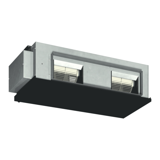
Mitsubishi Electric PEV-P200YM-A Manuals
Manuals and User Guides for Mitsubishi Electric PEV-P200YM-A. We have
2
Mitsubishi Electric PEV-P200YM-A manuals available for free PDF download: Service Handbook, Operation Manual
Mitsubishi Electric PEV-P200YM-A Service Handbook (272 pages)
Brand:
Mitsubishi Electric
| Category:
Air Conditioner
| Size: 13 MB
Table of Contents
Safety Precautions
2
General Precautions
2
Transportation and Installation
4
Piping Work
5
Wiring Work
6
Relocation and Repairs
7
Additional Precautions
7
Table of Contents
10
Chapter 1 Check before Servicing
12
Preparation for Piping Work
14
Read before Servicing
14
Tool Preparation
15
Handling and Characteristics of Piping Materials, Refrigerant, and Refrigerant Oil
17
Piping Materials
17
Storage of Piping Materials
19
Pipe Processing
19
Characteristics of the New and Conventional Refrigerants
20
Refrigerant Oil
21
Working with Refrigerant Piping
22
Pipe Brazing
22
Air Tightness Test
23
Vacuum Drying
24
Refrigerant Charging
25
Precautions for Wiring
26
Chapter 2 Restrictions
28
System Configurations
30
Types and Maximum Allowable Length of Cables
31
Control Wiring
31
Switch Settings
32
M-NET Address Settings
33
Address Settings List
33
Outdoor Unit Power Jumper Connector Connection
33
Outdoor Unit Centralized Controller Switch Setting
34
Room Temperature Detection Position Selection
34
Start/Stop Control of Indoor Units
34
Example System with an MA Remote Controller
35
Single Refrigerant System
35
Grouped Operation of Units in Separate Refrigerant Circuits
37
System with a Connection of System Controller to Centralized Control Transmission Line
39
Restrictions on Refrigerant Pipes
41
Restrictions on Refrigerant Pipe Length
41
Restrictions on Refrigerant Pipe Size
42
Chapter 3 Major Components, Their Functions and Refrigerant Circuits
44
External Appearance and Refrigerant Circuit Components of Outdoor Unit
46
External Appearance of Outdoor Unit
46
Outdoor Unit Refrigerant Circuits
50
Outdoor Unit Refrigerant Circuit Diagrams
54
Functions of the Major Components of Outdoor Unit
56
External Appearance of Indoor Unit
59
Indoor Unit Outline Diagrams
64
Floor-Standing
64
Indoor Unit Refrigerant Circuit Diagrams
71
Functions of the Major Components of Indoor Unit
73
Chapter 4 Electrical Components and Wiring Diagrams
76
Outdoor Unit Circuit Board Arrangement
78
Outdoor Unit Control Box
78
Terminal Box
79
Outdoor Unit Circuit Board Components
80
Control Board
80
M-NET Board (Transmission Power Supply Board)
81
INV Board
82
Fan Board
83
Noise Filter
85
Outdoor Unit Electrical Wiring Diagrams
86
Transmission Booster Electrical Wiring Diagrams
89
Indoor Unit Circuit Board Arrangement
90
Indoor Unit Circuit Board Components
92
Control Board
92
Sub Board
93
Indoor Unit Electrical Wiring Diagrams
94
Chapter 5 Control
98
Dipswitch Functions and Factory Settings
100
Outdoor Unit Switch Functions and Factory Settings
100
Indoor Unit Switch Functions and Factory Settings
103
Dip Switches
103
Address Switch
103
Outdoor Unit Control
104
Overview (PUCY-P250YKA Model Only)
104
Rotation Control (PUCY-P250YKA Model Only)
104
Initial Control
104
Startup Control
104
Refrigerant Bypass Control
105
Frequency Control
106
Refrigerant Recovery Control
106
Outdoor Unit Fan Control
107
Subcool Coil Control (Linear Expansion Valve 1)
107
Refrigerant Flow Control (Linear Expansion Valve 2) (PUCY-P250YKA Model Only)
107
Control at Initial Startup
108
Emergency Operation Mode (PUCY-P250YKA Model Only)
109
Operation Mode
111
Operation Flowcharts
112
Operation Sequence Flowchart
112
Actions Performed in Different Modes
114
Chapter 6 Test Run
116
Read before Test Run
118
Making Interlock Settings from an MA Remote Controller
119
MA Remote Controller (PAR-31MAAE)
119
Changing the Room Temperature Detection Position
120
Test Run Method
121
MA Remote Controller (PAR-31MAAE)
121
Operation Characteristics and Refrigerant Charge
123
Evaluating and Adjusting Refrigerant Charge
123
Refrigerant Overcharge and Undercharge
123
Checking the Refrigerant Charge During Operation
123
The Amount of Refrigerant to be Added
124
Operation
125
Refrigerant Charge Adjustment Mode
125
The Following Symptoms Are Normal
127
Standard Operation Data (Reference Data)
128
Single Unit (Standard)
128
Chapter 7 Troubleshooting Using Error Codes
130
Error Code and Preliminary Error Code Lists
132
Error Code Definitions and Solutions: Codes [0 - 999]
135
Error Code [0403]
135
Error Code Definitions and Solutions: Codes [1000 - 1999]
136
Error Code [1102]
136
Error Code [1301]
137
Error Code [1302] (During Operation)
138
Error Code [1302] (at Startup)
139
Error Code [1500]
139
Error Code Definitions and Solutions: Codes [4000 - 4999]
140
Error Code [4102]
140
Error Code [4106]
141
Error Code [4109]
141
Error Code [4115]
142
Error Code [4116]
142
Error Code [4121]
143
Error Codes [4220, 4225] Detail Code 108
144
Error Codes [4220, 4225] Detail Code 109
145
Error Codes [4220, 4225] Detail Code 111
146
Error Codes [4220, 4225] Detail Code 131
147
Error Code [4230]
147
Error Code [4240]
148
Error Codes [4250, 4255] Detail Code 101
149
Error Code [4250] Detail Codes 106 and 107
150
Error Codes [4250, 4255] Detail Code 104
151
Error Codes [4250, 4255] Detail Code 105
152
Error Code [4260]
152
Error Code Definitions and Solutions: Codes [5000 - 5999]
153
Error Codes [5101, 5102, 5103, 5104]
153
Error Codes [5102, 5103, 5104, 5106, 5107]
154
Error Code [5110]
155
Error Code [5201]
155
Error Code [5301] Detail Code 115
156
Error Code [5301] Detail Code 117
156
Error Code [5301] Detail Code 119
157
Error Code [5301] Detail Code 120
157
Error Code [5305] Detail Code 132
158
Error Code [5305] Detail Code 133
158
Error Codes [5305] Detail Code 134
159
Error Code Definitions and Solutions: Codes [6000 - 6999]
160
Error Code [6201]
160
Error Code [6202]
160
Error Code [6600]
161
Error Code [6601]
161
Error Code [6602]
162
Error Code [6603]
163
Error Code [6606]
163
Error Code [6607] Error Source Address = Outdoor Unit (OC)
164
Error Code [6607] Error Source Address = Indoor Unit (IC)
165
Error Code [6607] Error Source Address = LOSSNAY (LC)
166
Error Code [6607] Error Source Address = System Controller
167
Error Code [6607] All Error Source Addresses
168
Error Code [6607] no Error Source Address
169
Error Code [6608]
170
Error Code [6831]
171
Error Code [6832]
172
Error Code [6833]
173
Error Code [6834]
174
Error Code Definitions and Solutions: Codes [7000 - 7999]
175
Error Code [7100]
175
Error Code [7101]
176
Error Code [7102]
177
Error Code [7105]
178
Error Code [7106]
178
Error Code [7110]
179
Error Code [7111]
179
Error Code [7113]
180
Error Code [7117]
181
Error Code [7130]
182
MA Remote Controller Problems
186
The LCD Does Not Light up
186
The LCD Momentarily Lights up and then Goes off
187
PLEASE WAIT" Do Not Go off the Screen
188
Air Conditioning Units Do Not Operate When the on Button Is Pressed
189
Refrigerant Control Problems
190
Units in the Cooling Mode Do Not Operate at Expected Capacity
190
Outdoor Units Stop at Irregular Times
192
Checking Transmission Waveform and for Electrical Noise Interference
193
M-Net
193
MA Remote Controller
195
Pressure Sensor Circuit Configuration and Troubleshooting Pressure Sensor Problems
196
Comparing the High-Pressure Sensor Measurement and Gauge Pressure
196
High-Pressure Sensor Configuration (63HS1)
196
Comparing the Low-Pressure Sensor Measurement and Gauge Pressure
197
Low-Pressure Sensor Configuration (63LS)
197
Troubleshooting Solenoid Valve Problems
198
Troubleshooting Outdoor Unit Fan Problems
199
Troubleshooting LEV Problems
200
General Overview on LEV Operation
200
Possible Problems and Solutions
203
Coil Removal Instructions
204
Troubleshooting Inverter Problems
206
Inverter-Related Problems and Solutions
206
Checking the Inverter Board Error Detection Circuit
208
Checking the Compressor for Ground Fault and Coil Resistance Problems
208
Checking the Inverter for Damage at No-Load
208
Checking the Inverter for Damage During Compressor Operation
209
Checking the Fan Motor for Ground Fault and Coil Resistance Problems
209
Checking the Fan Board for Problems
210
Checking the Fan Board Error Detection Circuit at no Load
210
Checking the Fan Inverter for Damage at no Load
211
Checking the Fan Inverter for Damage with Load
212
Checking the Installation Conditions
212
Solutions for the Main No-Fuse Breaker Trip
213
Solutions for the Main Earth Leakage Breaker Trip
213
Simple Check on Inverter Circuit Components
214
Troubleshooting Problems with IGBT Module
214
Control Circuit
216
Control Power Supply Function Block
216
Troubleshooting Problems with Outdoor Unit Transmission Power Supply Circuit
219
8-10 Measures for Refrigerant Leakage
220
8-11 Indoor Unit Fan
222
Step 8 (Enlarged View)
223
Step15 (Side View)
225
8-12 Compressor Replacement Instructions
230
Troubleshooting Problems Using the LED Status Indicators on the Outdoor Unit
234
Chapter 9 LED Status Indicators on the Outdoor Unit Circuit Board
236
LED Status Indicators
238
How to Read the LED
238
Initial LED Display
239
Clock Memory Function
240
LED Status Indicators Table
241
Advertisement
Mitsubishi Electric PEV-P200YM-A Operation Manual (47 pages)
Brand:
Mitsubishi Electric
| Category:
Air Conditioner
| Size: 10 MB
Advertisement
Related Products
Mitsubishi Electric PEV-P250YM-A
Mitsubishi Electric PEV-P400YM-A
Mitsubishi Electric PEV-P500YM-A
Mitsubishi Electric CITY MULTI PEFY-P08NMAU-E
Mitsubishi Electric PEAD-RP2.5GA
Mitsubishi Electric CITY MULTI PEFY-W25VMA-A
Mitsubishi Electric PEH-10MYA
Mitsubishi Electric Mr. Slim PEAD-SP140JA
Mitsubishi Electric CITY MULTI PEFY-P36VMS-E-S
Mitsubishi Electric Mr. SLIM PEAD-(S)M60JA(L)(2)
Mitsubishi Electric Categories
Air Conditioner
Controller
Projector
Inverter
Heat Pump
More Mitsubishi Electric Manuals
Login
Sign In
OR
Sign in with Facebook
Sign in with Google
Upload manual
Upload from disk
Upload from URL