Sign In
Upload
Manuals
Brands
Mitsubishi Electric Manuals
Inverter
FR-A870-02860-E
Mitsubishi Electric FR-A870-02860-E Manuals
Manuals and User Guides for Mitsubishi Electric FR-A870-02860-E. We have
2
Mitsubishi Electric FR-A870-02860-E manuals available for free PDF download: Instruction Manual, Assembly & Installation Manuallines
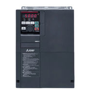
Mitsubishi Electric FR-A870-02860-E Instruction Manual (674 pages)
Brand:
Mitsubishi Electric
| Category:
Inverter
| Size: 16 MB
Table of Contents
Table of Contents
3
Basic Operation
8
Operation Steps
9
About the Related Manuals
10
Components of the Operation Panel (FR-DU08)
11
Basic Operation of the Operation Panel
13
Parameter Setting Mode
14
Digital Characters and Their Corresponding Printed Equivalents
14
Changing the Parameter Setting Value
15
Monitoring the Inverter
16
Monitoring of Output Current and Output Voltage
16
First Priority Monitor Screen
16
Displaying the Set Frequency
16
Easy Setting of the Inverter Operation Mode
17
Frequently-Used Parameters (Simple Mode Parameters)
19
Simple Mode Parameter List
19
Simple Mode Parameter
20
Basic Operation Procedure (PU Operation)
21
Setting the Frequency on the Operation Panel
21
Perform PU Operation Using the Setting Dial Like a Potentiometer
22
Setting the Frequency with Switches (Multispeed Setting)
23
Setting the Frequency Using an Analog Signal (Voltage Input)
24
Setting the Frequency Using an Analog Signal (Current Input)
25
Basic Operation Procedure (External Operation)
26
Changing the Frequency (60 Hz, Initial Value) at the Maximum Voltage Input (5 V, Initial Value)
30
Changing the Frequency (60 Hz, Initial Value) at the Maximum Current Input (at 20 Ma, Initial Value)
32
Basic Operation Procedure (JOG Operation)
33
Giving a Start Command by Using External Signals for JOG Operation
33
Giving a Start Command from the Operation Panel for JOG Operation
34
Parameter List (by Parameter Number)
37
Use of a Function Group Number for the Identification of Parameters
63
Parameter List (by Function Group)
64
N: Communication Operation Parameters
71
Control Method
74
Real Sensorless Vector Control
74
Vector Control
75
Vector Control and Real Sensorless Vector Control
76
Changing the Control Method
79
Motor Capacity
79
Selecting the Advanced Magnetic Flux Vector Control
85
Control Block Diagram
88
Setting Procedure of Real Sensorless Vector Control (Speed Control)
90
Setting Procedure of Vector Control (Speed Control)
92
Setting the Torque Limit Level
93
Operation
94
Performing High-Accuracy, Fast-Response Control (Gain Adjustment for Real Sensorless Vector Control and Vector Control)
102
Initial Setting Value
102
Adjustment Method
106
Troubleshooting in the Speed Control
109
Speed Feed Forward Control and Model Adaptive Speed Control
111
Torque Bias
113
Block Diagram
113
Avoiding Motor Overrunning
117
Speed Limit (Pr.873)
117
Notch Filter
119
Torque Control under Real Sensorless Vector Control and Vector Control
120
Torque Control
120
Polarity of Torque Command
123
Setting Procedure of Real Sensorless Vector Control (Torque Control)
124
Setting Procedure for Vector Control (Torque Control)
126
Torque Command
127
Control Block Diagram
127
Speed Limit
132
Torque Control Gain Adjustment
138
Adjustment Procedure
139
Troubleshooting in Torque Control
139
Torque Control by Variable-Current Limiter Control
140
Position Control under Vector Control
141
About Position Control
141
Control Block Diagram
141
Operation Example
142
Setting Procedure of Vector Control (Position Control)
143
Position Command Source Selection
144
Simple Positioning Function by Parameters
145
Acceleration/Deceleration Time
149
Operation Panel Indication
155
Position Control by the Pulse Train Input to the FR-A8AL
159
Wiring Example
160
Operation Outline
160
Interface of the Positioning Module and Inverter
161
Output Type
161
Hardware Configuration
161
Position Control by Inverter Pulse Train Input
162
Clear Signal Selection
163
Pulse Monitor
164
Pulse Monitor Selection (Pr.430)
164
Electronic Gear Setting
168
Position Adjustment Parameter Settings
170
Position Control Gain Adjustment
172
Troubleshooting in Position Control
173
Real Sensorless Vector Control, Vector Control Adjustment
175
Speed Detection Filter and Torque Detection Filter
175
Excitation Ratio
176
E) Environment Setting Parameters
177
Real Time Clock Function
178
(E) Environment Setting Parameters
179
Reset Selection/Disconnected PU Detection/Pu Stop Selection
180
PU Display Language Selection
183
Buzzer Control
183
PU Contrast Adjustment
183
Display-Off Mode
183
Direct Setting
184
Resetting USB Host Errors
184
Setting Dial Potentiometer Mode/Key Lock Operation Selection
185
Frequency Change Increment Amount Setting
186
Multiple Rating Setting
187
Using a 600 VAC Power Supply
188
Parameter Write Selection
189
Password Function
191
Communication Option
192
Operation
192
Free Parameter 1
193
Setting Multiple Parameters as a Batch
193
Extended Parameter Display and User Group Function
197
PWM Carrier Frequency and Soft-PWM Control
199
Inverter Parts Life Display
201
Maintenance Timer Alarm
205
Current Average Value Monitor Signal
206
F) Setting of Acceleration/Deceleration Time and Acceleration/Deceleration Pattern
208
Setting the Acceleration and Deceleration Time
208
Acceleration/Deceleration Time
211
Acceleration/Deceleration Pattern
213
Acceleration/Deceleration Pattern Selection
213
Remote Setting Function
218
Starting Frequency and Start-Time Hold Function
222
Shortest Acceleration/Deceleration and Optimum Acceleration/Deceleration (Automatic Acceleration/Deceleration)
223
Lift Operation (Automatic Acceleration/Deceleration)
226
D) Operation Command and Frequency Command
228
Operation Mode Selection
229
(D) Operation Command and Frequency Command
231
Startup in Network Operation Mode at Power-ON
238
Start Command Source and Frequency Command Source During Communication Operation
239
Fault Record
243
Reverse Rotation Prevention Selection
246
Frequency Setting Via Pulse Train Input
247
Wiring Length
249
Specification
249
JOG Operation
250
Operation by Multi-Speed Setting
252
H) Protective Function Parameter
254
Motor Overheat Protection (Electronic Thermal O/L Relay)
255
(H) Protective Function Parameter
257
Fault Definition
261
Cooling Fan Operation Selection
262
Earth (Ground) Fault Detection at Start
263
Initiating a Protective Function
263
I/O Phase Loss Protection Selection
264
Initial Setting Value
264
Retry Function
265
Limiting the Output Frequency (Maximum/Minimum Frequency)
267
Avoiding the Mechanical Resonance Points (Frequency Jump)
268
Stall Prevention Operation
270
Operation
274
Load Characteristics Fault Detection
277
Setting Example
280
Motor Overspeeding Detection
281
Monitor Display and Monitor Output Signal
282
M) Monitor Display and Monitor Output Signal
282
Speed Display and Rotations Per Minute Setting
283
Monitor Indicator Selection Using Operation Panel or Via Communication
285
(M) Monitor Display and Monitor Output Signal
287
Monitor Description
292
Monitor Display Selection for Terminals FM/CA and am
296
Adjustment of Terminal FM/CA and Terminal am
302
Operation
303
Energy Saving Monitor
306
Output Terminal Function Selection
311
Output Signal List
312
Output Signal
317
Output Frequency Detection
319
Control Method
321
Output Current Detection Function
322
Output Torque Detection
324
Remote Output Function
324
Analog Remote Output Function
326
Fault Code Output Selection
328
Pulse Train Output of Output Power
329
Detection of Control Circuit Temperature
330
Encoder Pulse Dividing Output
330
T) Multi-Function Input Terminal Parameters
331
Analog Input Selection
332
(T) Multi-Function Input Terminal Parameters
333
Analog Input Terminal (Terminal 1, 4) Function Assignment
336
Analog Input Compensation
337
Analog Input Responsiveness and Noise Elimination
339
Frequency Setting Voltage (Current) Bias and Gain
341
Operation
345
Bias and Gain for Torque (Magnetic Flux) and Set Voltage (Current)
347
Checking of Current Input on Analog Input Terminal
352
Input Terminal Function Selection
356
Inverter Output Shutoff Signal
360
Changing the X10 Signal Input Specification (for Separated Converter Type)
361
External Fault Input Signal
362
Selecting Operation Condition of the Second Function Selection Signal (RT) and the Third Function Selection Signal (X9)
362
Start Signal Operation Selection
364
Low Flow Rate Input Warning
366
Input Signal Status
366
C) Motor Constant Parameters
367
Applied Motor
367
Offline Auto Tuning
370
Error Display
375
Online Auto Tuning
379
Parameter Settings for a Motor with Encoder
382
Parameter Settings for the Motor under Vector Control
382
Signal Loss Detection of Encoder Signals
382
A) Application Parameters
383
Application Parameters
383
Electronic Bypass Function
384
Connection Diagram
385
Converter Status
389
Self Power Management
390
Brake Sequence Function
393
Protective Function
397
Start Count Monitor
398
Stop-On-Contact Control
399
Input Signal
401
Load Torque High Speed Frequency Control
402
Traverse Function
405
Anti-Sway Control
407
Orientation Control
409
Function and Description
417
PID Control
424
Input/Output Signals
430
Calibration Example
434
Changing the Display Increment of the Numerical Values Used in PID Control
437
PID Pre-Charge Function
440
Dancer Control
444
Input Method
447
Calibration Parameter
447
Automatic Restart after Instantaneous Power Failure/Flying Start with an Induction Motor
451
Offline Auto Tuning for a Frequency Search
457
Power Failure Time Deceleration-To-Stop Function
461
Connection and Parameter Setting
461
PLC Function
466
Trace Function
469
Operating Status
477
N) Operation Via Communication and Its Settings
478
Wiring and Configuration of PU Connector
478
Wiring and Configuration of RS-485 Terminals
480
Initial Setting of Operation Via Communication
483
Communication EEPROM Write Selection (Pr.342)
483
Operation Mode Switching and Communication Startup Mode (Pr.79, Pr.340)
488
Initial Settings and Specifications of RS-485 Communication
490
Mitsubishi Inverter Protocol (Computer Link Communication)
492
Communication Procedure
492
Data Definitions
495
Error Description
496
Response Time
496
Setting Items and Set Data
501
Data Description
501
Operation Command
504
MODBUS RTU Communication Specification
506
Message Format
507
Function Code List
509
Error Response
515
MODBUS Register
516
USB Device Communication
521
Automatic Connection with GOT
522
Backup/Restore
523
Connected Devices
523
G) Control Parameters
525
Control Parameters
525
Manual Torque Boost
526
Base Frequency, Voltage
527
Load Pattern Selection
528
Excitation Current Low-Speed Scaling Factor
530
Energy Saving Control
531
Energy Saving Operation (Setting "4")
531
Optimum Excitation Control (Setting "9")
531
Adjustable 5 Points V/F
532
DC Injection Brake, Zero Speed Control, and Servo Lock
533
Control Method
537
Deceleration Stop
537
Output Stop Function
538
Stop Selection
539
Regenerative Brake Selection (Built-In Brake Transistor Model Only)
541
Selection between Resetting or Not Resetting During Power Supply to Main Circuit
542
Regeneration Avoidance Function
543
Increased Magnetic Excitation Deceleration
545
Slip Compensation
546
Encoder Feedback Control
547
Droop Control
549
Operation
550
Speed Smoothing Control
552
Setting Method
552
Parameter Clear / All Parameter Clear
553
Copying and Verifying Parameters on the Operation Panel
554
Parameter Copy
554
Parameter Verification
556
Copying and Verifying Parameters Using USB Memory
557
Checking Parameters Changed from Their Initial Values (Initial Value Change List)
560
Protective Functions
562
Inverter Fault and Alarm Indications
563
Reset Method for the Protective Functions
563
Check and Clear of the Fault History
564
The List of Fault Displays
566
Error Message
566
Causes and Corrective Actions
568
Check First When You Have a Trouble
587
Motor Does Not Start
587
Motor or Machine Is Making Abnormal Acoustic Noise
589
Inverter Generates Abnormal Noise
589
Motor Generates Heat Abnormally
590
Motor Rotates in the Opposite Direction
590
Speed Greatly Differs from the Setting
590
Acceleration/Deceleration Is Not Smooth
591
Speed Varies During Operation
591
Operation Mode Is Not Changed Properly
592
Operation Panel (FR-DU08) Display Is Not Operating
592
Motor Current Is too Large
592
Speed Does Not Accelerate
593
Unable to Write Parameter Setting
594
Power Lamp Is Not Lit
594
Appendix
596
Appendix 1 Parameters (Functions) and Instruction Codes under Different Control Methods
597
Appendix 2 Details of the Ready Bit of Communication Options (FR-A8ND and FR-A8NF)
619
Appendix 3 for Customers Using HMS Network Options
620
List of Inverter Monitored Items / Command Items
620
Direct Command Mode for Position Control
624
PLC Function
631
Emergency Drive
636
Emergency Drive (Fire Mode)
658
Connection Example
659
Advertisement
Mitsubishi Electric FR-A870-02860-E Assembly & Installation Manuallines (56 pages)
Brand:
Mitsubishi Electric
| Category:
Inverter
| Size: 3 MB
Table of Contents
Table of Contents
1
Installation and Instructions
7
Wiring
10
Failsafe of the System Which Uses the Inverter
24
Precautions for Use of the Inverter
25
Basic Operation
27
Troubleshooting
44
Specifications
47
Aappendix
50
Advertisement
Related Products
Mitsubishi Electric FR-A870-02300-E
Mitsubishi Electric FR-A872-E
Mitsubishi Electric FR-A872-05690-E
Mitsubishi Electric FR-A872-06470-E
Mitsubishi Electric FR-A872-07150-E
Mitsubishi Electric FR-A872-P
Mitsubishi Electric FR-A820-01250-GF (22K)
Mitsubishi Electric FR-A840-04320-GF (160K)
Mitsubishi Electric FR-A840-02600-E-R2R
Mitsubishi Electric FR-A802-10940-P
Mitsubishi Electric Categories
Air Conditioner
Controller
Projector
Inverter
Heat Pump
More Mitsubishi Electric Manuals
Login
Sign In
OR
Sign in with Facebook
Sign in with Google
Upload manual
Upload from disk
Upload from URL