Sign In
Upload
Manuals
Brands
Mitsubishi Electric Manuals
Media Converter
CC2 Series
Mitsubishi Electric CC2 Series Manuals
Manuals and User Guides for Mitsubishi Electric CC2 Series. We have
2
Mitsubishi Electric CC2 Series manuals available for free PDF download: Instruction Manual
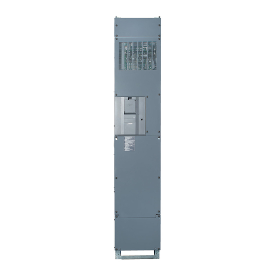
Mitsubishi Electric CC2 Series Instruction Manual (212 pages)
Converter Unit
Brand:
Mitsubishi Electric
| Category:
Inverter
| Size: 7 MB
Table of Contents
Table of Contents
2
Safety Instructions
7
General Instruction
10
Chapter 1 INTRODUCTION
12
Harmonic Suppression Guidelines
13
Product Checking and Accessories
14
Component Names
15
Related Manuals
17
Chapter 2 INSTALLATION and WIRING
19
Peripheral Devices
19
Converter Unit and Peripheral Devices
19
Peripheral Devices
21
Compatible Inverters
21
Removal and Reinstallation of the Cover
24
Installation of the Converter Unit and Enclosure Design
28
Converter Unit Installation Environment
28
Cooling System Types for Converter Unit Enclosure
30
Installation of the Converter Unit
31
Terminal Connection Diagrams
33
Main Circuit Terminals (for 6-Phase Rectification)
36
Details on the Main Circuit Terminals
36
Terminal Layout of the Main Circuit Terminals, Wiring of Power Supply and the Inverter
37
Wiring Connection
44
Recommended Cables
47
Connecting Cables
47
Earthing (Grounding) Precautions
48
Main Circuit Terminals (for 12-Phase Rectification)
49
Details on the Main Circuit Terminals
49
Connection Diagram with 12-Phase Rectifier Power Transformer
49
12-Phase Rectifier Power Transformer
49
Wiring Method
50
Recommended Cables
51
Earthing (Grounding) Precautions
52
Control Circuit
53
Details on the Control Circuit Terminals
53
Input Signal
53
Output Signal
54
Common Terminal
54
Control Logic (Sink/Source) Change
55
Wiring of Control Circuit
57
Control Circuit Terminal Layout
57
Signal Inputs by Contactless Switches
59
Wiring Precautions
59
When Using Separate Power Supplies for the Control Circuit and the Main Circuit
60
Connection Method
60
When Supplying 24 V External Power to the Control Circuit
61
Communication Connectors and Terminals
64
PU Connector
64
Communication Operation
64
Terminal Block
65
RS-485 Terminal Block
65
Electro-Magnetic Interference (EMI) and Leakage Currents
67
Leakage Currents and Countermeasures
67
Techniques and Measures for Electromagnetic Compatibility (EMC)
69
Built-In EMC Filter
71
Power Supply Harmonics
73
Harmonic Suppression Guidelines in Japan
73
Installation of a Reactor
77
Power Shutdown and Magnetic Contactor (MC)
78
Checklist before Starting Operation
80
Chapter 4 BASIC OPERATION
82
Operation Panel
83
Components of the Operation Panel
83
Basic Operation of the Operation Panel
84
Parameter Setting Mode
85
Digital Characters and Their Corresponding Printed Equivalents
85
Changing the Parameter Setting Value
86
Monitoring the Converter Unit Status
87
Monitoring of Converter Output Voltage and Input Current
87
First Priority Monitor Screen
87
Chapter 5 PARAMETERS
88
Parameter List
89
Parameter List (by Parameter Number)
89
The Function Group Number Is Used for the Identification of Parameters, and Displayed in Alphanumeric Order
91
Parameter List (by Function Group Number)
93
A: Application Parameters
94
E) Environment Setting Parameters
95
Simple Clock Function
95
Reset Selection / Disconnected PU Detection / Reset Limit
96
Buzzer Control
97
Display-Off Setting
97
Disabling the Setting Dial and Keys on the Operation Panel
97
Parameter Write Selection
98
Password
98
Free Parameter
100
Converter Unit Parts Life Display
100
5.2.10 Maintenance Timer Alarm
102
H) Protective Function Parameter
104
Varying the Activation Level of the Undervoltage Protective Function
104
Initiating a Protective Function
104
Input Phase Loss Protection Selection
105
Retry Function
105
Emergency Drive (Fire Mode)
107
Connection Diagram
107
M) Item and Output Signal for Monitoring
111
Monitor Item Selection on Operation Panel or Via Communication
111
Output Terminal Function Selection
115
Output Signal List
115
Detection of Control Circuit Temperature
118
T) Multi-Function Input Terminal Parameters
119
Input Terminal Function Selection
119
Operation Selection for the External Thermal Relay Input (Pr.876)
119
Application Parameters
121
A) Application Parameters
121
Self Power Management
121
Operation Selection at Instantaneous Power Failure
123
Power Failure Time Deceleration-To-Stop Function
123
N) Communication Operation Parameters
125
Wiring and Configuration of PU Connector
125
Wiring and Configuration of RS-485 Terminals
127
Terminal Layout
127
Initial Setting of Operation Via Communication
130
Communication EEPROM Write Selection (Pr.342)
130
Initial Settings and Specifications of RS-485 Communication
131
Mitsubishi Inverter Protocol (Computer Link Communication)
133
Communication Procedure
133
Data Definitions
135
Response Time
138
Programming Instructions
140
MODBUS RTU Communication Specification
144
Message Format
146
Function Code List
147
Error Response
151
MODBUS Register
152
Parameter Clear / All Parameter Clear
156
Parameter Copy and Parameter Verification
157
Parameter Copy
157
Converter Unit
158
Parameter Verification
159
Checking Parameters Changed from Their Initial Values (Initial Value Change List)
160
Chapter 6 PROTECTIVE FUNCTIONS
162
Converter Unit Fault and Alarm Indications
163
Reset Method for the Protective Functions
164
Check and Clear of the Fault History
165
Error Message
167
Fault History and the List of Fault Displays
167
Causes and Corrective Actions
169
Check First When You Have a Trouble
176
The Converter Does Not Operate Properly
176
Power Lamp Is Not Lit
176
The Charge Lamp on the Converter Unit Does Not Come on
176
Operation Panel Display Is Not Operating
176
The Inverter Does Not Run
177
Unable to Write Parameter Setting
177
A Breaker Trips
177
The Converter Unit Generates Abnormal Noise
177
Chapter 7 PRECAUTIONS for MAINTENANCE and INSPECTION
178
Inspection Item
179
Daily Inspection
179
Periodic Inspection
179
Daily and Periodic Inspection
179
Checking the Converter Semiconductor Devices
180
Checking Method
181
Cleaning
181
Replacement of Parts
181
Smoothing Capacitors
187
Relay Output Terminals
187
Removal and Reinstallation of the Control Circuit Terminal Block
188
Measurement of Main Circuit Voltages, Currents, and Powers
190
Measurement of Powers
191
Measurement of Voltages
191
Measurement of Currents
191
Example of Measuring Converter Unit Input Power Factor
191
Measurement of Converter Output Voltage (Across Terminals P and N)
191
Insulation Resistance Test Using Megger
191
Withstand Voltage Test
191
Chapter 8 SPECIFICATIONS
192
Converter Unit Rating
193
Common Specifications
194
Outline Dimension Drawings
195
Converter Unit Outline Dimension Drawings
195
Chapter 9 APPENDIX
199
Instruction Code List
199
Instructions for Compliance with the EU Directives
201
EMC Directive
201
Low Voltage Directive
201
Instructions for UL and Cul
204
General Precaution
204
Installation
204
Short Circuit Ratings
205
Instructions for EAC
206
Restricted Use of Hazardous Substances in Electronic and Electrical Products
207
Referenced Standard (Requirement of Chinese Standardized Law)
208
Compliance with the UK Certification Scheme
208
Warranty
210
Advertisement
Mitsubishi Electric CC2 Series Instruction Manual (182 pages)
Brand:
Mitsubishi Electric
| Category:
Media Converter
| Size: 5 MB
Table of Contents
Table of Contents
2
Safety Instructions
6
General Instruction
9
Chapter 1 INTRODUCTION
10
Product Checking
12
How to Read the SERIAL Number
12
Component Names
13
Related Manuals
15
Chapter 2 INSTALLATION and WIRING
17
Peripheral Devices
18
Converter Unit and Peripheral Devices
18
Peripheral Devices
19
Compatible Inverters
19
Removal and Reinstallation of the Cover
26
Installation of the Converter Unit and Enclosure Design
29
Converter Unit Installation Environment
29
Amount of Heat Generated by the Converter Unit
31
Cooling System Types for Converter Unit Enclosure
31
Installation of the Converter Unit
32
Terminal Connection Diagrams
35
Setting Procedure
41
Control Circuit Terminals
43
Main Circuit Terminals (for 6-Phase Rectification)
44
Details on the Main Circuit Terminals
44
Terminal Layout of the Main Circuit Terminals, Wiring of Power Supply and the Inverter
45
Recommended Cables
48
Earthing (Grounding) Precautions
48
Control Circuit
50
Details on the Control Circuit Terminals
50
Input Signal
50
Output Signal
51
Control Logic (Sink/Source) Change
52
Wiring of Control Circuit
53
Control Circuit Terminal Layout
53
Wiring Method
53
Wire Removal
55
Wiring Precautions
56
When Using Separate Power Supplies for the Control Circuit and the Main Circuit
56
Connection Method
57
When Supplying 24 V External Power to the Control Circuit
58
Communication Connectors and Terminals
60
Terminal Block
60
RS-485 Terminal Block
60
PU Connector
62
Communication Operation
62
Setting Parameters for Parallel Operation
63
Chapter 3 PRECAUTIONS for USE of the CONVERTER UNIT
67
Electro-Magnetic Interference (EMI) and Leakage Currents
67
Leakage Currents and Countermeasures
67
Techniques and Measures for Electromagnetic Compatibility (EMC)
68
Built-In EMC Filter
70
Power Supply Harmonics
72
Power Shutdown and Magnetic Contactor (MC)
73
Checklist before Starting Operation
74
Chapter 4 BASIC OPERATION
76
Operation Panel
77
Components of the Operation Panel
77
Basic Operation of the Operation Panel
78
Parameter Setting Mode
78
Digital Characters and Their Corresponding Printed Equivalents
79
Changing the Parameter Setting Value
79
Operating Procedure
79
Monitoring the Converter Unit Status
81
Monitoring of Converter Output Voltage and Input Current
81
First Priority Monitor Screen
81
Chapter 5 PARAMETERS
82
Parameter List
83
Parameter List (by Parameter Number)
83
The Function Group Number Is Used for the Identification of Parameters, and Displayed in Alphanumeric Order
86
Parameter List (by Function Group Number)
88
E) Environment Setting Parameters
90
Simple Clock Function
90
Reset Selection / Disconnected PU Detection / Reset Limit
91
Buzzer Control
92
Display-Off Setting
92
Disabling the Setting Dial and Keys on the Operation Panel
92
Using a 600 VAC Power Supply
93
Parameter Write Selection
93
Password
93
Free Parameter
95
5.2.10 Converter Unit Parts Life Display
95
5.2.11 Maintenance Timer Alarm
97
H) Protective Function Parameter
99
Initiating a Protective Function
99
Input Phase Loss Protection Selection
99
Emergency Drive
99
Connection Diagram
100
M) Item and Output Signal for Monitoring
104
Monitor Item Selection on Operation Panel or Via Communication
104
Output Terminal Function Selection
107
Output Signal List
108
Detection of Control Circuit Temperature
111
T) Multi-Function Input Terminal Parameters
112
Input Terminal Function Selection
112
Operation Selection for the External Thermal Relay Input (Pr.876)
112
A) Application Parameters
114
Application Parameters
114
Self Power Management
114
Operation Selection at Instantaneous Power Failure
115
Power Failure Time Deceleration-To-Stop Function
116
N) Communication Operation Parameters
118
Wiring and Configuration of PU Connector
118
EEPROM Write Selection During Communication Operation
120
Initial Settings and Specifications of RS-485 Communication
120
Mitsubishi Inverter Protocol (Computer Link Communication)
121
Communication Specifications
122
Communication Procedure
122
Data Definitions
124
Error Description
125
Response Time
126
Programming Instructions
127
Parameter Clear / All Parameter Clear
133
Operating Procedure
133
Parameter Copy and Parameter Verification
134
Parameter Copy
134
Parameter Verification
136
Checking Parameters Changed from Their Initial Values (Initial Value Change List)
137
Chapter 6 PROTECTIVE FUNCTIONS
138
Converter Unit Fault and Alarm Indications
139
Reset Method for the Protective Functions
140
Check and Clear of the Fault History
141
Error Message
143
Fault History and the List of Fault Displays
143
Causes and Corrective Actions
145
Check First When You Have a Trouble
152
The Converter Does Not Operate Properly
152
Power Lamp Is Not Lit
152
The Charge Lamp on the Converter Unit Does Not Come on
152
Operation Panel Display Is Not Operating
152
The Inverter Does Not Run
153
Unable to Write Parameter Setting
153
A Breaker Trips
153
The Converter Unit Generates Abnormal Noise
153
Chapter 7 PRECAUTIONS for MAINTENANCE and INSPECTION
154
Inspection Item
155
Daily Inspection
155
Periodic Inspection
155
Daily and Periodic Inspection
155
Checking the Converter Semiconductor Devices
156
Checking Method
157
Cleaning
157
Replacement of Parts
157
Relay Output Terminals
160
Removal and Reinstallation of the Control Circuit Terminal Block
161
Measurement of Main Circuit Voltages, Currents, and Powers
163
Measurement of Powers
164
Measurement of Voltages
164
Measurement of Currents
164
Example of Measuring Converter Unit Input Power Factor
164
Measurement of Converter Output Voltage (Across Terminals P and N)
164
Insulation Resistance Test Using Megger
164
Withstand Voltage Test
165
Chapter 8 SPECIFICATIONS
166
Converter Unit Rating
167
Common Specifications
169
Outline Dimension Drawings
170
Converter Unit Outline Dimension Drawings
170
Chapter 9 APPENDIX
173
Instruction Code List
173
Instructions for Compliance with the EU Directives
175
EMC Directive
175
Low Voltage Directive
175
Branch Circuit Protection
176
Short Circuit Ratings
176
EU Rohs Directive
176
Instructions for EAC
177
Restricted Use of Hazardous Substances in Electronic and Electrical Products
178
Referenced Standard (Requirement of Chinese Standardized Law)
179
Compliance with the UK Certification Scheme
179
Warranty
180
Advertisement
Related Products
Mitsubishi Electric CC-Link
Mitsubishi Electric CC-Link IE
Mitsubishi Electric CC-Link-AnyWire Bitty Bridge
Mitsubishi Electric CC-Link IE TSN
Mitsubishi Electric CITY MULTI PKFY-P-VHM-E
Mitsubishi Electric MELPRO CBV2 -A02S1
Mitsubishi Electric CITY MULTI CMB-P106V-G
Mitsubishi Electric CITY MULTI PLFY-P
Mitsubishi Electric City Multi PEFY-WP50
Mitsubishi Electric CITY MULTY PVFY-P24 NAMU-E1
Mitsubishi Electric Categories
Air Conditioner
Controller
Projector
Inverter
Heat Pump
More Mitsubishi Electric Manuals
Login
Sign In
OR
Sign in with Facebook
Sign in with Google
Upload manual
Upload from disk
Upload from URL