Sign In
Upload
Manuals
Brands
Mircom Manuals
Control Systems
PRO-2000 Series
Mircom PRO-2000 Series Manuals
Manuals and User Guides for Mircom PRO-2000 Series. We have
1
Mircom PRO-2000 Series manual available for free PDF download: Operation Manual
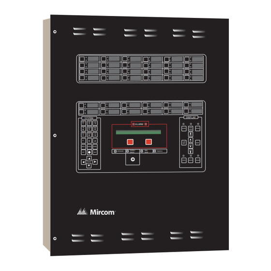
Mircom PRO-2000 Series Operation Manual (128 pages)
Addressable Fire Detection and Control System
Brand:
Mircom
| Category:
Control Systems
| Size: 6 MB
Table of Contents
Table of Contents
3
List of Figures
5
List of Tables
7
PRO-2000 Series
7
The User Interface
8
Figure 1: LCD Display
8
Features Table
9
Table 1: Table of Features
9
Pro-2000, X2 Series - S/E/M
10
PRO-2000 X2S (Standard)
10
PRO-2000 X2E (Expanded)
10
PRO-2000 X2M (MIMIC)
10
PRO-2000 X2, Common Features
10
General Installation Guidelines
11
Special Handling
11
Figure 2: X2, Synoptic Sketch of the PRO-2000, X2 Series
11
Enabling the Onboard Lithium Battery Backup
12
Cable Entry and Internal Routing
12
Figure 3: Lithium Battery Jumper
12
Grounding and Bonding
13
Enclosure Installation
13
Figure 4: X2S, Installation Layout
14
Figure 5: X2E, Installation Layout
15
Figure 6: X2M, Installation Layout
16
Hookup of AC Power and Batteries
17
Alarm Supply
17
AC Power Connection
17
Installing Batteries in the Enclosure
18
Figure 7: Terminal Connections
18
Figure 8: Battery Hookup
19
Pro-2000, X6 Series - S/B/E/M
20
PRO-2000 X6S (Standard)
20
PRO-2000 X6B (Blank)
20
PRO-2000 X6E (Expanded)
20
Pro-2000 X6M (MIMIC)
20
Figure 9: Synoptic Sketch of the PR0-2000, X6 Series
20
PRO-2000 X6 Common Features
21
General Installation Guidelines
21
Special Handling
21
Enabling the Onboard Lithium Battery Backup
21
Cable Entry and Internal Routing
21
Figure 10: Micro-Processor (MPU)
21
Grounding and Bonding
22
Enclosure Installation
22
Figure 11: X6S, Installation Layout
23
Figure 12: X6B, Installation Layout
24
Figure 13: X6E, Installation Layout
25
Figure 14: X6M, Installation Layout
26
Hookup of AC Power and Batteries
27
Alarm Supply
27
Installing Batteries in the Enclosure
27
Figure 15: Battery Hookup
27
PRO-2000 X0 Series - S/E/M
29
General Installation Guidelines
29
Figure 16: Synoptic Sketch of the PRO-2000, X0 Series
29
Special Handling
30
Cable Entry and Internal Routing
30
Grounding and Bonding
30
Enclosure Installation
30
Figure 17: X0S, Installation Layout
31
Figure 18: X0E, Installation Layout
32
Figure 19: X0M, Installation Layout
33
Figure 20: X0S, Installation Layout with Power Supply and Batteries
34
Figure 21: X0E, Installation Layout with Power Supply and Batteries
35
Figure 22: X0M Installation Layout with Power Supply and Batteries
36
PRO-2000 Multi-Panel Systems
37
Figure 23: PRO-2000 Networked Panels
37
Figure 24: X2 and X6 Network Wiring to a Repeater, X0
38
Figure 25: Networking the X2 and X6 Using the Communication Card
39
Main Processing Cards
40
MPU - Main Processing Unit Card
40
Figure 26: MPU (Main Processing Unit) Card
40
Figure 27: MPU Backplane Connectors
41
Table 2: MPU Pinouts
42
Table 3: MPU Relays
42
Table 4: MPU Switches
42
Table 5: MPU Jumpers
43
Table 6: MPU Leds
43
LCD - Liquid Crystal Display Card
44
Figure 28: LCD Card
44
Figure 29: LCD Backplane Connectors
44
X6 and X0 Series
45
Figure 30: Expansion Card and LCD Backplane
46
Table 7: LCD Pinouts
47
Table 8: LCD Relays
47
Table 9: LCD Switches
47
Table 10: LCD Jumpers
48
Table 11: LCD Leds
48
Expansion Cards
49
Communication Card
50
Figure 31: Communication Card Connections
50
Table 12: Communication Card Pin Outs
50
Table 13: Communication Card Leds
50
Figure 32: Communication Card Wiring - Loop/Stub Mode
51
APS-14127-00 Auxiliary Power Supply
52
Figure 33: APS-14127-00 Auxiliary Power Supply
52
Figure 34: APS-14127-00 Auxiliary Power Supply Connector
53
Figure 35: APS-14127-00 Auxiliary Power Supply Typical Connection
53
Figure 36: APS-14127-00 Auxiliary Power Supply LED Indicators
54
12 Zone Supervised OUTPUT Card
55
Figure 37: 12 Zone Supervised Output Card
55
Table 14: 12 Zone Supervised OUTPUT Card Pin Outs - Screw Termination
55
Table 15: 12 Zone Supervised OUTPUT Card Pin Outs - DSUB Termination
56
Table 16: External Power Supply Connections
56
Table 17: 12 Zone Supervised OUTPUT Card Jumpers
56
Table 18: 12 Zone Supervised OUTPUT Card Leds
56
Figure 38: Supervised Output Wiring
57
24/32 Zone Supervised Input Card
58
Figure 39: 24/32 Zone Supervised Input Card
58
Table 19: 24 Zone Supervised Input Card Pin Outs
58
Table 20: 32 Zone Supervised Input Card Pin Outs
59
Table 21: Supervised Input Card Leds
59
Figure 40: Supervised Input Wiring
60
ADI - Addressable Device Interface Card
61
Figure 41: ADI - Addressable Device Interface Card and Connections
61
Figure 42: ADI Driver Module
61
Table 22: ADI Card Pin Outs
62
Table 23: ADI Card Jumpers
62
Table 24: ADI Card Leds
62
Figure 43: ADI Card Wiring - Stub and Loop Mode
63
Figure 44: ADI Card Wiring - Supervised Relay Outputs
64
MIMIC Driver Module
65
Figure 45: MIMIC Driver Module and Connections
65
Table 25: MIMIC Driver Module Leds
65
LCD Expander Card
66
Figure 46: LCD Expander Card and Connections
66
Table 26: MIMIC Driver Module Leds
66
Table 27: LCD Expander Leds
66
External Devices
67
Figure 47: 2 Wire Class B Initiating Circuit Configuration of Monitor Module
68
Figure 48: 2 Wire Style B Initiating Circuit Configuration of Monitor Module
69
Figure 49: Class B Indicating Circuit Wiring of Control Module
70
Figure 50: Typical Isolator Module Wiring - Using EOL Relay for Line Supervision
71
Figure 51: ADI CARD - Typical Wiring Diagram Number 1 for Control Module in Release Configuration
73
Figure 52: ADI CARD - Typical Wiring Diagram Number 2 for Control Module in Release Configuration
74
Figure 53: si Card Typical Wiring Diagram for Releasing Circuit
75
Figure 54: so Card Typical Wiring Diagram for Releasing Circuit
76
Operating Instructions
77
The LCD Panel
77
Figure 55: LCD Panel
77
Table 28: System Status
78
Display
79
Table 29: Indicators and Push Buttons from Display Panel
79
Operating Conditions
80
Table 30: PRO-2000 - Device ID
82
Table 31: MIMIC Driver Module Leds
92
Table 32A: Device Trouble
94
Table 32B: Device Trouble (Continuation)
95
Table 33A: Card Trouble
96
Table 33B: Card Trouble (Continuation)
97
Table 33C: Card Trouble (Continuation)
98
Appendix A - Battery Calculations
99
Table 34: Battery Capacity - Panel Specific Configuration
99
Table 35: X2 Panel Standby Current Consumption - Main Power Supply
100
Table 36: X2 Panel Standby Current Consumption - Battery Back-Up
101
Table 37: X2 Panel Alarm Current Consumption - Battery Back-Up
102
Table 38: X6 Panel Standby Current Consumption - Main Power Supply
103
Table 39: X6 Panel Standby Current Consumption - Battery Back-Up
104
Table 40: X6 Panel Alarm Current Consumption - Battery Back-Up
105
Table 41: System Components Current Consumption - External Power Supply
106
Appendix B - Compatible Devices
107
Warranty & Warning Information
122
Advertisement
Advertisement
Related Products
Mircom Fire-Link PPC-600
Mircom Categories
Control Panel
Intercom System
Fire Alarms
Controller
Smoke Alarm
More Mircom Manuals
Login
Sign In
OR
Sign in with Facebook
Sign in with Google
Upload manual
Upload from disk
Upload from URL