Table of Contents
Advertisement
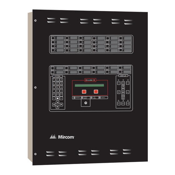
PRO-2000 Series
Addressable Fire Detection and Control System
Installation and Operation Manual
SYSTEM
ABC
DEF
GHI
1
2
3
ALARM
JKL
MNO
PQR
4
5
6
STU
VWX
YZ
8
9
7
*
0
#
CONTINUE
ENTER
MENU
CONTROLS
PANEL
SUPERVISORY
FAILED
EXIT
HELP
ENABLED
DISP LAY
SUPER-
ALARM
TROUBLE
VISORY
FIRST
PREV
LAMP
MORE
TEST
NEXT
LAST
POWER ON
STATUS
ISOLATE
SERVICE
LT-1012 Rev 4.1
Feburary 2016
Advertisement
Table of Contents

Subscribe to Our Youtube Channel
Summary of Contents for Mircom PRO-2000 Series
- Page 1 PRO-2000 Series Addressable Fire Detection and Control System DISP LAY SYSTEM ALARM SUPER- ALARM TROUBLE VISORY FIRST PREV LAMP MORE TEST NEXT CONTINUE ENTER MENU LAST CONTROLS PANEL POWER ON SUPERVISORY FAILED EXIT HELP ENABLED STATUS ISOLATE SERVICE LT-1012 Rev 4.1...
-
Page 3: Table Of Contents
PRO-2000 Installation and Operation Manual Table of Contents List of Figures .......................... iii List of Tables ..........................iv PRO-2000 Series ........................1 The User Interface ........................ 2 Features Table........................3 PRO-2000, X2 SERIES - S/E/M ....................4 PRO-2000 X2S (Standard) ....................4 PRO-2000 X2E (Expanded) .................... - Page 4 Table of Contents LCD Expander Card......................60 External Devices ........................61 OPERATING INSTRUCTIONS ....................71 The LCD Panel........................71 DISPLAY ..........................73 Operating Conditions......................74 Appendix A - Battery Calculations ..................93 Appendix B - Compatible Devices ..................101 Warranty & Warning Information ................... 116...
-
Page 5: List Of Figures
PRO-2000 Installation and Operation Manual List of Figures Figure 1: LCD Display ........................... 2 Figure 2: X2, Synoptic sketch of the PRO-2000, X2 series................5 Figure 3: Lithium Battery Jumper ........................6 Figure 4: X2S, Installation Layout........................8 Figure 5: X2E, Installation Layout........................9 Figure 6: X2M, Installation Layout ......................... - Page 6 PRO-2000 Installation and Operation Manual List of Tables Table 1: Table of features ........................3 Table 2: MPU Pinouts .......................... 36 Table 3: MPU Relays ........................... 36 Table 4: MPU Switches ........................36 Table 5: MPU Jumpers ......................... 37 Table 6: MPU LEDs ..........................37 Table 7: LCD Pinouts ...........................
-
Page 7: Pro-2000 Series
PRO-2000 Installation and Operation Manual PRO-2000 Series The PRO-2000 is a sophisticated micro-processor-based, fire detection, monitoring and control series of panels. The panels are fully on-site configurable. The number and type of PRO-2000 panels depend on your application. They come in different versions-an X2, X6, and X0-allowing system scalability. -
Page 8: The User Interface
PRO-2000 Series The User Interface Mounted on the enclosure door, the LCD Display provides the user interface for the PRO-2000. The LCD Display comprises an LCD card, a display/control escutcheon with configurable LEDs and push buttons, control key switch, and a buzzer. -
Page 9: Features Table
PRO-2000 Installation and Operation Manual Features Table USCG Feature X2S X2E X2M X6S X6E X6M X6B X0S X0E X0M Listing Up to 1200 local detection/control devices/zones per panel Up to 3600 local detection/control devices/zones per panel Up to 5000 networked detection/control zones per panel Up to 10000 networked detection/control zones per panel... -
Page 10: Pro-2000, X2 Series - S/E/M
PRO-2000, X2 SERIES - S/E/M PRO-2000, X2 SERIES - S/E/M The PRO-2000 X2 Series are fire alarm monitoring and control units suitable for small to medium applications. Large applications can be covered with networked panels. The PRO-2000 X2 Series consists of three types of panels: the X2S, the X2E, and the X2M. PRO-2000 X2S (Standard) The X2S is the standard panel housed in a 23”... -
Page 11: General Installation Guidelines
PRO-2000 Installation and Operation Manual Geographic MIMIC Power-Limited Circuit (MIMIC driver) LCD expander Networking Detection and Expansion cards (RS-422) Signaling (Up to 2) RS-422 Circuits Processing and Module Display Unit Communications (LCD) Backplane Printer (RS-232) Master Alarm and Fault Relays RS-232 Module Power supply... -
Page 12: Enabling The Onboard Lithium Battery Backup
PRO-2000, X2 SERIES - S/E/M Enabling the Onboard Lithium Battery Backup The X2 panels are shipped with the jumper for the lithium battery disconnected. You must insert the jumper to activate the battery backup for the real time clock and the RAM memory used for the event log. Jumper is located on the LCD (JP6). -
Page 13: Grounding And Bonding
PRO-2000 Installation and Operation Manual • Centre-to-centre spacing between an entry hole for Power-Limited circuit cables and an entry hole for Non- Power-Limited circuit cables must not be less than two (2) times the diameter of the larger entry hole. •... -
Page 14: Figure 4: X2S, Installation Layout
PRO-2000, X2 SERIES - S/E/M 29.68" [753.92mm] 90° 46.76" [1187.60mm] 23.10" [586.74mm] 7.16" [181.94mm] 1.20" [30.48mm] 21.00" [533.40mm] 0.90" [22.86mm] 24.00" [609.60mm] 22.20" [563.88mm] Figure 4: X2S, Installation Layout... -
Page 15: Figure 5: X2E, Installation Layout
PRO-2000 Installation and Operation Manual 29.68" [753.92mm] 90.00° 46.76" [1187.60mm] 23.10" [586.74mm] 21.00" [533.40mm] 1.20" [30.48mm] 7.16" [181.97mm] 0.90" [22.86mm] 30.00" [762.00mm] 28.20" [716.28mm] MODEL NO: PART NO: SERIAL NO: INPUT VOLTAGE: V.AC INPUT FREQUENCY: FUSE RATING: AMPS POWER LIMITED: OUTPUT Figure 5: X2E, Installation Layout... -
Page 16: Figure 6: X2M, Installation Layout
PRO-2000, X2 SERIES - S/E/M 29.68" [753.92mm] 90.00° 46.76" [1187.60mm] 23.10" [586.74mm] 21.00" [533.40mm] 0.90" [22.86mm] 7.16" [181.97mm] 1.20" [30.48mm] 41.00" [1041.40mm] 39.20" [995.68mm] Figure 6: X2M, Installation Layout... -
Page 17: Hookup Of Ac Power And Batteries
PRO-2000 Installation and Operation Manual Hookup of AC Power and Batteries The Power Supply provides a regulated 28 VDC to the PRO-2000 series and provides charge current to the optional backup batteries. As the batteries are kept permanently charged, power is continuously provided (Uninterruptible Power Supply or UPS). -
Page 18: Installing Batteries In The Enclosure
PRO-2000, X2 SERIES - S/E/M GROUND STUD GROUND NON POWER NEUTRAL LIMITED CIRCUIT LINE FUSE Figure 7: Terminal Connections Installing Batteries in the Enclosure The following instructions apply only to systems requiring 42 Amp-Hours or less of battery back-up capacity. 1. -
Page 19: Figure 8: Battery Hookup
PRO-2000 Installation and Operation Manual... -
Page 20: Pro-2000, X6 Series - S/B/E/M
PRO-2000, X6 SERIES - S/B/E/M PRO-2000, X6 SERIES - S/B/E/M The PRO-2000 X6 panels are fire alarm monitoring and control units suitable for medium to large applications. Very large applications can be covered with networked panels. The PRO-2000 X6 Series consist of four types of panels: the X6B, the X6E, the X6M and the X6S. PRO-2000 X6S (standard) The X6S is the standard panel housed in a 24"... -
Page 21: Pro-2000 X6 Common Features
PRO-2000 Installation and Operation Manual PRO-2000 X6 Common Features The X6 Series supports communication and networking functions. The X6 can operate as a stand-alone panel or it can be networked in a master/slave configuration. The master can be configured to monitor and control the slave panels as well as monitor its own devices. -
Page 22: Grounding And Bonding
PRO-2000, X6 SERIES - S/B/E/M Cable entry holes must be punched in accordance with the following criteria: • Separate holes are required for the entry of Power-Limited and Non-Power-Limited circuit cables. • Centre-to-centre spacing between an entry hole for Power-Limited circuit cables and an entry hole for Non- Power-Limited circuit cables must not be less than two (2) times the diameter of the larger entry hole. -
Page 23: Figure 11: X6S, Installation Layout
PRO-2000 Installation and Operation Manual 29.68" [753.92mm] 90° 46.76" [1187.60mm] 23.10" [586.74mm] 1.20" [30.48mm] 21.00" [533.40mm] 0.90" [22.86mm] 7.16" [181.97mm] 30.00" [762.00mm] 28.20" [716.28mm] Figure 11: X6S, Installation Layout... -
Page 24: Figure 12: X6B, Installation Layout
PRO-2000, X6 SERIES - S/B/E/M 29.68" [753.92mm] 90° 46.76" [1187.60mm] 23.10" [586.74mm] 1.20" [30.48mm] 21.00" [533.40mm] 0.90" [22.86mm] 7.16" [181.97mm] 28.20" [716.28mm] 30.00" [762.00mm] Figure 12: X6B, Installation Layout... -
Page 25: Figure 13: X6E, Installation Layout
PRO-2000 Installation and Operation Manual 29.68" [753.92mm] 90° 46.76" [1187.60mm] 23.10" [586.74mm] 21.00" [533.40mm] 0.90" [22.86mm] 7.16" [181.97mm] 1.20" [30.48mm] 28.20" [716.28mm] 30.00" [762.00mm] Figure 13: X6E, Installation Layout... -
Page 26: Figure 14: X6M, Installation Layout
PRO-2000, X6 SERIES - S/B/E/M 29.68" [753.92mm] 90° 46.76" [1187.60mm] 23.10" [586.74mm] 7.16" [181.97mm] 21.00" [533.40mm] 0.90" [22.86mm] 1.20" [30.48mm] 39.20" [995.68mm] 41.00" [1041.40mm] Figure 14: X6M, Installation Layout... -
Page 27: Hookup Of Ac Power And Batteries
Hookup of AC Power and Batteries The Power Supply provides a regulated 28 VDC to the PRO-2000 series and provides charge current to the optional backup batteries. As the batteries are kept permanently charged, power is continuously provided (Uninterruptible Power Supply or UPS). - Page 28 PRO-2000, X6 SERIES - S/B/E/M...
-
Page 29: Pro-2000 X0 Series - S/E/M
PRO-2000 Installation and Operation Manual PRO-2000 X0 Series - S/E/M The PRO-2000 X0 Series are remote annunciator panels for the X2 and X6 Series. The PRO-2000 X0 Series consist of three types of panels: the X0S, the X0E, and the X0M. PRO-2000 X0S (Standard) Power-limited circuits The X0S is the standard panel... -
Page 30: Special Handling
PRO-2000 X0 Series - S/E/M Special Handling Circuit cards are to be stored in anti-static packaging and kept away from the sun and from direct sources of intense UV light. The circuit card may be subject to degradation due to electrostatic discharge; therefore grounding straps must be worn when handling the cards. -
Page 31: Figure 17: X0S, Installation Layout
PRO-2000 Installation and Operation Manual 29.68" [753.92mm] 90° 46.76" [1187.60mm] 23.10" [586.74mm] 21.00" [533.40mm] 0.90" [22.86mm] 7.16" [181.97mm] 1.20" [30.48mm] 24.00" [609.60mm] 22.20" [563.88mm] Figure 17: X0S, Installation Layout... -
Page 32: Figure 18: X0E, Installation Layout
PRO-2000 X0 Series - S/E/M 29.68" [753.92mm] 90° 46.76" [1187.60mm] 23.10" [586.74mm] 0.90" [22.86mm] 21.00" [533.40mm] 7.16" [181.97mm] 1.20" [30.48mm] 30.00" [762.00mm] 28.20" [716.28mm] Figure 18: X0E, Installation layout... -
Page 33: Figure 19: X0M, Installation Layout
PRO-2000 Installation and Operation Manual 29.68" [753.92mm] 90° 46.76" [1187.60mm] 23.10" [586.74mm] 7.16" [181.97mm] 0.90" [22.86mm] 21.00" [533.40mm] 1.20" [30.48mm] 41.00" [1041.40mm] 39.20" [995.68mm] Figure 19: X0M, Installation Layout... -
Page 34: Figure 20: X0S, Installation Layout With Power Supply And Batteries
PRO-2000 X0 Series - S/E/M 29.68" [753.92mm] 90° 46.76" [1187.60mm] 7.16" [181.94mm] 23.10" [586.74mm] 1.20" [30.48mm] 21.00" [533.40mm] 0.90" [22.86mm] 24.00" [609.60mm] 22.20" [563.88mm] Figure 20: X0S, Installation Layout with Power Supply and Batteries... -
Page 35: Figure 21: X0E, Installation Layout With Power Supply And Batteries
PRO-2000 Installation and Operation Manual 29.68" [753.92mm] 90.00° 46.76" [1187.60mm] 23.10" [586.74mm] 21.00" [533.40mm] 7.16" [181.97mm] 0.90" [22.86mm] 1.20" [30.48mm] 28.20" [716.28mm] 30.00" [762.00mm] Figure 21: X0E, Installation Layout with Power Supply and Batteries... -
Page 36: Figure 22: X0M Installation Layout With Power Supply And Batteries
PRO-2000 X0 Series - S/E/M 29.68" [753.92mm] 90.00° 46.76" [1187.60mm] 23.10" [586.74mm] 21.00" [533.40mm] 0.90" [22.86mm] 7.16" [181.97mm] 1.20" [30.48mm] 39.20" [995.68mm] 41.00" [1041.40mm] Figure 22: X0M Installation Layout with Power Supply and Batteries... -
Page 37: Pro-2000 Multi-Panel Systems
PRO-2000 Installation and Operation Manual PRO-2000 Multi-Panel Systems PRO-2000 panels can be programmed to act as Master or Slave panels. A Master panel monitors and controls a system comprising several Slave panels. Up to 32 PRO-2000 Slave panels can be connected, in an open or closed loop configuration, to the master panel by means of a 4-conductor, full duplex, serial communication data link. -
Page 38: Figure 24: X2 And X6 Network Wiring To A Repeater, X0
PRO-2000 Multi-Panel Systems... -
Page 39: Figure 25: Networking The X2 And X6 Using The Communication Card
PRO-2000 Installation and Operation Manual ALL CIRCUITS ARE POWER-LIMITED AND SUPERVISED X6/X2 PANEL X2 PANEL COMM CARD TX1+ TX1- RX1- RX1+ TX1- RX1+ TX1+ RX1- RX2- RX2+ TX2- TX2+ TX2+ TX2- SLAVE PANEL #1 RX2+ RX2- X2 PANEL MASTER PANEL TX1+ TX1- Omit these wires... -
Page 40: Main Processing Cards
MAIN PROCESSING CARDS MAIN PROCESSING CARDS There are two main processing cards, the MPU and the LCD. These cards form the basis for the PRO-2000 Panels' electronics. In the X6 panels, the MPU card with the MPU Backplane, expansion cards (optional), Power Supply and Transformer are mounted to a removable mounting plate in the enclosure base. -
Page 41: Figure 27: Mpu Backplane Connectors
PRO-2000 Installation and Operation Manual Jumpers RS-232 Master Alarm LCD Display LCD Display Rotary Switch Phone Jack and Trouble RS-422 Link RS-422 Link Relays DIP Switches Lithium Battery Reset Button Reset Status Running RS-232 RS-422 Error code Communication Indicators LD11 Program Device module sockets... -
Page 42: Table 2: Mpu Pinouts
MAIN PROCESSING CARDS When a system is first delivered the MPU card has its internal battery jumper, JP3, disabled. Prior to installation, move the jumper shunt (located above the board mounted battery) into position over both pins. If the jumper is missing, the panel will annunciate a "Clock Battery Fault “... -
Page 43: Table 5: Mpu Jumpers
PRO-2000 Installation and Operation Manual Jumper Function Position Watchdog Enable Installed Watchdog one-shot mode Installed Lithium Battery Enable Installed on site Non installed when 128K x 8 RAM chips are used. RAM Size Selection Installed when 512K X 8 RAM chips are used. Table 5: MPU Jumpers Function Definition... -
Page 44: Lcd - Liquid Crystal Display Card
MAIN PROCESSING CARDS LCD - Liquid Crystal Display card The LCD implements the user interface to the PRO-2000 panels using LEDs and a 2-line x 40-character LCD unit. Figure 28: LCD Card REAR VIEW LCD Expansion Mimic or Master Alarm Backplane LCD Expansion and Trouble... -
Page 45: X6 And X0 Series
PRO-2000 Installation and Operation Manual X6 and X0 series The LCD performs only display functions. X2 Series • The LCD performs processing and display functions. • The LCD Backplane is used to provide connectivity between the LCD and the interface cards. Up to 2 expansion cards can be connected to the LCD Backplane. -
Page 46: Figure 30: Expansion Card And Lcd Backplane
MAIN PROCESSING CARDS EXPANSION CARD LCD BACKPLANE Figure 30: Expansion Card and LCD Backplane... -
Page 47: Table 7: Lcd Pinouts
PRO-2000 Installation and Operation Manual RS-232 Modular Phone Jack COMM Loop (S1 (J6) X) COMM Loop (S2 (J8) Y) (J19) Signal Signal Signal TX1+ (out) TX2+ (out) TX (out) TX1- (out) TX2- (out) RX (in) RTS* (out) CTS* (in) RX1+ (in) RX2+ (in) CD* (in) RX1- (in) -
Page 48: Table 10: Lcd Jumpers
MAIN PROCESSING CARDS Jumper Function Position Watchdog enable Installed Watchdog one-shot mode Installed Lithium Battery enable Installed on site - Non installed when 128 K x 8 RAM chips are used. JP2, JP3 RAM size function - Installed when 512 K x 8 RAM chips are used. Table 10: LCD Jumpers Function Definition... -
Page 49: Expansion Cards
There are several types of expansion cards that can be added to the PRO-2000 Series panels. These are: • Addressable Detector Interface (ADI) card - smoke/heat detectors, monitor modules, control modules, and 4 onboard supervised/unsupervised outputs •... -
Page 50: Communication Card
MAIN PROCESSING CARDS Communication Card Field Wiring RS-422 RS-422 or RS-232 Sockets Connector to MPU or LCD Field Wiring RS-232 Power Indicators Metalized Ground LD12 Figure 31: Communication Card Connections The Communication card enables the PRO-2000 panels to be connected to various communication interfaces such as RS-232, and RS-422. -
Page 51: Figure 32: Communication Card Wiring - Loop/Stub Mode
PRO-2000 Installation and Operation Manual... -
Page 52: Aps-14127-00 Auxiliary Power Supply
MAIN PROCESSING CARDS APS-14127-00 Auxiliary Power Supply The APS-14127-00 auxiliary power supply provides two power limited outputs, each rated at 28VDC and 2A. Both out- puts can be used simultaneously and the total current available from the power supply is 2.5A in standby condition and 4A in alarm. -
Page 53: Figure 34: Aps-14127-00 Auxiliary Power Supply Connector
PRO-2000 Installation and Operation Manual Figure 34: APS-14127-00 Auxiliary Power Supply Connector Typical connection for APS-14127-00 auxiliary power supply is shown in next figure. In this scheme, s single monitor module is used for picking up trouble information from the auxiliary supply. If individual trouble reporting is required, use a single monitor module per trouble contact. -
Page 54: Figure 36: Aps-14127-00 Auxiliary Power Supply Led Indicators
MAIN PROCESSING CARDS Trouble tracing information is provided by the 14043 control interface situated in upper left corner of the APS-14127-00 auxiliary power supply enclosure. Figure 36: APS-14127-00 Auxiliary Power Supply LED Indicators... -
Page 55: 12 Zone Supervised Output Card
PRO-2000 Installation and Operation Manual 12 Zone Supervised OUTPUT Card Power Indicators Power Supply External Output Status Connector to Indicator MPU or LCD Relays LD17 JP25 Metalized Ground Screw Connectors for Field Connections Power Indicators Power Supply External Output Status Indicator Connector to SUBD Connector... -
Page 56: Table 15: 12 Zone Supervised Output Card Pin Outs - Dsub Termination
MAIN PROCESSING CARDS Signal Connection Signal Connection Signal Connection Signal Connection SO1-NO J5-1 SO4-NO J5-13 SO7-NO J5-25 SO10-NO J5-37 SO1-NC J5-2 SO4-NC J5-14 SO7-NC J5-26 SO10-NC J5-38 SO1-COM J5-3 SO4-COM J5-15 SO7-COM J5-27 SO10-COM J5-39 J5-4 J5-16 J5-28 J5-40 SO2-NO J5-5 SO5-NO J5-17... -
Page 57: Figure 38: Supervised Output Wiring
PRO-2000 Installation and Operation Manual NOTE: 1. MORE THAN ONE RELAY, VALVE OR SOLENOID PER OUTPUT IS NOT ALLOWED. POWER LIMITED, SUPERVISED CIRCUITS SO CARD Note 4 Note 3 ALL CIRCUITS ARE POWER-LIMITED AND SUPERVISED VIN+ VIN- NOTES: Jumper to be installed as per supervision jumper Table 22. -
Page 58: 24/32 Zone Supervised Input Card
MAIN PROCESSING CARDS 24/32 Zone Supervised Input Card Power indicators Connector to 24 inputs MPU or LCD Metalized ground Supervised inputs 1 to 12 Supervised inputs 13 to 24 Flat ribbon cable Screw connectors for field connections 64 pin connection Power indicators Screw terminals... -
Page 59: Table 20: 32 Zone Supervised Input Card Pin Outs
PRO-2000 Installation and Operation Manual The adapter's supervised input # is indicated near the screw connections. The + and - signs on the adapter indicate the polarity of the connection. Signal Connection Signal Connection Signal Connection Signal Connection SI1+ J4-A32 SI9+ J4-A24 SI17+... -
Page 60: Figure 40: Supervised Input Wiring
MAIN PROCESSING CARDS LEGEND: IONIZATION SMOKE DETECTOR HEAT DETECTOR MANUAL FIRE ALARM BOX To SI Card SI1+ EOL 6.8K ohms SI1- Note 3 TYPICAL ZONE WIRING POWER LIMITED CIRCUIT NOTES: Circuits are power limited and supervised -Maximum circuit current: 28 mA -Voltage range: 19 - 25.5VDC -Maximum cable resistance: 50 ohms See Appendix B for PRO-2000 compatible input... -
Page 61: Adi - Addressable Device Interface Card
PRO-2000 Installation and Operation Manual ADI - Addressable Device Interface card Figure 41: ADI - Addressable Device Interface Card and Connections The ADI card supports up to two loops (complying with the operation and supervision requirements of NFPA Signalling Line Circuit Style 6) of detectors or up to four stubs (complying with NFPA SLC Style 4 requirements). You can have up to 99 detectors and 99 modules on each loop or stub for a total monitoring capacity of 600 devices - limited by memory. -
Page 62: Table 22: Adi Card Pin Outs
MAIN PROCESSING CARDS Signal Connection Signal Connection Signal Connection J7-1 J7-11 LPY+ (loop2) S4 J6-1 J7-2 COM4 J7-12 LPY- (loop2) S4 J6-2 COM1 J7-3 VIN+ J7-13 LPX+ (loop2) S3 J6-3 J7-4 VIN- J7-14 LPX- (loop2) S3 J6-4 J7-5 Vout+ J7-15 COM2 J7-6 Vout-... -
Page 63: Figure 43: Adi Card Wiring - Stub And Loop Mode
PRO-2000 Installation and Operation Manual Minimum detected ground fault impedance is 1K ohms. -
Page 64: Figure 44: Adi Card Wiring - Supervised Relay Outputs
MAIN PROCESSING CARDS Minimum detected ground fault impedance is 1K ohms. -
Page 65: Mimic Driver Module
PRO-2000 Installation and Operation Manual MIMIC Driver Module The MIMIC Driver Module drives the LEDs on the MIMIC displays for the X0M, X2M, and X6M panels. The LCD card controls the MIMIC Driver module. Each MIMIC Driver module supports up to 48 LEDs and 24 push buttons via two connectors. -
Page 66: Lcd Expander Card
MAIN PROCESSING CARDS Function Definition LD2 (green) 24V input indicator ON when 24V power is present at J4 LD1 (green) VCC indicator ON when the VCC (5V) regulator is functional Table 26: MIMIC Driver Module LEDs LCD Expander Card Connector to C o n n e c t o r t o 48 LED's cascade out... -
Page 67: External Devices
PRO-2000 Installation and Operation Manual External Devices The information on connection and wiring of sensors and signaling devices to the modules is intended only as a guideline. For full wiring details for a specific system, refer to the system drawings and instructions and to the installation and wiring instructions provided with each device. -
Page 68: Figure 47: 2 Wire Class B Initiating Circuit Configuration Of Monitor Module
MAIN PROCESSING CARDS... -
Page 69: Figure 48: 2 Wire Style B Initiating Circuit Configuration Of Monitor Module
PRO-2000 Installation and Operation Manual... -
Page 70: Figure 49: Class B Indicating Circuit Wiring Of Control Module
MAIN PROCESSING CARDS Control Module The Control module interfaces standard OUTPUT alarm devices with a PRO-2000 panel via the ADI card. You can program the module's unique address using two rotary switches located on the front of the mounting bracket. The module mounts into a 4"... -
Page 71: Figure 50: Typical Isolator Module Wiring - Using Eol Relay For Line Supervision
PRO-2000 Installation and Operation Manual Isolator Module When the addressable detectors and modules are linked to the ADI Card through a communication loop, isolator modules can be used to divide this loop into several segments. The Isolator module is an automatic switch that opens when the line voltage drops below 4 Volts. If a short circuit occurs between any two isolators, both isolators immediately switch to an open circuit state and isolate the Group of detectors/modules between them. - Page 72 Releasing Device Service The PRO-2000 Series panel can act as a releasing unit for zones where different extinguishing agents are used. A typical releasing set-up consists of heat or smoke detectors, a pull station, an Abort station, a set of extinguishant cylinders and audible/visual signaling devices.
-
Page 73: Figure 51: Adi Card - Typical Wiring Diagram Number 1 For Control Module In Release Configuration
Signaling Systems (ULC Listed in Canada) regulated, Min.Load: 0.005A, 24VDC isolated 24VDC power supply (supervised and power limited). Use UL listed (ULC Canada) For Releasing circuits use Special Application Mircom APS-14127-00 Auxiliary Power Supply. UL listed (ULC Canada) EOL relay N.O. contacts (24VDC COIL) Do not use looped wire on terminals 3 and 4. -
Page 74: Figure 52: Adi Card - Typical Wiring Diagram Number 2 For Control Module In Release Configuration
For NAC circuits use UL Listed for Fire Protective Signaling Systems (ULC Listed in Canada) regulated, isolated 24VDC power supply (supervised and power limited). 24VDC For Releasing circuits use Special Application Mircom POWER APS-14127-00 Auxiliary Power Supply. SUPPLY Do not use looped wire on NOTE 4 terminals 3 and 4. -
Page 75: Figure 53: Si Card Typical Wiring Diagram For Releasing Circuit
PRO-2000 Installation and Operation Manual Note 1 Note 4 LEGEND: IONIZATION SMOKE DETECTOR Note 2 Note 3 RELEASE MANUAL SWITCH Note 1 ABORT SWITCH (SELF RESTORING SWITCH) Note 3 Note 1 SI2+ NOTES FOR SUPERVISED INPUT CARD: SI CARD -Maximum cable resistance: 40 ohms SI2- Note 3 -Voltage range: 19-25 VDC. -
Page 76: Figure 54: So Card Typical Wiring Diagram For Releasing Circuit
For NAC circuits use UL Listed for Fire Protective Signaling Systems (ULC Listed in Canada) regulated, isolated 24VDC power supply (supervised and power limited). For Releasing circuits use Special Application Mircom APS-14127-00 Auxiliary Power Supply. For NAC circuits, us MP-300SP when EOL mounting plate is required. -
Page 77: Operating Instructions
PRO-2000 Installation and Operation Manual OPERATING INSTRUCTIONS The LCD Panel The LCD Panel provides the main user interface for the PRO-2000 Series. The front panel divides into four functional areas: SYSTEM STATUS Alarm indicators (also called Dual Alarm indicators), the Liquid Crystal Display, the Reset and Acknowledge push buttons, the Supervisory, Controls Enabled, Panel Failed, Power indicators and the Control Key Switch. -
Page 78: Table 28: System Status
OPERATING INSTRUCTIONS Draws attention that a change of state has occurred. A fast beep indicates an alarm Buzzer condition, and slow beep indicates all other events. The Red indicators illuminate/flash on detection of an alarm condition. Rapid flashing Alarm indicators indicates new alarms, slow flashing indicates cleared alarms, and steady-on to indicate acknowledged alarms. -
Page 79: Display
PRO-2000 Installation and Operation Manual DISPLAY The indicators on the display panel flash as each new event occurs and remain steady-on when acknowledged. Resetting or clearing an event state causes the corresponding LEDs to flash then extinguish. The Red indicator illuminates/flashes on detection of an alarm condition. Rapid flashing Alarm indicator indicates new alarms, slow flashing indicates cleared alarms, and steady-on to indicate acknowledged alarms. -
Page 80: Operating Conditions
Operating Conditions Operating Conditions Five conditions may be identified by the PRO-2000. Four of those are considered Off-Normal. • Normal: Everything is as it should be. • Alarm: triggered when a fire detection or alarm initiating device (e.g. smoke or heat detector, fire alarm station etc.) goes into alarm. - Page 81 PRO-2000 Installation and Operation Manual Press the Acknowledge push button. The condition becomes non-resident and the LCD updates. If this is the last off-normal condition, the message, All Systems Normal displays. Otherwise, the system returns to the dual event modes. When the system registers mixed events, the basic scenario remains the same with one major difference: the system prioritizes events according to specific rules.
-
Page 82: Table 30: Pro-2000 - Device Id
Operating Conditions Device ID Concepts The Device ID is a special code used by the system to identify all the devices connected to the PRO-2000. In certain menus it is required to identify a certain device Group to the system. For example, when placing/removing a device/device Group in/from Service or Isolate modes. - Page 83 PRO-2000 Installation and Operation Manual Entering a Device ID Example The first line of the LCD gives information on how to proceed while the second one is reserved for the Device ID. USE: ←, →, ↑, ↓, to scroll, Enter to select Device ID: NN-NNAN-ANNN.N (Edit +S) The plus sign and the letter S displayed next to Edit refers to the action being taken.
- Page 84 Operating Conditions Operating Procedures - Off-Normal conditions The following procedures apply to the PRO-2000 default configuration. It is designed to offer maximum security. Your system may be configured differently. General Alarm Condition The General Alarm Sequence is applied to each control OUTPUT which has been configured as a General Alarm output. The General Alarm On and Off push buttons can be factory configured to use two of the user-defined buttons.
- Page 85 PRO-2000 Installation and Operation Manual To Acknowledge a Single New Off-Normal Condition • Insert the key into the Control Key switch and turn to activate. The Controls Enabled indicator illuminates. • Depress and release the Acknowledge push button. The following events occur: •...
- Page 86 Operating Conditions Clear the acknowledged alarm. After the alarm condition has been investigated and no hazardous condition has been found, activate the Control Key switch. Depress the Display Alarm push button to access the Alarm Event List. If necessary, use the Navigation arrows to select the alarm to reset.
- Page 87 PRO-2000 Installation and Operation Manual LCD Panel Operations - Menu Mode The buttons on the System Keypad are used mainly for maintenance functions at access level 1 and 2. • The numbers are used to select menu options and used as a generic numeric keypad for operations such as setting the clock.
- Page 88 Operating Conditions Main Menu Use the Control Key switch to activate the panel for level 1 access. Press and release the Menu push button. The following message displays on the LCD, two lines at a time. Use the arrow push buttons to scroll through the Main Menu options. MAIN MENU 1 Event Log 2 Access Level...
- Page 89 PRO-2000 Installation and Operation Manual Whichever option you select from the Display Log menu, the system asks for specification of the time interval. The LCD displays the following: Display events logged in time interval: YYYY:MM:DD HH:MM YYYY:MM:DD HH:MM The YYYY:MM:DD HH:MM references specify the time interval of the logged events to display. Default references correspond to the time of the oldest and of the newest event in the log.
- Page 90 Operating Conditions Main Menu -> Event Log -> Clear Event Log This option requires access level 2. If this option is selected while the system is not set at access level 2, the LCD displays the following message: Permission denied, access level too low PRESS Continue To gain access to level 2, refer to the next section (going to access level 2).
- Page 91 PRO-2000 Installation and Operation Manual Main Menu -> Set Clock Select 3 from the Main Menu. The LCD displays the following message: Current Time: YYYY:MM:DD HH:MM PRESS: Continue to modify or Exit Line 1 indicates the current date and time and line 2 shows the options. Press and release the Continue push button.
-
Page 92: Table 31: Mimic Driver Module Leds
Operating Conditions Main Menu -> Maintenance MAINTENANCE MENU 1 - Service Mode 2 - Isolate Mode EXIT - QUIT Allows verification of the operational state of the PRO-2000 initiating devices (for Service Mode example, smoke detectors). The alarms are normally annunciated at the panel, but not associated outputs are triggered. - Page 93 PRO-2000 Installation and Operation Manual Maintenance Menu - > Service Mode -> Remove Select 2 from the Service Menu. The information entered when placing a device in Service displays on the LCD with the exception of the plus sign which changes to a minus sign (-S, meaning remove from Service). After entering the Device ID, confirm using the Enter push button, to remove the device from service.
-
Page 94: Table 32A: Device Trouble
Operating Conditions Trouble List When a trouble condition is first annunciated, the Display Trouble LED blinks, the panel buzzer starts to sound in a slow tempo and the LCD displays a message describing the Trouble. • Read and acknowledge the trouble message or messages by pressing the Acknowledge push button once for each trouble message. -
Page 95: Table 32B: Device Trouble (Continuation)
PRO-2000 Installation and Operation Manual SI Device Device located at the specified address (refer to device ID) report s a defective analog to digital Bad A/D convertor. Open Circuit An open circuit is detected at the specified address (refer to device ID). Short-Circuit A short-circuit is detected at the specified address (refer to device ID). -
Page 96: Table 33A: Card Trouble
Operating Conditions Card Trouble MPU Card AC Fault No AC power. On a X2 panel, a trouble (short-circuit, etc.) was detected on the power stub X or Y of Power Fault - Stub X or Y the LCD card RS-422 channel. On a X2 panel, a trouble (short-circuit, etc.) was detected on the power to the Mimic Power Fault - Mimics Driver card. -
Page 97: Table 33B: Card Trouble (Continuation)
PRO-2000 Installation and Operation Manual On the LCD located at address #, the back-up batteries have failed a test in which LCD display #, Battery Fault - Long test a load is put on them for a long period of time (10 s). Back-up batteries faulty, change the batteries. -
Page 98: Table 33C: Card Trouble (Continuation)
Operating Conditions SI Card SI card in slot ## missing A SI card is missing in the specified slot. Specified SI card not responding. This fault may be due to hardware or to the SI card in slot ## failed presence of a wrong card in the specified slot. -
Page 99: Appendix A - Battery Calculations
PRO-2000 Installation and Operation Manual Appendix A - Battery Calculations Nominal battery voltage should be 24 VDC. Charging voltage is 2.3V per cell minimum. Initial charging current is 2.14A total. Battery capacity requirements calculations This appendix contains tables used to adequately calculate the battery capacity needed for a specific PRO-2000 panel configuration. -
Page 100: Table 35: X2 Panel Standby Current Consumption - Main Power Supply
Appendix A - Battery Calculations Standby current consumption of PRO-2000, X2 panels Main power supply (28V nominal) Standby Current System Component Total (amps) LCD card (X0) (with RS-422) 0.278 LCD card (X2) 0.251 = 0.251 LCD on board RS-232 module 0.063 LCD card user defined LED (local or X0) 0.0022... -
Page 101: Table 36: X2 Panel Standby Current Consumption - Battery Back-Up
PRO-2000 Installation and Operation Manual Standby current consumption of PRO-2000, X2 panels Battery back-up (24V nominal) Standby Current System Component Total (amps) LCD card (X0) (with RS-422) 0.301 LCD card (X2) 0.274 = 0.274 LCD on board RS-232 module 0.073 LCD card user defined LED (local or X0) 0.0022 LCD expander card (Local or X0) -
Page 102: Table 37: X2 Panel Alarm Current Consumption - Battery Back-Up
Appendix A - Battery Calculations Alarm current consumption of PRO-2000, X2 panels Battery back-up (24V nominal) System Component Alarm Current (amps) Total LCD card (X0) (with RS-422) 0.301 LCD card (X2) 0.313 = 0.313 LCD on board RS-232 module 0.073 LCD card user defined LED (local or X0) 0.0022 LCD expander card (Local or X0) -
Page 103: Table 38: X6 Panel Standby Current Consumption - Main Power Supply
PRO-2000 Installation and Operation Manual Standby current consumption of PRO-2000, X6 panels Main power supply (28V nominal) Standby Current System Component Total (amps) MPU card (with RS-422) 0.246 = 0.246 MPU on board RS-232 module 0.063 LCD card (local or X0) (with RS-422) 0.278 = 0.278 LCD card user defined LED (local or X0) -
Page 104: Table 39: X6 Panel Standby Current Consumption - Battery Back-Up
Appendix A - Battery Calculations Standby current consumption of PRO-2000, X6 panels Battery back-up (24V nominal) Standby Current System Component Total (amps) MPU card (with RS-422) 0.273 = 0.273 MPU on board RS-232 module 0.073 LCD card (local or X0) (with RS-422) 0.301 = 0.301 LCD card user defined LED (local or X0) -
Page 105: Table 40: X6 Panel Alarm Current Consumption - Battery Back-Up
PRO-2000 Installation and Operation Manual Alarm current consumption of PRO-2000, X6 panels Battery back-up (24V nominal) System Component Alarm Current (amps) Total MPU card (with RS-422) 0.294 = 0.294 MPU on board RS-232 module 0.073 LCD card (local or X0) (with RS-422) 0.301 = 0.301 LCD card user defined LED (local or X0) -
Page 106: Table 41: System Components Current Consumption - External Power Supply
Appendix A - Battery Calculations Current consumption of PRO-2000 system components, External power supply Current from External power supply System Device (Amps) MPU card (with RS-422) LCD card (X0/X6) (with RS-422) LCD card (X2) LCD card user defined LEDs (current for one LED) LCD expander card LCD expander card LEDs Mimic driver module... -
Page 107: Appendix B - Compatible Devices
Pro-2000 Series UL Listed Compatible Addressable Loop Modules Appendix B - Compatible Devices Pro-2000 Series UL Listed Compatible Addressable Loop Modules Manufacturer & Model Description Mircom MIX-1251 Low-Profile Analog Ionization Smoke Sensor MIX-2251RAP (CLIP Mode) Advanced Protocol Photoelectronic Smoke Sensor... - Page 108 Pro-2000 Series UL Listed Compatible Addressable Loop Modules Manufacturer & Model Description Secutron MRI-1251 Low-Profile Analog Ionization Smoke Sensor MRI-2251/B/T Low-Profile Analog Photoelectronic Smoke Sensor/plus Thermal MRI-2251RAP (CLIP Mode) Advanced Protocol Photoelectronic Smoke Sensor MRI-2251TM Low-Profile Acclimate™ Intelligent Photoelectric Thermal Sensor MRI-7251 Pinnacle™...
- Page 109 Pro-2000 Series UL Listed Compatible Addressable Loop Modules Manufacturer & Model Description System Sensor continued M500DMR1 Multiple Module with 2 Monitor Inputs and 2 Relay Outputs APIM-10 (CLIP Mode) Advanced Protocol Ten Input Monitor Module IM-10 Ten Input Monitor Addressable Module...
- Page 110 Pro-2000 Series UL Listed Compatible Two-Wire Smoke Detectors Pro-2000 Series UL Listed Compatible Two-Wire Smoke Detectors Notes: 1. Whether mixing different models of compatible smoke detectors or using the same model on the same circuit, total standby current of all detectors must not exceed 3 mA.
- Page 111 Pro-2000 Series UL Listed Compatible Two-Wire Smoke Detectors Maximum # of Smoke Detector Manufacturer Compatibility Identifier Rated Standby devices per Model / Base Head / Base Current circuit Hochiki continued SLR-24H/HSC-220R HD-3/HB-72 0.045mA SLR-835/NS6-220 HD-3/HB-3 0.045mA SLR-835/NS4-220 HD-3/HB-3 0.045mA SLR-835/HSC-220R HD-3/HB-72 0.045mA...
- Page 112 Pro-2000 Series UL Listed Compatible Two-Wire Smoke Detectors Maximum # of Smoke Detector Manufacturer Compatibility Identifier Rated Standby devices per Model / Base Head / Base Current circuit System Sensor continued 2451 / B401 A - A 0.12 mA 2451TH / B401 A - A 0.12 mA...
- Page 113 Pro-2000 Series UL Listed Compatible Four-Wire Smoke Detectors Pro-2000 Series UL Listed Compatible Four-Wire Smoke Detectors Maximum # of Manufacturer & Model/Circuit Devices Mircom MIR-545U MIR-545TU Sentrol-ESL 541C 541CXT 709-MV-21 709-24V-21 741U WITH 702U or 702E Base 449AT, 449C, 449CT, 449CRT, 449CST, 449CSTE, 449CSRT, 449CSRH, 449CSST,...
- Page 114 Pro-2000 Series UL Listed Compatible Signalling Devices Pro-2000 Series UL Listed Compatible Signalling Devices System Sensor - SpectrAlert Wheelock continued Wheelock continued P2415 AS-2475C-FW AMT-12/24-R-ULC P2415W AS-24100C-FW AMT-24-LS-VFR-ULC P241575 AH-24-R MB-G6-24-R P241575W AH-24-WP-R MB-G10-24-R P2475 NS-2415W-FR SM-12/24-R P2475W NS-241575W-FR DSM-12/24-R...
- Page 115 Pro-2000 Series ULC Listed Compatible Addressable Loop Modules Pro-2000 Series ULC Listed Compatible Devices Pro-2000 Series ULC Listed Compatible Addressable Loop Modules Manufacturer & Model Description Mircom MIX-1551A Analog Ionization Smoke Sensor MIX-1251A Low-Profile Analog Ionization Smoke Sensor MIX-2251/BA Analog Photoelectronic Smoke Sensor...
- Page 116 Pro-2000 Series ULC Listed Compatible Addressable Loop Modules Manufacturer & Model Description Secutron continued MRI-2251TMA Low-Profile Acclimate™ Intelligent Photoelectric Thermal Sensor MRI-7251A Pinnacle™ Intelligent Laser Smoke Sensor MRI-M500MA Monitor Module (Universal) MRI-M500CHA Addressable Control Module MRI-M500DMAPA (CLIP Advanced Protocol Dual Input Monitor Module...
- Page 117 Pro-2000 Series ULC Listed Compatible Addressable Loop Modules Manufacturer & Model Description System Sensor continued APCR-6A (CLIP Mode) Advanced Protocol Six Relay Control Module CR-6A Six Relay Control Module SC-6A Six Supervised Control Module BEAM200A Intelligent Addressable Beam Detector BEAM200SA...
- Page 118 Pro-2000 Series ULC Listed Compatible Hardwire Smoke Detectors Pro-2000 Series ULC Listed Compatible Hardwire Smoke Detectors Notes: Whether mixing different models of compatible smoke detectors or using the same model on the same circuit, total standby current of all detectors must not exceed 3 mA.
- Page 119 Pro-2000 Series ULC Listed Compatible Hardwire Smoke Detectors Maximum # of Maximum # of Manufacturer & Model Devices/ Manufacturer & Model Devices/ Circuit Circuit Hochiki continued System Sensor continued SLR-24/NS4-220 1451DH/DH400A SLR-24/HSC-220R 2451-A/DH400A SLR-24H/NS6-220 1151A SLR-24H/NS4-220 2151A SLR-24H/HSC-220R C2W-BA/C2WT-BA SLR-835/NS6-220...
- Page 120 Pro-2000 Series Compatible Synchronized Modules and Strobes Pro-2000 Series Compatible Synchronized Modules and Strobes Notes: 1. * Strobes and horns must be connected to separate circuits since the horn is a non-synchronized audible appliance. 2. Do not mix and match sync module with strobes from different manufacturers because each manufacturer uses different synchronization protocols.
- Page 121 Pro-2000 Fire Panel Maximum Number of Horn/Strobes Pro-2000 Fire Panel Maximum Number of Horn/Strobes Maximum # of Manufacturer Horn/Strobes Wheelock NS-24MCW-FW Gentex MRA-HS3-24 System Sensor P1224 MC Mircom FHS-240-110 Faraday 6234 Series...
-
Page 122: Warranty & Warning Information
Warranty & Warning Information Warranty & Warning Information Warning Please Read Carefully Note to End Users: This equipment is subject to terms and conditions of sale as follows: Note to Installers This warning contains vital information. As the only individual in contact with system users, it is your responsibility to bring each item in this warning to the attention of the users of this system. - Page 123 Mircom shall not be liable for any delays, breakdowns, interruptions, loss, destruction, alteration or other problems in the use of a product arising our of, or caused by, the software.
- Page 124 NOTE: Unless specific pre-authorization in writing is obtained from Mircom management, no credits will be issued for custom fabricated products or parts or for complete fire alarm system. Mircom will at its sole option, repair or replace parts under warranty. Advance replacements for such items must be purchased.
- Page 125 PRO-2000 Installation and Operation Manual Out of Warranty Repairs Mircom will at its option repair or replace out-of-warranty products which are returned to its factory according to the following conditions. Anyone returning goods to Mircom must first obtain an authorization number. Mircom will not accept any shipment whatsoever for which prior authorization has not been obtained.
- Page 128 CANADA - Main O ce U.S.A TECHNICAL SUPPORT © Mircom 2016 25 Interchange Way 4575 Witmer Industrial Estates North America Printed in Canada Vaughan, ON L4K 5W3 Niagara Falls, NY 14305 Tel: (888) Mircom5 Subject to change without prior notice...
Need help?
Do you have a question about the PRO-2000 Series and is the answer not in the manual?
Questions and answers