Sign In
Upload
Manuals
Brands
Mircom Manuals
Fire Alarms
FX-350 Series
Mircom FX-350 Series Manuals
Manuals and User Guides for Mircom FX-350 Series. We have
5
Mircom FX-350 Series manuals available for free PDF download: Installation And Operation Manual, Programming Manual, User Manual
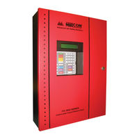
Mircom FX-350 Series Installation And Operation Manual (72 pages)
Analog/Addressable Fire Alarm Panels
Brand:
Mircom
| Category:
Security System
| Size: 6 MB
Table of Contents
Table of Contents
3
1 Industry Canada and FCC Notice
9
Notice for All FX-350 Series Built-In Udacts Sold in Canada
9
Industry Canada Notice
9
Notice for All FX-350 Series Built-In Udacts Sold in the U.S.A
9
FCC Notice
9
2 Introduction
11
Features
11
3 Conventions
13
Circuits
13
Zone/Group
13
Display Points
13
Wiring Styles
13
4 System Components
14
Panel Models
14
Table 1 FX-350 Series Comparison Chart
15
Output Class a Converter: Four Circuits
16
Polarity Reversal/City Tie
16
Remote Annunciator
16
Smart Relay Module
17
RAM-216 Ancillary Annunciator
17
Panel Components and System Accessories
18
Analog/Addressable Devices
18
5 Mechanical Installation
20
Installing the Enclosures
20
Figure 1 Wallbox Dimensions / Mounting the FX-350 - Surface
20
Figure 2 Mounting the FX-350 - Flush
21
Figure 3 Flush Trim Detail
21
Figure 4 Wallbox Dimensions / Mounting the FX-351/FX-353 - Surface /Flush
22
BBX-1024DS and BBX-1024DSR Mechanical Installation
23
Figure 5 BBX-1024DS and BBX-1024DSR Installation Instructions and Dimensions
23
6 Installing Adder Modules
24
Figure 6 Installation of Adder Modules
24
Cable and Jumper Connections for Main Board and Adder Modules
25
Figure 7 Main Fire Alarm Board Cable Connectors and Jumper Locations
25
Figure 8 Main Board (3 Loop Model) Cable Connectors and Jumper Locations
26
Connectors and Jumpers on the Main Fire Alarm Board
27
OCAC-304 Output Class a Converter Adder Module
27
Figure 9 OCAC-304 Output Class a Converter Adder Modules
27
Polarity Reversal and City Tie Module (Model PR-300)
28
PR-300 Cable and Jumper Settings
28
RAX-332 Display Adder Module
28
Figure 10 Polarity Reversal and City Tie Module
28
7 Circuits and Devices
29
Addressable/Analog Devices
29
Analog Devices
30
Drift Compensation
30
Auto Test
30
Contact Inputs
30
Contact Outputs
30
8 Field Wiring
31
Main Fire Alarm Board Field Wiring
31
Figure 11 Addressable Loop Wiring - Class B or Style
31
Table 2 Settings Permitted in CAN/ULCS527
31
Loop Isolators
32
Loop Operation
32
Figure 12 Addressable Loop Wiring - Class a or Style 6
32
Table 3 Loop Wiring Table
32
Indicating (Powered Output) Circuits
33
Indicating Circuit Wiring
33
Table 4 Maximum Wiring Distances
33
Dialer Wiring
35
Figure 13 Indicating Circuit - Class B or Style y Wiring
35
Figure 14 Indicating Circuit -Class a or Style Z Wiring
35
Figure 15 Dialer Wiring
36
Polarity Reversal and City Tie Module (PR-300) Wiring
37
Figure 16 Polarity Reversal and City Tie Module Terminal Connection
37
Auxiliary Power Supplies
38
Aux 2 Resettable Auxiliary Power (Supervised, Regulated)
38
Auxiliary Supply (Supervised, Regulated)
38
Unfiltered Supply (Unsupervised, Unregulated)
38
Figure 17 Supervision of Auxiliary Supplies
38
Power Supply Connections
39
Figure 18 Main Power Supply Connections
39
Connecting to a DCS Surguard Receiver
40
Figure 19 Connecting an FX-350 FACP to a DCS Surguard System Receiver
40
9 System Checkout
41
Before Turning the Power "ON
41
Power-Up Procedure
41
10 Troubleshooting
42
11 Indicators, Controls and Operations
43
Figure 20 LCD Display, LED Indicators and Control Buttons
43
Common Indicators
44
Buzzer
44
AC on LED
44
Common Alarm LED
44
Common Supervisory LED
44
Common Trouble LED
44
CPU Fault LED
44
Ground Fault LED
44
System Reset LED
44
Signal Silence LED
45
Fire Drill LED
45
ALM/SUP/TBL/BLDG AUDIBLE SIL LED (Buzzer Silence)
45
AUTOMATIC ALARM SIGNAL CANCEL LED (Acknowledge)
45
General Alarm LED
45
Lamp Test LED
45
Battery/Charger Trouble LED
45
Leds 1 to 32 for FX-351 and FX-353 Series Only
45
RAX-332 Leds 33 to 64 for FX-351 and FX-353 Series Only
45
Common Controls
46
LCD Display
46
Cursor Buttons
46
Enter Button
46
Cancel Button
46
Menu Button
46
Info Button
46
Signal Silence Button
46
Fire Drill Button
46
General Alarm Button
46
System Reset Button
47
AUTOMATIC ALARM SIGNAL CANCEL Button (Two Stage or PAS Only)
47
Lamp Test Button
47
Single Stage Operation
47
Two-Stage Operation
48
Positive Alarm Sequence
49
Enabling or Disabling the Positive Alarm Sequence
50
Input Types
50
Table 5 Input Types
52
Output Types
53
Evacuation Codes
53
Table 6 Output Types
53
Initial Power-Up Sequence
54
Figure 21 Evacuation and Alert Codes
54
Status Display Mode
55
Queue Display Mode
56
12 Remote Annunciator Operation
57
Conventional Annunciators (RA-1000 Series)
57
Supervision
57
Shared Display Annunciator (RAM-300LCD)
57
13 Dialer Operation
58
Event Reporting
58
Telephone Line Supervision
58
14 Appendix A: Compatible Receivers
59
Table 7 Ademco Contact-ID - FX-350 Series Event Codes
60
15 Appendix B: Reporting
60
Table 8 Security Industries Association SIA-DCS - FX-350 Series Event Codes
61
Table 9 FX-350 Series Specifications
62
16 Appendix C: Specifications
62
Table 10 FX-350 System Modules and Annunciators
63
17 Appendix D: Power Supply and Battery Calculations
64
Table 11 FX-350 Batteries
65
Warranty & Warning Information
66
Advertisement
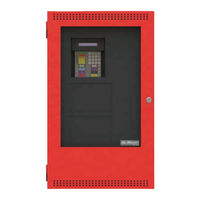
Mircom FX-350 Series Installation And Operation Manual (60 pages)
Analog/Addressable Fire Alarm Panels
Brand:
Mircom
| Category:
Fire Alarms
| Size: 2 MB
Table of Contents
Table of Contents
3
Industry Canada and FCC Notice
7
Introduction
8
Features
8
Conventions
9
Circuits
9
Zone/Group
9
Display Points
9
Wiring Styles
9
System Components
10
Panel Models
10
Output Class a Converter: Four Circuits
11
Polarity Reversal/City Tie
11
Remote Annunciator
12
Smart Relay Module
12
RAM-216 Remote Annunciator
12
Panel Components and System Accessories
13
Analog/Addressable Devices
14
Mechanical Installation
15
Installing the Enclosures
15
Figure 2: Mounting the Fx-350 - Flush
16
Figure 3: Flush Trim Detail
16
Figure 4: Wallbox Dimensions / Mounting the Fx-351/Fx-353 – Surface /Flush
17
Installing Adder Modules
18
Figure 5: Installation of Adder Modules
18
Cable and Jumper Connections for Main Board and Adder Modules
19
Figure 6: Main Fire Alarm Board Cable Connectors and Jumper Locations
19
Figure 7: Main Board (3 Loop Model) Cable Connectors and Jumper Locations
20
Table 1: Connectors and Jumpers on the Main Fire Alarm Board
21
OCAC-304 Output Class a Converter Adder Module
21
Figure 8: Ocac-304 Output Class a Converter Adder Modules
21
Polarity Reversal and City Tie Module (Model PR-300)
22
Figure 9: Polarity Reversal and City Tie Module
22
Table 2: Pr-300 Cable and Jumper Settings
22
RAX-332 Display Adder Module
22
Circuits and Devices
23
Addressable/Analog Devices
23
Analog Devices
23
Contact Inputs
24
Contact Outputs
24
Field Wiring
25
Main Fire Alarm Board Field Wiring
25
Figure 10: Addressable Loop Wiring - Class B or Style
25
Table 3: Loop Wiring Table
25
Loop Isolators
25
Figure 11: Addressable Loop Wiring -Class a or Style
26
Loop Operation
26
Indicating (Powered Output) Circuits
27
Indicating Circuit Wiring
27
Table 4: Indicating Circuit Wiring
27
Figure 12: Indicating Circuit – Class B or Style y Wiring
28
Figure 13: Indicating Circuit –Class a or Style Z Wiring
28
Dialer Wiring
29
Figure 14: Dialer Wiring
29
Polarity Reversal and City Tie Module (PR-300) Wiring
30
Figure 15: Polarity Reversal and City Tie Module Terminal Connection
30
Auxiliary Power Supplies
31
Figure 16: Supervision of Auxiliary Supplies
31
Power Supply Connections
32
Figure 17: Main Power Supply Connections
32
System Checkout
33
Before Turning the Power "ON
33
Power-Up Procedure
33
Troubleshooting
33
Indicators, Controls and Operations
34
Figure 18: Lcd Display, Led Indicators and Control Buttons
34
Common Indicators
35
Common Controls
36
Single Stage Operation
37
Two-Stage Operation
38
Positive Alarm Sequence
39
Enabling or Disabling the Positive Alarm Sequence
39
Input Types
40
Output Types
42
Evacuation Codes
43
Figure 19: Evacuation and Alert Codes
43
Remote Annunciator Operation
46
Dialer Operation
47
Appendix A: Compatible Receivers
47
Appendix B: Reporting
48
Ademco Contact-ID
48
Security Industries Association SIA-DCS
49
Appendix C: Specifications
50
Appendix D: Power Supply and Battery Calculations
51
Warranty & Warning Information
53
Warning Please Read Carefully
53
Limited Warranty
55
Warranty Procedure
55
Disclaimer of Warranties
55
Out of Warranty Repairs
56
Mircom FX-350 Series Programming Manual (48 pages)
Analog/Addressable Fire Alarm Panel
Brand:
Mircom
| Category:
Smoke Alarm
| Size: 0 MB
Table of Contents
Table of Contents
3
System Configuration
5
Panel Configuration
5
Auto Configuration
10
Default Configuration
10
Dialer Configuration
11
Time Configuration
11
After Hours Configuration
11
Configuration
12
Command Mode - Configuration & Operation
14
Menu Operation
14
Configuration Menu
15
Panel Configuration/1. Features
15
Panel Configuration/2. Devices Configuration
19
Panel Configuration/3. Correlation
21
Panel Configuration/4. Groups
22
Panel Configuration/5. Remote Switches
26
Configuration Menu/2. Auto Configuration
26
Configuration Menu/3. Default Configuration
27
Configuration Menu/4. Dialer Configuration
27
Configuration Menu/Dialer Config/1. Account Info
27
Configuration Menu/Dialer Configuration/2. Telephone Line
29
Configuration Menu/Dialer Configuration/3. Report Options
29
Configuration Menu/Dialer Configuration/Report Options/5. Dialer Operation Mode
30
Configuration Menu/Dialer Configuration/4. Time Parameters
30
Configuration Menu/Dialer Configuration/Time Parameter/1. AC Loss Delay
30
Configuration Menu/Dialer Configuration/Time Parameters/2. Cell Phone Date
30
Configuration Menu/Dialer Configuration/5. Enable/Disable Dialer
31
Configuration Menu/Dialer Configuration/6. Ring Detect
31
Configuration Menu/5. Time Configuration
31
Configuration Menu/6. after Hours Time Configuration
32
Operation Menu
33
Operation Menu/3. Reports
34
Operation Menu/4. Clear Logs
35
Operation Menu/5. Walk Test
35
Operation Menu/6. Bypass
36
Operation Menu/7. Aux Disc
39
Operation Menu/8. Test Dialer
39
Operation Menu/9. after Hours
39
Operation Menu/10. Clear Verify Count
40
Operation Menu/11. Exit
40
Reports
40
Warranty & Warning Information
42
Limited Warranty
44
Warranty Procedure
44
Disclaimer of Warranties
44
Out of Warranty Repairs
45
Advertisement
Mircom FX-350 Series User Manual (20 pages)
Analog/Addressable Fire Alarm Panels
Brand:
Mircom
| Category:
Fire Alarms
| Size: 1 MB
Table of Contents
Table of Contents
3
Introduction
5
About this Manual
5
Technical Support
5
Main Display
6
The Buzzer and Common LED Indicators
7
Buzzer
7
Ac on Led
7
Common Alarm LED
7
Common Supervisory LED
7
Common Trouble LED
7
CPU Fault LED
7
Ground Fault LED
7
Main Display Buttons and Leds
8
System Reset Button
8
Signal Silence Button
8
Fire Drill Button
8
ALM/SUP/TBL/BLDG AUDIBLE SIL Button (Buzzer Silence)
8
Automatic Alarm Signal Cancel Button (Acknowledge)
8
Lamp Test Button
8
General Alarm Button
8
Battery/Charger Trouble Button
9
The up and down Arrow Buttons
9
The Info Button
9
The Enter, Menu, and Cancel Buttons
9
Understanding On-Screen Messages
10
Common Messages
11
Glossary
14
Warranty and Warning Information
16
Note to All Readers
16
Note to Installers
16
Note to Users
17
Warranty
18
Mircom FX-350 Series User Manual (20 pages)
Analog/Addressable Fire Alarm Control Panel
Brand:
Mircom
| Category:
Control Panel
| Size: 1 MB
Table of Contents
Table of Contents
3
Introduction
5
About this Manual
5
Technical Support
5
Main Display
6
The Buzzer and Common LED Indicators
7
Buzzer
7
Ac on Led
7
Common Alarm LED
7
Common Supervisory LED
7
Common Trouble LED
7
CPU Fault LED
7
Ground Fault LED
7
Main Display Buttons and Leds
7
System Reset Button
7
Signal Silence Button
8
Fire Drill Button
8
Buzzer Silence Button
8
Alarm Acknowledge Button
8
Lamp Test Button
8
General Alarm Button
8
Battery/Charger Trouble Button
8
The up and down Arrow Buttons
9
The Info Button
9
The Enter, Menu, and Cancel Buttons
9
Understanding On-Screen Messages
10
Common Messages
11
Glossary
14
Warranty & Warning Information
16
Advertisement
Related Products
Mircom FA-102T
Mircom FleX-Net FX-4000
Mircom FX-MNS-6000
Mircom FleX-Net FX-4000N
Mircom FleX-Net FX-2003-12NDS
Mircom FleX-Net FX-2003-12NXTDS
Mircom FleX-Net FX-2017-12NDS
Mircom FleX-Net FX-2009-12NDS
Mircom FleXNet FNC-2000
Mircom FX-3500
Mircom Categories
Control Panel
Intercom System
Fire Alarms
Controller
Smoke Alarm
More Mircom Manuals
Login
Sign In
OR
Sign in with Facebook
Sign in with Google
Upload manual
Upload from disk
Upload from URL