Sign In
Upload
Manuals
Brands
Minebea Manuals
Controller
Sartorius Intec Maxxis 4 PR 5500
Minebea Sartorius Intec Maxxis 4 PR 5500 Manuals
Manuals and User Guides for Minebea Sartorius Intec Maxxis 4 PR 5500. We have
1
Minebea Sartorius Intec Maxxis 4 PR 5500 manual available for free PDF download: Instrument Manual
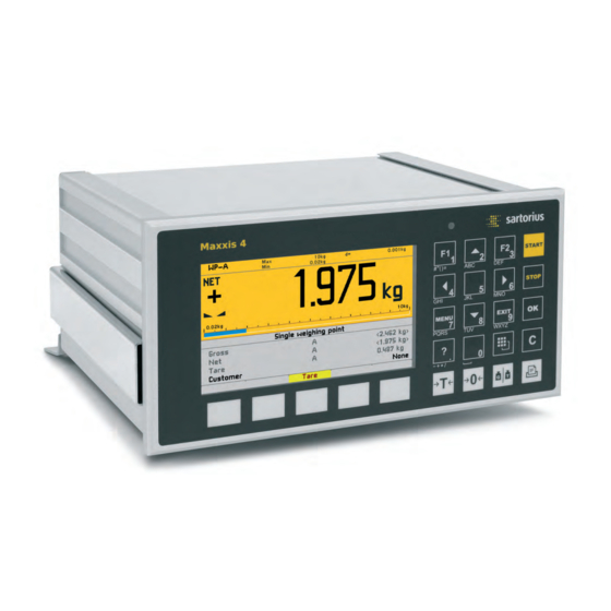
Minebea Sartorius Intec Maxxis 4 PR 5500 Instrument Manual (407 pages)
Brand:
Minebea
| Category:
Controller
| Size: 10 MB
Table of Contents
Table of Contents
3
1 Introduction
11
2 Safety Information
12
Electrical Protective Class
12
Intended Use
12
Initial Inspection
12
Before Commissioning
13
Installation
13
Opening the Instrument
14
Mains Connection and Protective Grounding Conductor for PR 5500
14
RF Interference Suppression
16
Failure and Excessive Stress
16
Important Note
16
Repairs and Maintenance
16
Static Sensitive Components
16
Replacing Fuses
16
3 Process Controller
17
General Information
17
Overview of the Instrument
17
Housing
19
Housing Dimensions
19
Housing Dimensions with Strain Relief and Reinforcing Frame
20
Control Panel Cut-Out
21
Display and Control Panel
22
Overview
22
Display
23
Operating Elements
25
Operation Using the VNC Program
29
Overview of Connections
30
Plug-In Cards
31
Application Licenses
33
Instrument Versions
34
Combinatorics for the Options
34
4 Device Installation
37
General Information
37
Mechanical Preparation
38
Hardware Construction
40
Main Board
40
Network Port
41
USB Connection
42
SD Card Slot
46
Interface (Built-In)
47
Accessories
52
PR 5500/04 2X RS-485 Interface
52
PR 5500/32 2X RS-232 Interface
62
PR 5500/07 Analog Inputs and Outputs
67
PR 5500/10 Weighing Electronics Board
69
PR 5500/12 Digital Inputs and Outputs
79
PR 5500/13 Digital Inputs and Outputs
86
PR 5500/17 Digital Inputs and Outputs
93
PR 1721/61 Profibus-DP
101
PR 1721/64 Devicenet
104
PR 1721/65 CC-Link
108
PR 1721/66 Profinet I/O
111
PR 1721/57 Ethernet-IP
114
5 Commissioning
117
Power Failure/Data Protection/Warm Start/Cold Start
117
General Information
117
Power Failure
117
Warm Start
117
Cold Start
118
Overwrite Protection
119
Switching on the Device
121
Switching off the Device
123
Warm-Up Time
123
Configuring and Calibrating Via the Front Keys/Pc Keyboard
123
Configuring and Calibrating Via a Notebook/Pc
124
Connecting the Device to the Network and Determining the IP Address
124
Activating the 'DHCP' Network
126
Searching for Devices in the Network Using 'Indicatorbrowser
128
Operation Using the VNC Client Program
129
Operation Via a Web Browser
130
Resetting Network
133
Help Function
134
Selecting the Operating Language
134
User Management
135
General Information
135
Activating User Management
135
Deactivating User Management
143
User Login/Logout
144
System Menu
145
System Setup: Connected Devices
145
System Setup: Date & Time
146
System Setup: Operating Parameters
147
System Setup: Network Parameters
148
System Setup: Network Share Connections
149
System Setup: Fieldbus Parameters
150
System Setup: Weighing Point - Weighing Point a
150
System Setup: Weighing Point: Weighing Point A: Internal Weighing Point
151
System Setup: Weighing Point: Weighing Point A: Xbpi Scale
153
System Setup: Weighing Point: Weighing Point A: SBI Scale
154
System Setup: Weighing Point: Weighing Point A: Pendeo Truck
155
System Setup: Weighing Point: Weighing Point A: Pendeo Process
158
System Setup: Weighing Point: Weighing Point A: PR-Net Weighing Point
161
System Setup: Weighing Point: Weighing Point A: Mettler-Scale
161
System Setup: Weighing Point: Weighing Point A: SMA Scale
162
System Setup: Display Settings
162
System Setup: License Settings
162
System Setup: User Management
163
Calibrating the Internal Weighing Point
164
General Information
164
Showing the Calibration Data
165
Increased Resolution (10-Fold)
166
Selecting the Calibration Mode
167
Determining the Maximum Capacity [Max]
169
Determining the Scale Interval [Scale Interval]
172
Determining the Dead Load [Dead Load At]
173
Calibrating with Weight [Max At]
175
Calibrating with MV/V [Max At]
177
Calibrating the Scale with Load Cell Data (Smart Calibration) [By Data]
178
Subsequent Dead Load Correction
179
Linearity
180
Saving the Calibration
182
Canceling Calibration
182
Display Units
183
Parameter Input
185
Configuring a Xbpi Scale
192
General Information
192
Xbpi Parameter Input for Serial Interface
192
Xbpi Parameter Input for Scale Function
193
Setting up an Xbpi Platform
195
Setting the Xbpi Dead Load
199
Xbpi Calibration with the User Weight
200
Xbpi Calibration with Automatic Weight Detection
202
Xbpi Calibration with Default Weight
203
Xbpi Calibration with Internal Weight
204
Xbpi Linearization
206
Xbpi Display Units
208
Setting the SBI Scale
209
General Information
209
Parameter for Serial Interface
209
Parametereingabe
210
Calibrating Digital Weighbridge Load Cell 'Pendeo® Truck
211
General Information
211
Parameter Input for Serial Interface
211
Calibration Sequence
212
Search for Load Cells and Set Dead Load
212
Search for Load Cells
213
View and Assign Load Cells
214
Calibrating Load Cells
217
Assign Load Cell Name
220
Service Function
220
Corner Correction
222
Parameter Input
224
Subsequent Dead Load Correction
227
Calibrating Digital Precision Compression Load Cell 'Pendeo® Process
228
General Information
228
Parameter Input for Serial Interface
228
Calibration Sequence
229
Search for Load Cells and Set Dead Load
229
Search for Load Cells
230
View and Assign Load Cells
231
Calibrating Load Cells
234
Assign Load Cell Name
237
Service Function
237
Corner Correction
239
Parameter Input
240
Subsequent Dead Load Correction
243
PR-Net Weiging Point
244
General Information
244
Parameter Input
244
Mettler-Scale
246
General Information
246
Parameter Input in Mettler-Scale Menu
246
Parameter Input for Serial Interface
246
Parameters Input for Scale Function
248
Setting the SMA Scale
250
General Information
250
Parameter for Serial Interface
250
Parametereingabe
251
General Parameter Settings
252
Equipment Settings
252
Setting the Date and Time
263
Setting the Operating Parameters
265
Network Parameters
270
Network Share Connections
272
Fieldbus Parameters
276
Display Settings
281
License Settings
282
System Information
284
Showing the Version
284
Showing the Status
285
Showing Alarm Information
286
Showing Hardware Options
287
Modbus-TCP IO Modules
288
Browsing the Alibi Memory
289
Showing Calibration Check Numbers
289
Showing Pendeo Data
289
Displaying Event Log
292
Printing out Configuration Settings
293
6 Extended Functions
294
System Maintenance
294
General Information
294
Saving to Selected Media (Backup)
294
Restoring Backup Data from External Media
299
Exporting to Selected Media
305
Importing Data from External Media
308
Alibi Memory Maintenance
313
SD Card Maintenance
324
Creating a Service Report
326
Switching off the Device
327
Updating the Software
328
Resetting the Device to the Factory Settings
339
Hardware Test
340
Functions Via the WEB Site
348
Alibi Memory
356
General Information
356
Erasing the Alibi Memory
356
Browsing the Alibi Memory
358
Exporting and Printing Alibi Data Records
361
BIOS Menu
362
General Information
362
Accessing the BIOS Menu
362
Troubleshooting Menu
364
7 Modbus Protocol
366
General Description
366
Modbus-RTU
367
Modbus-TCP/UDP
368
Functions
369
Error Messages
374
Word Addresses
375
8 EW Com Protocol
376
Weight Function Commands
376
Other Commands
377
SPM Commands
378
Error Messages for EW Com Commands
379
9 Repairs and Maintenance
380
Battery for Date/Time
380
Rechargeable Battery for Voltage Supply
380
Solder Work
380
Cleaning
381
10 Disposal
382
11 Error Messages
383
Error Messages in Measuring Circuit
383
Error Messages with Xbpi Scales
385
Error Messages
385
Error During "Set Zero" and "Set Tare
386
Error Messages with Pendeo® Load Cells
387
Error Messages with PR-Net Weighing Point
388
Error Messages with Type 'Mettler-Scale' Weighing Point
388
Error Messages During Calibration
389
Determining the Maximum Capacity (MAX)
389
Determining the Scale Interval
390
Determining the Dead Load
391
Calibrating with Weight
392
12 Specifications
393
Note on Using 'Free Software
393
Decoding the Serial Number
393
General Data
393
Battery for Date/Time
393
Rechargeable Battery for Voltage Supply
393
Display
393
Power Connection 230 V AC
393
Power Connection 24 V DC
394
Effect of Ambient Conditions
394
Ambient Conditions
394
Electromagnetic Compatibility (EMC)
394
RF Interference Suppression
395
Mechanics
395
Design
395
Dimensions
395
Weights
395
Documentation on the Enclosed CD
395
13 Appendix
396
Configuration Printout
396
Test Printout
398
Alibi Printout
399
Leds
400
Terminal Coding
401
Exchanging the Plug-In Cards
402
Safety Information
402
Optional and Fieldbus Cards
402
Replacing the Device
403
Replacing the SD Card
405
Advertisement
Advertisement
Related Products
Minebea PR 5220 Series
Minebea PR 5220/00
Minebea PR 5220/01
Minebea PR 5220/06
Minebea PR 5220/07
Minebea Categories
Measuring Instruments
Transmitter
Touch Panel
Transducer
Control Unit
More Minebea Manuals
Login
Sign In
OR
Sign in with Facebook
Sign in with Google
Upload manual
Upload from disk
Upload from URL