Table of Contents
Advertisement
Advertisement
Table of Contents

Summary of Contents for Minebea Sartorius Intec Maxxis 4 PR 5500
- Page 1 Instrument Manual Process Controller Maxxis 4 PR 5500 Instrument Manual 9499 050 55000 Edition 2 24.07.2015 for PR 5500 Release 2.20 Sartorius Mechatronics T&H GmbH, Meiendorfer Str. 205, 22145 Hamburg, Germany Tel: +49.40.67960.303 Fax: +49.40.67960.383...
- Page 2 Please note Any information in this document is subject to change without notice and does not represent a commitment on the part of SARTORIUS INTEC unless legally prescribed. This product should be operated only by trained and qualified personnel. In correspondence concerning this product the type, name and release number as well as all license numbers in relation to the product have to be quoted.
-
Page 3: Table Of Contents
PR 5500 Instrument Manual Table of Contents Table of Contents Introduction..................................1 Safety Information ................................2 Electrical Protective Class....................................2 Intended Use ........................................2 Initial Inspection ......................................2 Before Commissioning ....................................3 2.4.1 Installation ......................................3 2.4.2 Opening the Instrument ...................................4 2.4.3 Mains Connection and Protective Grounding Conductor for PR 5500 ................4 RF Interference Suppression ..................................6 Failure and Excessive Stress ..................................6 Important Note .......................................6... - Page 4 Table of Contents PR 5500 Instrument Manual Device Installation ................................27 General Information ....................................27 Mechanical Preparation .................................... 28 Hardware Construction ..................................... 30 4.3.1 Main Board ......................................30 4.3.2 Network Port ..................................... 31 4.3.3 USB Connection ....................................32 4.3.4 SD Card Slot ....................................... 36 4.3.5 RS-232 Interface (built-in) ................................
- Page 5 PR 5500 Instrument Manual Table of Contents User Management.....................................125 5.9.1 General Information ..................................125 5.9.2 Activating User Management ..............................125 5.9.3 Deactivating User Management..............................133 5.9.4 User Login/Logout..................................134 5.10 System Menu ......................................135 5.10.1 System Setup: Connected Devices ............................135 5.10.2 System setup: Date & Time .................................136 5.10.3 System setup: Operating parameters ............................137 5.10.4 System setup: Network parameters ............................138 5.10.5 System setup: Network share connections ..........................139...
- Page 6 Table of Contents PR 5500 Instrument Manual 5.12 Configuring a xBPI Scale ..................................182 5.12.1 General Information ..................................182 5.12.2 xBPI Parameter Input for Serial Interface ..........................182 5.12.3 xBPI Parameter Input for Scale Function..........................183 5.12.4 Setting up an xBPI Platform ..............................185 5.12.5 Setting the xBPI Dead Load ................................189 5.12.6 xBPI Calibration with the User Weight ...........................190 5.12.7 xBPI Calibration with Automatic Weight Detection ......................192 5.12.8 xBPI Calibration with Default Weight .............................193...
- Page 7 PR 5500 Instrument Manual Table of Contents 5.16 PR-Net Weiging Point .....................................234 5.16.1 General Information ..................................234 5.16.2 Parameter Input .....................................234 5.17 Mettler-Scale ......................................236 5.17.1 General Information ..................................236 5.17.2 Parameter Input in Mettler-Scale Menu ..........................236 5.17.3 Parameter Input for Serial Interface ............................236 5.17.4 Parameters Input for Scale Function ............................238 5.18 Setting the SMA Scale .....................................240 5.18.1 General Information ..................................240...
- Page 8 Table of Contents PR 5500 Instrument Manual Extended Functions ............................... 284 System Maintenance ....................................284 6.1.1 General Information ..................................284 6.1.2 Saving to selected Media (Backup) ............................284 6.1.3 Restoring Backup Data from External Media ........................289 6.1.4 Exporting to selected Media ..............................295 6.1.5 Importing Data from External Media ............................298 6.1.6 Alibi Memory Maintenance ................................303...
- Page 9 PR 5500 Instrument Manual Table of Contents ModBus Protocol ................................356 General Description ....................................356 ModBus-RTU .......................................357 ModBus-TCP/UDP......................................358 Functions ........................................359 Error Messages ......................................364 Word Addresses ......................................365 EW Com Protocol ................................366 Weight Function Commands .................................366 Other Commands ......................................367 SPM Commands ......................................368 Error Messages for EW Com Commands............................369 Repairs and Maintenance .............................
- Page 10 Table of Contents PR 5500 Instrument Manual Specifications ................................. 383 12.1 Note on Using ‘Free Software’ ................................383 12.2 Decoding the Serial Number .................................383 12.3 General Data .......................................383 12.3.1 Battery for Date/Time ...................................383 12.3.2 Rechargeable Battery for Voltage Supply ..........................383 12.3.3 Display .......................................383 12.3.4 Power Connection 230 V AC ..............................383 12.3.5 Power Connection 24 V DC.................................384 12.4 Effect of Ambient Conditions ................................384...
-
Page 11: Introduction
PR 5500 Instrument Manual Introduction Introduction Please read all the instructions carefully and completely before using the instrument. Read the safety precautions carefully. These instructions are part of the product. Keep them in a safe and easily accessible location. Symbols and Signs The following symbols are used in this manual: Warning of dangerous electrical voltage. -
Page 12: Safety Information
Safety Information PR 5500 Instrument Manual Safety Information 2.1 Electrical Protective Class Warning! This instrument has been built and tested in compliance with the safety regulations for measuring and control instrumentation for protective class I (protective grounding conductor) according to IEC 1010/EN 61010 or VDE 0411. The instrument was in ! Warnung perfect condition with regard to safety features when it left the factory. -
Page 13: Before Commissioning
PR 5500 Instrument Manual Safety Information 2.4 Before Commissioning Visual inspection! Before commissioning as well as after storage or transport, inspect the device visually for signs of mechanical damage. 2.4.1 Installation Design Protection class Installation Control cabinet housing IP 65, back IP 20 Control Panel Cut-Out To ensure proper cooling of the instrument, make sure air circulation around the instrument is not blocked. -
Page 14: Opening The Instrument
Safety Information PR 5500 Instrument Manual 2.4.2 Opening the Instrument High Voltage! Working on the instrument while it is switched on may have life-threatening consequences. Disconnect the instrument from the supply voltage. ! Danger When removing covers or parts using tools, live parts or terminals may be exposed. Please note that capacitors in the instrument may still be charged even after disconnecting the device from all voltage sources. - Page 15 PR 5500 Instrument Manual Safety Information 2.4.3.2 Version 24 V DC Mains connection This version is designed for 24 V direct current. The supply is established via three spring clamp terminals (+ PE -). The instrument is protected against incorrect polarity. Protective grounding conductor The protective grounding must be connected to the central terminal (PE).
-
Page 16: Rf Interference Suppression
PR 5500 Instrument Manual Safety Information 2.5 RF Interference Suppression The device is intended for use in the industrial sector and can cause RF interference if used in residential areas (see Chapter 12.4.3). In this case, the operator may be required to put suitable countermeasures in place. 2.6 Failure and Excessive Stress If there is any reason to assume that safe operation of the instrument is no longer ensured, shut it down and make sure it cannot be used. -
Page 17: Process Controller
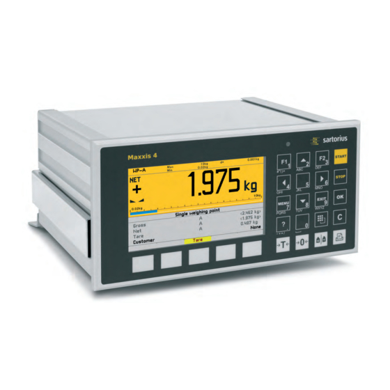
PR 5500 Instrument Manual Process Controller Process Controller 3.1 General Information This instrument is equipped with a TFT color display, and a function/alphanumeric keypad. With the corresponding application, this device is a powerful system for managing/documenting weighing and dosing processes. It combines the functions of a user-friendly interface as well as a weighing and dosing instrument, PLC and interfaces. - Page 18 Process Controller PR 5500 Instrument Manual Communication Protocols For the internal RS-232: Fieldbus slave (accessories): Remote display protocol PR 1721/61 ProfiBus DP Printer PR 1721/64 DeviceNet ModBus protocol PR 1721/65 CC Link xBPI protocol PR 1721/66 ProfiNet I/O SBI protocol PR 1721/67 EtherNet IP EW-Com protocol For the internal LAN interface:...
-
Page 19: Housing
PR 5500 Instrument Manual Process Controller 3.3 Housing 3.3.1 Housing dimensions The keypad and the display form one unit with the front. A rectangular cut-out is required for the installation. Cable connections are made at the back of the housing. Front view Side view Reset key... -
Page 20: Housing Dimensions With Strain Relief And Reinforcing Frame
Process Controller PR 5500 Instrument Manual 3.3.2 Housing Dimensions with Strain Relief and Reinforcing frame The dimensions with the following options must be observed for installation: Pos. Designation Reinforcing frame Screen clamping rail Cable clamps Side view Front view Back view Note All dimensions in mm. -
Page 21: Control Panel Cut-Out
PR 5500 Instrument Manual Process Controller 3.3.3 Control Panel Cut-Out The control panel cut-out must be made before installing the unit. +0.5 Note All dimensions in mm. Sartorius EN-11... -
Page 22: Display And Control Panel
Process Controller PR 5500 Instrument Manual 3.4 Display and Control Panel 3.4.1 Overview 4.3” color display Alphanumeric/function keys Softkeys Navigation/Menu keys Indicator keys EN-12 Sartorius... -
Page 23: Display
PR 5500 Instrument Manual Process Controller 3.4.2 Display The TFT display shows weight values of up to 7 digits with a decimal point and a plus or minus sign. Available weight units are t, kg, g, mg, lb and oz. The current weight value is displayed under the weight display as a bar graph in relation to the maximum capacity. - Page 24 Process Controller PR 5500 Instrument Manual Value type/Polarity sign Zero/Standstill/Dosing/Monitor. Symbols Mass unit Gross weight Weight value standstill Gross weight in NTEP or The gross weight NSC mode value is within ±¼ d of zero Net weight Filling mode: flashes when filling is (Net = gross - tare) “held”;...
-
Page 25: Operating Elements
PR 5500 Instrument Manual Process Controller 3.4.3 Operating Elements 3.4.3.1 Front keys The following table shows the basic meanings of symbols for the front keys. The keys could have additional meanings depending on the applications used. Indicator keys Tare Display gross/tare weight The current gross weight is stored in You switch to the next weight by the tare memory if... - Page 26 Process Controller PR 5500 Instrument Manual Navigation/menu keys Scroll up in the menu Confirm entry/selection Scroll down in the menu Cancel entry/selection (after a EXIT security prompt), without saving the change. Exit the parameter/menu window Cursor moves to the left Pressing the Delete key deletes ...
- Page 27 PR 5500 Instrument Manual Process Controller Alphanumeric keypad Toggle key Pressing this will toggle between the following input modes: Cursor Uppercase letters Lowercase letters Pinyin When Chinese was selected or set under [Operating parameters] - [Input method]. Hepburn When Japanese was selected or set under [Operating parameters] - [Input method].
- Page 28 Process Controller PR 5500 Instrument Manual Input with character table Double-clicking the key displays the character table. Note The toggle function is turned off. Procedure Select the desired character with the cursor. y The selected character is shown magnified in the field at the top right.
-
Page 29: Operation Using The Vnc Program
PR 5500 Instrument Manual Process Controller 3.4.3.2 Operation Using Soft Keys The functions of the five soft keys below the graphic display are indicated in the bottommost text line of the display. In the descriptions of operating sequences which entail the use of soft keys, the soft key function to be selected is shown in square brackets;... -
Page 30: Overview Of Connections
Process Controller PR 5500 Instrument Manual 3.5 Overview of Connections EN-20 Sartorius... -
Page 31: Plug-In Cards
PR 5500 Instrument Manual Process Controller 3.5.1 Plug-in Cards Product ID Description Position PR 5500/04 The interface can be configured via Option-1/FB and/or Option-2 the software. 2 serial RS-485 interfaces For more information, see Chapter 4.4.1. PR 5500/07 Analog input: Option-1/FB and/or Option-2 internal 14 bits binary = 20,000 1 analog input... - Page 32 Process Controller PR 5500 Instrument Manual Product ID Description Position PR 1721/61 ProfiBus-DP-V0 Slave with Option-1/FB 9.6 kbit/s to 12 Mbps, Auto (Carrier card installed in reversed ProfiBus-DP baud rate detection; For more position) information, see Chapter 4.4.8. PR 1721/64 DeviceNet Master-Slave with 125, Option-1/FB 250 and 500 kbps...
-
Page 33: Application Licenses
PR 5500 Instrument Manual Process Controller 3.5.2 Application Licenses Examples of application licenses: Type Function PR 5500/92 PR 1792 OPC server (AccessIt 2.0 license incl.) PR 5500/83 Batching Examples of application packages: Checkweighing Automatic dosing and manual filling For product details, see corresponding data sheets/manuals. Applications purchased from Sartorius Intec may only be changed as per a source code agreement. -
Page 34: Instrument Versions
Process Controller PR 5500 Instrument Manual 3.6 Instrument Versions 3.6.1 Combinatorics for the Options Name Accessory Code no. Description Chapter Housing: Control cabinet housing Standard 3.3.1 Housing mounting parts: Strain relief for connecting cables L14 3.3.2 Reinforcing frame 3.3.2 Elektronik: Analog/digital PR5500/10 WPA: Weighing electronics board... - Page 35 PR 5500 Instrument Manual Process Controller Name Accessory Code no. Description Chapter Interface cards: Option-1/FB: 2 serial interfaces 2x RS-485 PR 5500/04 4.4.1 interface Option-2: 2 serial interfaces Option-1/FB: 1 analog input and 1 analog output (0/4 to 20 mA) Analog inputs PR 5500/07 4.4.3...
- Page 36 Process Controller PR 5500 Instrument Manual Name Accessory Code no. Description Chapter Applications/Alibi memory/OPC server: Basic Standard application Phase PR 5500/81 Application (OPC license incl.) Batching PR 5500/83 Application see corre- PR 5500/86 Application sponding manual Tilt Correction PR 5500/87 License (only ‚Basic‘...
-
Page 37: Device Installation
PR 5500 Instrument Manual Device Installation Device Installation 4.1 General Information Before starting work, please read Chapter 2 and follow all instructions. Further procedures: Check the consignment: make sure that all components are present. Safety check: inspect all components for damage. Make sure that the on-site installation is correct and complete including cables, e.g. -
Page 38: Mechanical Preparation
Device Installation PR 5500 Instrument Manual 4.2 Mechanical Preparation Have all required parts, technical documents and tools at hand for installation. Measurement cables should be kept away from power equipment. Signal cables and measurement cables should be installed separately from electric power lines. It is recommended to lay measurement cables in separate cable conduits. - Page 39 PR 5500 Instrument Manual Device Installation 4.2.1.1 Connecting the Screen to the Screen Clamping Rail The screen must be connected to the screen clamping rail using delivered screen clamps as pictured below. 4.2.1.2 Connecting the Equipotential Bonding Conductor The equipotential bonding conductor (1) must be connected as pictured below. Sartorius EN-29...
-
Page 40: Hardware Construction
Device Installation PR 5500 Instrument Manual 4.3 Hardware Construction 4.3.1 Main Board The following elements are located on the main board: Pos. Name Pos. Name Reset key Slot for fieldbus and option cards, Option-1/FB Ethernet port, internal Weighing electronics board W1 USB connection Stand-by battery (for data recovery) Slot for option cards, Option-2... -
Page 41: Network Port
PR 5500 Instrument Manual Device Installation 4.3.2 Network Port The device has an internal Ethernet port. 4.3.2.1 Ethernet Port The Ethernet port contains a powerful TCP/IP interface connection with transfer rates of 10 or 100 Mbps. Function tests can be made via the LEDs (green and yellow) in the RJ-45 socket. Transmission rate 10 Mbps (10 Base-T), 100 Mbps (100 Base-T),... -
Page 42: Usb Connection
Device Installation PR 5500 Instrument Manual 4.3.3 USB Connection The USB connection is located on the back of the device. Type USB 2.0, Type A Max. current = 200 mA Possible USB stick Connection External keyboard Devices Barcode reader Printer (non-GDI) External splitter (hub) Data integrity cannot be guaranteed in the case of a power failure when using a USB stick via a splitter (HUB). - Page 43 PR 5500 Instrument Manual Device Installation Before connecting the keyboard, make sure: Current consumption i <200 mA. An electronic current limiting prevents overloads. ! Caution 1 2 3 4 5 6 7 8 Sartorius EN-33...
- Page 44 Device Installation PR 5500 Instrument Manual 4.3.3.3 Barcode scanner A barcode scanner can be connected to the USB interface on the back of the device as an alternative to an external keyboard. Before connecting the barcode scanner, make sure: current consumption i <200 mA. An electronic current limiting prevents overloads.
- Page 45 PR 5500 Instrument Manual Device Installation 4.3.3.4 Printer The following USB printers can be used: YDP14IS-OCEUV EPSON TM-U220 und EPSON LQ-300K Line printer Printer with ESC/P2 control Printer with PCL5 control 4.3.3.5 External HUB All commercially-available HUBs can be used. All connected USB devices + HUB: current consumption i <200 mA or use a power supply for the HUB.
-
Page 46: Sd Card Slot
Device Installation PR 5500 Instrument Manual 4.3.4 SD Card Slot The internal SD card slot is located on the back of the device. It comes with an appropriate SD card. The SD card is only used for storage; it is not used for data transfers. Note Only Sartorius Intec-supplied SD cards may be used. -
Page 47: Interface (Built-In)
PR 5500 Instrument Manual Device Installation 4.3.5 RS-232 Interface (built-in) The device is equipped with an integrated RS-232 interface. This interface is configurable, and can be used, for example, for data transmission to a remote display or printer. Connection Terminal, 5-pin Number of channels Type... - Page 48 Device Installation PR 5500 Instrument Manual 4.3.5.1 Connecting a PR 5110 Remote Display via RS-232 The remote display can be connected via the built-in RS-232 interface. PR 5110 PR 5500 RS-232: D-Sub 9-contact male connector/ Builtin or/oder 9-polige D-Sub Buchse (male) PR5510/02 or/oder PR5510/04 RS-232...
- Page 49 PR 5500 Instrument Manual Device Installation 4.3.5.2 Connecting a YDP14IS Ticket Printer via RS-232 The YDP14IS-OCEUV ticket printer can be connected via the built-in RS-232 interface. delievered adapter mitgelieferter Adapter PR 5500 YDP 14IS-OCEUV RS-232 RS-232 PR 5500 Configuration Printer Configuration [System setup]-[Connected devices]-[Printer]- The printer must be set to Line Mode (the factory [Interface]-[Built-in RS-232]:...
- Page 50 Device Installation PR 5500 Instrument Manual 4.3.5.4 Connecting an IS Platform via RS-232 A platform using an xBPI or SBI protocol can be connected via the built-in RS-232 interface. PR 5500 Sartorius platform/Plattform xBPI protocol (slave)/xBPI Protokoll (slave) RS-232 12-contact male socket/ 12-polige Buchse (male) AC/DC adapter/ AC/DC Adapter...
- Page 51 PR 5500 Instrument Manual Device Installation 4.3.5.5 Connecting a Mettler-Scale via RS-232 A Mettler-Scale using MT-SICS protocol can be connected via the built-in RS-232 interface. Example: Type XS6002SDR PR 5500 Mettler-Scale/Waage type/Typ XS6002SDR MT-SICS protocol (slave)/MT-SCIS-Protokoll (slave) RS-232 Configuration PR 5500 [System setup] –...
-
Page 52: Accessories
Device Installation PR 5500 Instrument Manual 4.4 Accessories 4.4.1 PR 5500/04 2x RS-485 Interface The plug-in card contains two channels. One channel can be used for connecting an IS platform without an external power supply. Note Either the internal Weighingpoint or an IS platform without external power supply can be used. - Page 53 PR 5500 Instrument Manual Device Installation PR 5500/04 2x RS-485 Interface ↓ 1 2 3 4 5 6 7 8 1 2 3 4 5 6 7 8 ↓ 1 2 3 4 5 6 7 8 1 2 3 4 5 6 7 8 Coding of Option-1/Option-2 Terminal block: Insert the coding pin into the slot of the position marked in gray.
- Page 54 Device Installation PR 5500 Instrument Manual Block diagram 2x RS-485 PR 5500/04 +24 V B-GNDI RxD/TxD-P B-TxB RxD/TxD-N B-TxA B-RxB B-RxA +24 V A-GNDI RxD/TxD-P A-TxB RxD/TxD-N A-TxA A-RxB A-RxA EN-44 Sartorius...
- Page 55 PR 5500 Instrument Manual Device Installation Function Settings for RS-485 Rx bus termination OFF: not connected ON: (A-RxA 120 ¥ A-RxB) Tx pull-up resistor OFF: not connected ON: (A-TxB 1K6 ¥ +V) Tx pull-down resistor OFF: not connected ON: (A-TxA 1K6 ¥ -V) Tx bus termination OFF: not connected ON: (A-TxA 120 ¥...
- Page 56 Device Installation PR 5500 Instrument Manual 4.4.1.2 Connecting to a PLC or RS-485/RS-232 Converter Point-to-point connection for the ModBus protocol (2-wire) Example PR 5500 PR 5500/04 RS-485-A ModBus-RTU (master) + 24 V GNDI RxD/TxD-P A-TxB TxB/RxB RxD/TxD-N A-TxA TxA/RxA A-RxB A-RxA Switch settings S2, S3, S4...
- Page 57 PR 5500 Instrument Manual Device Installation 4.4.1.3 Connecting several PR 5500 Devices to a PC or RS-485/RS-232 Converter Connection for the EW Com protocol. Example PR 5500 PR 5500/04 RS-485-A + 24 V RS-485 Converter GNDI RxD/TxD-P A-TxB RxD/TxD-N A-TxA A-RxB A-RxA Switch settings/Schalterstellungen...
- Page 58 Device Installation PR 5500 Instrument Manual 4.4.1.4 Connecting a PR 5110 Remote Display via RS-485 Connection via the RS-485 interface, 4-wire transmission, point-to-point, full duplex (simultaneous sending and receiving possible) with the PR 5110 remote display. Example PR 5500 PR 5500/04 D-Sub 9-contact male connector/ RS-485-A 9-polige D-Sub Buchse (male)
- Page 59 PR 5500 Instrument Manual Device Installation 4.4.1.5 Connecting multiple PR 5110 Remote Displays via RS-485 Connection of several remote displays via the RS-485 interface, 4-wire, full-duplex (simultaneous sending and receiving possible). Example PR 5500 PR 5500/04 D-Sub 9-contact male connector/ RS-485-A 9-polige D-Sub Buchse (male) PR5110...
- Page 60 Device Installation PR 5500 Instrument Manual 4.4.1.6 Connecting the IS Platform via RS-485 (2-wire) A platform using an xBPI or SBI protocol can be connected via the RS-485 interface. Note Only one platform can be supplied with power from the PR 5500 and the weighing electronics board PR 5500/10 must not be connected.
- Page 61 PR 5500 Instrument Manual Device Installation 4.4.1.7 Connecting 4 Load Cells PR 6204 ‚Pendeo® Process‘/PR 6224 ‚Pendeo® Truck‘ via RS-485 Example PR 6024/64S LC 3 LC 1 – – 24 V DC 1 AT LC 4 LC 2 – – + –...
-
Page 62: Pr 5500/32 2X Rs-232 Interface
Device Installation PR 5500 Instrument Manual 4.4.2 PR 5500/32 2x RS-232 Interface The plug-in card contains two channels. One channel can be used for connecting one IS platform without an external power supply. The jumper (1) must then be plugged onto A-24 V or B-24V. When an IS platform is connected without an external power supply, no analog weighing electronics board or no load cells may be installed in the device. - Page 63 PR 5500 Instrument Manual Device Installation PR 5500/32 2x RS-232 Interface 24 V 24 V Coding of Option-1/Option-2 Terminal block: Insert the coding pin into the slot of the position marked in gray. Terminal: Remove (pinch off) the corresponding coding ridge. Note The terminal coding is described in Chapter 13.5.
- Page 64 Device Installation PR 5500 Instrument Manual Block diagram 2x RS-232 PR 5500/32 +24 V B- +24 V B-RTS B-TxD B-RxD B-CTS +24 V A- +24 V A-RTS A-TxD A-RxD A-CTS EN-54 Sartorius...
- Page 65 PR 5500 Instrument Manual Device Installation 4.4.2.1 Connecting peripheral devices via RS-232 Connecting the PR 5110 Remote Display via RS-232 (see built-in RS-232, Chapter 4.3.5.1) Connecting a YDP14IS Ticket Printer via RS-232 (see built-in RS-232, Chapter 4.3.5.2) Connecting a Mettler-Scale via RS-232 (see built-in RS-232, Chapter 4.3.5.5) Sartorius EN-55...
- Page 66 Device Installation PR 5500 Instrument Manual 4.4.2.2 Connecting the IS Platform via RS-232 Using these option cards, you can connect an IS platform using the xBPI or SBI protocol. Note Only one platform can be supplied with power from the PR 5500 and no load cells may be connected to the weighing electronics board PR 5500/10.
-
Page 67: Pr 5500/07 Analog Inputs And Outputs
PR 5500 Instrument Manual Device Installation 4.4.3 PR 5500/07 Analog Inputs and Outputs The plug-in card for the available analog channels has 1 analog output (active) and 1 analog input. The card is inserted in the Option 1/FB and/or Option 2 slot. A max. - Page 68 Device Installation PR 5500 Instrument Manual Coding of Option-1/Option-2 Terminal block: Insert the coding pin into the slot of the position marked in gray. Terminal: Remove (pinch off) the corresponding coding ridge. Note The terminal coding is described in Chapter 13.5. EN-58 Sartorius...
-
Page 69: Pr 5500/10 Weighing Electronics Board
PR 5500 Instrument Manual Device Installation 4.4.4 PR 5500/10 Weighing Electronics Board 4.4.4.1 Specifications The weighing electronics board is inserted in the WP A slot. The CAL switch A (1) are located on the board. Adjustment data and parameters are saved to the EAROM (non-volatile memory) of the weighing electronics board. - Page 70 Device Installation PR 5500 Instrument Manual 4.4.4.2 General Information There is one connection on the back of the housing for analog load cells or analog platforms (e.g. CAPP series) depending on the model. The supply voltage is protected against short circuit and overload. Do not shorten the load cell cable.
- Page 71 PR 5500 Instrument Manual Device Installation 4.4.4.3 Connecting a Load Cell with a 4-Wire Cable The cable colors shown here are valid for Sartorius Intec load cells. Color code: Black ! Caution Blue White Green Yellow Gray M+ M V+ S –...
- Page 72 Device Installation PR 5500 Instrument Manual 4.4.4.4 Connecting a Load Cell with a 6-Wire Cable The cable colors shown here are valid for Sartorius Intec load cells. Color code: Black ! Caution Blue White Green Yellow Gray M+ M V+ S –...
- Page 73 PR 5500 Instrument Manual Device Installation 4.4.4.5 Connecting up to 8 Load Cells (650 ¥) using a 6-Wire Connecting Cable Connections are made via junction box PR 6130/.. using connecting cable PR 6135. The cable colors shown above are valid for Sartorius Intec load cells and connecting cable PR 6135.
- Page 74 Device Installation PR 5500 Instrument Manual screen/ Schirm M+ M– V+ S+ S– V– EN-64 Sartorius...
- Page 75 PR 5500 Instrument Manual Device Installation 4.4.4.6 Testing the Measuring Circuit You can perform a simple test on connected load cells using a multimeter (The internal load cell power supply does not apply to load cells supplied externally.): Measuring voltage: 0 - 12 mV = @ LC with 1.0 mV/V 0 - 24 mV = @ LC with 2.0 mV/V 0 V ±0.5 V...
- Page 76 Device Installation PR 5500 Instrument Manual 4.4.4.7 Connecting Load Cells to an External Supply When the total resistance of the load cells is <75 ¥ (e.g. more than 4 load cells with 350 ¥), an external load cell supply is required. In this case, the internal supply is replaced by a potential-free external supply. The center of the external supply voltage (0 ext.
- Page 77 PR 5500 Instrument Manual Device Installation 4.4.4.8 Connecting Weighing Platforms (CAP) Up to 2 Combics analog platforms (CAP series) can be connected to the internal weighing electronics connections depending on the model. The cable colors shown above are valid for a CAPP4 500 x 400 and a CAPP1 320 x 420, for example.
- Page 78 Device Installation PR 5500 Instrument Manual The following example shows a platform with a 4-wire connection: M+ M V+ S – – – or screen clamping rail/ oder Schirmklemmschiene Cable screens should be connected to the device earthing terminals or screen clamping rail. The following links should be set directly on the terminal block for platforms with a 4-wire connection: ...
-
Page 79: Pr 5500/12 Digital Inputs And Outputs
PR 5500 Instrument Manual Device Installation 4.4.5 PR 5500/12 Digital Inputs and Outputs The plug-in card has 4 passive opto-decoupled inputs for process control. The plug-in card also has 4 digital outputs with potential-free two-way contacts for process control. The card is inserted in the Option 1/FB and/or Option 2 slot. A max. - Page 80 Device Installation PR 5500 Instrument Manual 4.4.5.1 Digital Inputs (PR 5500/12) Illustration: terminal coding and internal circuit CH 4 CH 3 − + − + CH 2 CH 1 − + − + Coding of Option-1 Terminal block: Insert the coding pin into the slot of the position marked in gray. Terminal: Remove (pinch off) the corresponding coding ridge.
- Page 81 PR 5500 Instrument Manual Device Installation Illustration: terminal coding and internal circuit CH 4 CH 3 − + − + CH 2 CH 1 − + − + Coding of Option-2 Terminal block: Insert the coding pin into the slot of the position marked in gray. Terminal: Remove (pinch off) the corresponding coding ridge.
- Page 82 Device Installation PR 5500 Instrument Manual Connection example for PR 5500/12: Digital Inputs PR 1624 24 V DC 0.5 A − grounding terminal or screen clamping rail/ Erdungsklemme oder Schirmklemmschiene CH 3 CH 4 − + − + CH 2 CH 1 −...
- Page 83 PR 5500 Instrument Manual Device Installation 4.4.5.2 Digital Outputs (PR 5500/12) Illustration: terminal coding and internal circuit CH4C CH4B CH3O CH4O CH3C CH3B CH2C CH2B CH1O CH2O CH1C CH1B Coding of Option-1 Terminal block: Insert the coding pin into the slot of the position marked in gray. Terminal: Remove (pinch off) the corresponding coding ridge.
- Page 84 Device Installation PR 5500 Instrument Manual Illustration: terminal coding and internal circuit CH4C CH4B CH3O CH4O CH3C CH3B CH2C CH2B CH1O CH2O CH1C CH1B Coding of Option-2 Terminal block: Insert the coding pin into the slot of the position marked in gray. Terminal: Remove (pinch off) the corresponding coding ridge.
- Page 85 PR 5500 Instrument Manual Device Installation Connection example for PR 5500/12: Connection example for PR 5500/12: Relay control (current output) Voltage output grounding terminal or grounding terminal or screen clamping rail/ screen clamping rail/ Erdungsklemme oder Erdungsklemme oder Schirmklemmschiene Schirmklemmschiene CH4C CH4B CH4C...
-
Page 86: Pr 5500/13 Digital Inputs And Outputs
Device Installation PR 5500 Instrument Manual 4.4.6 PR 5500/13 Digital Inputs and Outputs The plug-in card has 4 active opto-decoupled inputs for process control. The plug-in card also has 4 digital outputs with potential-free two-way contacts for process control. The card is inserted in the Option 1/FB and/or Option 2 slot. A max. - Page 87 PR 5500 Instrument Manual Device Installation 4.4.6.1 Digital Inputs (PR 5500/13) Illustration: terminal coding and internal circuit CH 4 CH 3 − + − + CH 2 CH 1 − + − + Coding of Option-1 Terminal block: Insert the coding pin into the slot of the position marked in gray. Terminal: Remove (pinch off) the corresponding coding ridge.
- Page 88 Device Installation PR 5500 Instrument Manual Illustration: terminal coding and internal circuit CH 4 CH 3 − + − + CH 2 CH 1 − + − + Coding of Option-2 Terminal block: Insert the coding pin into the slot of the position marked in gray. Terminal: Remove (pinch off) the corresponding coding ridge.
- Page 89 PR 5500 Instrument Manual Device Installation Connection example for PR 5500/13: Digital Inputs − grounding terminal or screen clamping rail/ Erdungsklemme oder Schirmklemmschiene CH 3 CH 4 − + − + CH 2 CH 1 − + − + Sartorius EN-79...
- Page 90 Device Installation PR 5500 Instrument Manual 4.4.6.2 Digital Outputs (PR 5500/13) Illustration: terminal coding and internal circuit CH4C CH4B CH3O CH4O CH3C CH3B CH2C CH2B CH1O CH2O CH1C CH1B Coding of Option-1 Terminal block: Insert the coding pin into the slot of the position marked in gray. Terminal: Remove (pinch off) the corresponding coding ridge.
- Page 91 PR 5500 Instrument Manual Device Installation Illustration: terminal coding and internal circuit CH4C CH4B CH3O CH4O CH3C CH3B CH2C CH2B CH1O CH2O CH1C CH1B Coding of Option-2 Terminal block: Insert the coding pin into the slot of the position marked in gray. Terminal: Remove (pinch off) the corresponding coding ridge.
- Page 92 Device Installation PR 5500 Instrument Manual Connection example for PR 5500/13: Connection example for PR 5500/13: Relay control (current output) Voltage output grounding terminal or grounding terminal or screen clamping rail/ screen clamping rail/ Erdungsklemme oder Erdungsklemme oder Schirmklemmschiene Schirmklemmschiene CH4C CH4B CH4C...
-
Page 93: Pr 5500/17 Digital Inputs And Outputs
PR 5500 Instrument Manual Device Installation 4.4.7 PR 5500/17 Digital Inputs and Outputs The plug-in card has 6 passive opto-decoupled inputs and 8 digital outputs for process control. GND (-) for all inputs and outputs together. The card is inserted in the Option 1/FB and/or Option 2 slot. A max. - Page 94 Device Installation PR 5500 Instrument Manual 4.4.7.1 Digital Inputs (PR 5500/17) Illustration: terminal coding and internal circuit CH 6 CH 5 CH 4 CH 3 CH 2 CH 1 Coding of Option-1 Terminal block: Insert the coding pin into the slot of the position marked in gray. Terminal: Remove (pinch off) the corresponding coding ridge.
- Page 95 PR 5500 Instrument Manual Device Installation Illustration: terminal coding and internal circuit CH 6 CH 5 CH 4 CH 3 CH 2 CH 1 Coding of Option-2 Terminal block: Insert the coding pin into the slot of the position marked in gray. Terminal: Remove (pinch off) the corresponding coding ridge.
- Page 96 Device Installation PR 5500 Instrument Manual Connection example for PR 5500/17: Digital Inputs PR 1624 24 V DC 0.5 A − grounding terminal or screen clamping rail/ Erdungsklemme oder Schirmklemmschiene CH 6 CH 5 CH 4 CH 3 CH 2 CH 1 EN-86 Sartorius...
- Page 97 PR 5500 Instrument Manual Device Installation Connection example for PR 5500/17: Digital inputs without potential isolation PR 5500/17 ..24 V: 2.2 K…10 K 5 V: 1.0 K supply unit Connection example for PR 5500/17: Digital inputs with potential isolation PR 5500/17 supply unit Sartorius...
- Page 98 Device Installation PR 5500 Instrument Manual 4.4.7.2 Digital Outputs (PR 5500/17) Illustration: terminal coding and internal circuit Coding of Option-1 Terminal block: Insert the coding pin into the slot of the position marked in gray. Terminal: Remove (pinch off) the corresponding coding ridge. Note The terminal coding is described in Chapter 13.5.
- Page 99 PR 5500 Instrument Manual Device Installation Illustration: terminal coding and internal circuit Coding of Option-2 Terminal block: Insert the coding pin into the slot of the position marked in gray. Terminal: Remove (pinch off) the corresponding coding ridge. Note The terminal coding is described in Chapter 13.5. Sartorius EN-89...
- Page 100 Device Installation PR 5500 Instrument Manual Connection example for PR 5500/17: Relay control (current output) grounding terminal or screen clamping rail/ Erdungsklemme oder Schirmklemmschiene The relay switches when the output is active (true). To protect the output circuit, relays must be equipped with free-wheel diodes.
-
Page 101: Pr 1721/61 Profibus-Dp
PR 5500 Instrument Manual Device Installation 4.4.8 PR 1721/61 ProfiBus-DP 4.4.8.1 Specifications Communication protocols and the syntax comply with the ProfiBus-DP standard according to IEC 61158/ EN 50170, with transfer rates up to 12 Mbps. The card is inserted in the Option 1/FB slot, see Chapter 13.6. Internal connection Pin strip, 50-pin External connection... - Page 102 Device Installation PR 5500 Instrument Manual 4.4.8.2 LEDs Identification Description Operating mode LED Status LED PROFIBUS DP Operating mode (OP) LED status Description Comments Module is offline No power Constant green Module is online Data exchange is possible Flashing 1 Hz green Module is online Module is ready for data exchange Flashing 1 Hz red...
- Page 103 PR 5500 Instrument Manual Device Installation 4.4.8.3 Assignment of the 9-pin D-sub socket (female) E. g.: SIMATIC NET PROFIBUS FAST CONNECT 390 O Ω OΩ OΩ OFF ON D (P) D (N) Connection assignment Signal Color Description EN 50170 Housing ---------------- Screen n.c.
-
Page 104: Pr 1721/64 Devicenet
Device Installation PR 5500 Instrument Manual 4.4.9 PR 1721/64 DeviceNet 4.4.9.1 Specifications The fieldbus card contains all functionalities to make a complete DeviceNet slave with a CAN controller and transmission speeds up to 500 kbps. The card is inserted in the Option-1/FB slot, see Chapter 13.6. Internal connection Pin strip, 50-pin External connection... - Page 105 PR 5500 Instrument Manual Device Installation 4.4.9.2 LEDs Identification Description Network status LED Module status LED DeviceNet Network status (NS) LED status Description Comments Module is offline No power Constant green Module is online There are one or more connections Flashing 1 Hz green Module is online No connections...
- Page 106 Device Installation PR 5500 Instrument Manual 4.4.9.3 5-Pole Terminal Block Allocation Signal Color Description Cable sheath Special DeviceNet cable (certified) 1 --------------------------- V – Black Negative power supply 2 --------------------------- CAN_L Blue CAN_L bus signal 3 ------------ Cable screen 4 --------------------------- CAN_H White CAN_H bus signal...
- Page 107 PR 5500 Instrument Manual Device Installation 4.4.9.4 Connection Diagram for a Master with three Slaves PR 1721/64 PR 5500 last Slave CAN_H CAN_L PR 5500 PR 1721/64 Slave CAN_H CAN_L PR 5500 PR 1721/64 Slave CAN_H CAN_L DeviceNet Master CAN_H CAN_L PR 5500/..
-
Page 108: Pr 1721/65 Cc-Link
Device Installation PR 5500 Instrument Manual 4.4.10 PR 1721/65 CC-Link 4.4.10.1 Specifications The fieldbus card contains all functions to provide a complete CC link slave with transfer rates up to 10 Mbps. The card is inserted in the Option-1/FB slot, see Chapter 13.6. Internal connection Pin strip, 50-pin External connection... - Page 109 PR 5500 Instrument Manual Device Installation 4.4.10.2 LEDs Pos. Description Process LED Error LED CC-Link Operation (1) LED status Description Comments Module is offline No network connection No power Constant green Module is online There is a network connection Normal operation Constant red Exception error Module is in the EXCEPTION...
- Page 110 Device Installation PR 5500 Instrument Manual 4.4.10.3 5-Pole Terminal Block Allocation Signal Description 1 --------------------------- Communication RS-485 RxD/TxD (+) 2 --------------------------- Communication RS-485 RxD/TxD (–) 3 --------------------------- Digital ground 4 ------------ Cable screen 5 --------------------------- Housing ground EN-100 Sartorius...
-
Page 111: Pr 1721/66 Profinet I/O
PR 5500 Instrument Manual Device Installation 4.4.11 PR 1721/66 ProfiNet I/O 4.4.11.1 Specifications The fieldbus card is equipped with a standard RJ-45 socket for the network connection and contains a powerful UDP/IP connecting circuitry with transfer rates of 10 and 100 Mbps. The card is inserted in the Option-1FB slot, see Chapter 13.6. - Page 112 Device Installation PR 5500 Instrument Manual 4.4.11.2 LEDs Identification Description Network status LED Module status LED Link Link Link/Activity LED ProfiNet I/O Network status (NS) LED status Description Comments Module is offline No power No connection to the I/O controller Constant green Module is online (RUN) There is a connection to the...
- Page 113 PR 5500 Instrument Manual Device Installation Link/Activity LED status Description Comments Module has no connection No connection No communication Constant green Module has a connection There is an Ethernet connection No communication Flickering green Activity There is an Ethernet connection Communication is available 4.4.11.3 Fieldbus parameters Slave/Master device names...
-
Page 114: Pr 1721/57 Ethernet-Ip
Device Installation PR 5500 Instrument Manual 4.4.12 PR 1721/57 EtherNet-IP 4.4.12.1 Specifications The fieldbus card is equipped with a standard RJ-45 socket for the Ethernet connection and contains a powerful TCP/IP and EtherNet IP connecting circuitry with transfer rates of 10 and 100 Mbps. The card is inserted in the Option-1/FB slot, see Chapter 13.6. - Page 115 PR 5500 Instrument Manual Device Installation 4.4.12.2 LEDs Identification Description Network status LED Module status LED Link Link Link/Activity LED EtherNet/IP Network status (NS) LED status Description Comments Module is offline No power No IP address Constant green Module is online One or more connections exist (chip class 1 or 3) Flashing 1 Hz green...
- Page 116 Device Installation PR 5500 Instrument Manual Link/Activity LED status Description Comments Module has no connection. No connection No communication Constant green Module has a connection. There is an Ethernet connection. No communication Flickering green Activity There is an Ethernet connection. Communication is available.
-
Page 117: Commissioning
PR 5500 Instrument Manual Commissioning Commissioning 5.1 Power Failure/Data Protection/Warm Start/Cold Start 5.1.1 General Information The calibration data and parameters of the internal weighing electronics system are saved to the EAROM on the weighing electronics board. Additional write protection is also available for calibration data and parameters as well as application programs (see Chapter 5.1.5.1). -
Page 118: Cold Start
Commissioning PR 5500 Instrument Manual 5.1.4 Cold Start 5.1.4.1 General Information There are several options executing a cold start: After power-on (see Chapter 5.1.4.2) With STOP+EXIT keys (see Chapter 5.1.4.3) With reset key (see Chapter 5.1.4.4) 5.1.4.2 Menu-driven Power Off The menu-driven power off (see Chapter 6.1.9) does not save the entire content of the SD-RAM into a Nand flash memory. -
Page 119: Overwrite Protection
PR 5500 Instrument Manual Commissioning 5.1.5 Overwrite Protection 5.1.5.1 Via a CAL Switch The device can have up to t CAL switches. CAL switches 1 and 2 are located on the main board. CAL switch A is located on the weighing electronics board (see Chapter 4.4.4). These switches are accessible on the back device. - Page 120 Commissioning PR 5500 Instrument Manual 5.1.5.2 Via Software Note A unique check number is created every time a calibration or changed parameters are saved. This can be viewed under [System information]-[Show calibration check numbers] (see Chapter 5.20.7) and noted; if necessary. The weighing point has a ‘Settings locked’...
-
Page 121: Switching On The Device
PR 5500 Instrument Manual Commissioning 5.2 Switching on the Device The device can be set up as follows: Via keys on the front of the device Via an external PC keyboard Via a notebook/PC using the VNC software (included on the CD) Via a notebook/PC using an internet browser When the device is powered up, the following appears: Checking…... - Page 122 Commissioning PR 5500 Instrument Manual y The operating menu is displayed. The application and system menus are selected here. Select and confirm [System setup] using the cursor. y The setup menu is displayed. The date and time are set first, see Chapter 5.19.2. EN-112 Sartorius...
-
Page 123: Switching Off The Device
PR 5500 Instrument Manual Commissioning 5.3 Switching off the Device See Chapter 6.1.9. 5.4 Warm-up Time The device requires a warm-up time of 30 minutes before calibration. 5.5 Configuring and Calibrating via the Front Keys/PC Keyboard The following options are possible: Via keys on the front of the device Via an external PC keyboard (USB connection) Go to Chapter 5.7. -
Page 124: Configuring And Calibrating Via A Notebook/Pc
Commissioning PR 5500 Instrument Manual 5.6 Configuring and Calibrating via a Notebook/PC The following options are possible: Via VNC Viewer (on the enclosed CD-ROM), see Chapter 5.6.4. Via web browser (Microsoft Internet Explorer or Mozilla Firefox), see Chapter 5.6.5. Java (Sun) must be installed and activated for this option. - Page 125 PR 5500 Instrument Manual Commissioning Double-click the icon for the network environment on the Desktop. y The ‘Network Places’ window opens. Click the menu item ‘Tools’ -> ‘Folder Options…’ y The ‘Folder Options’ window opens. Click on ‘Show common tasks in folders’. Click ‘OK’.
-
Page 126: Activating The 'Dhcp' Network
Commissioning PR 5500 Instrument Manual y The icons for the devices are displayed. Click on the relevant icon using the right mouse button and select the ‘Properties’ menu item. Read the IP address. UPnP View with Microsoft Windows 7 If the network was not configured as a ‘public network’, the device icons are shown automatically under ‘Network’. - Page 127 PR 5500 Instrument Manual Commissioning 5.6.2.1 MAC ID The MAC ID or (6-digit) hardware address, e.g., 00:90:6C:6B:6A:5E, is a unique number for network adaptor identification. A label with the complete MAC ID is located on the outside of the device. MAC: 00:90:6C:6B:6A:5E ______ ______...
-
Page 128: Searching For Devices In The Network Using 'Indicatorbrowser
Commissioning PR 5500 Instrument Manual 5.6.3 Searching for Devices in the Network using ‘IndicatorBrowser’ The address can be determined using the ‘IndicatorBrowser’ program (on the enclosed CD-ROM). Install and start the ‘IndicatorBrowser’. The ‘IndicatorBrowser’ searches within the current network ID, e.g., 169.254. and 172.24., on all available network adaptors in the notebook/PC (several possible/ recommended, e.g., LAN global/LAN local). -
Page 129: Operation Using The Vnc Client Program
PR 5500 Instrument Manual Commissioning 5.6.4 Operation using the VNC Client Program VNC (on the enclosed CD) stands for “Virtual Network Computing” and is a program for the remote operation of computers. The program distinguishes between the VNC server and VNC client (viewer). The server program is part of the device software.The client program (viewer) must be run on the notebook/PC in order to operate the device. -
Page 130: Operation Via A Web Browser
Commissioning PR 5500 Instrument Manual 5.6.5 Operation via a Web Browser Note Instead of the VNC viewer, a web browser, e.g., Microsoft Internet Explorer, Mozilla Firefox, can be used directly. The disadvantage is that an additional Java installation is required. In addition to VNC, this includes: Easy configuration printout. - Page 131 PR 5500 Instrument Manual Commissioning Configuration • [Remote Configuration (VNC)] For device operation using the VNC program without additional installation of VNC client. • [Remote Configuration (VNC) Pop-up Window] ‚Java‘ installation is necessary, see page 122. • [Configuration Printout] Can be used for printing the configuration data as a text file, see Chapter 13.1.
- Page 132 Commissioning PR 5500 Instrument Manual Example: Microsoft Internet Explorer in Windows XP With Internet Explorer, first check that the required Java (Sun) applet is installed and activated. Start Internet Explorer. Click [Tools] – [Internet Options…] Click on the [Advanced] tab. [Java (Sun)]: Check whether entries are provided.
-
Page 133: Resetting Network
PR 5500 Instrument Manual Commissioning 5.6.6 Resetting Network Note Pressing the reset key during a long time (>5 sec.) triggers a cold start. The settings will not be changed. The database will be emptied. Current process steps are deleted. Application must be restarted. The database must be restored. -
Page 134: Help Function
Commissioning PR 5500 Instrument Manual 5.7 Help Function The help function can be accessed from any parameter window using the key. A window appears in which you can scroll up and down through the content using the cursor keys (, , , ). The window can be closed using the ESC/EXIT key. -
Page 135: User Management
PR 5500 Instrument Manual Commissioning 5.9 User Management 5.9.1 General Information By means of the user management, the access to various menu levels of the instrument can be limited, if the necessity arises. This includes e.g. system set-up, system maintenance, access via the website and the various levels of the application (application-specific). - Page 136 Commissioning PR 5500 Instrument Manual The users ‘admin’ and ‘default’ are created automatically and cannot be deleted. The administrator is always created with all rights authorized. These cannot be restricted. The ‘default’ user has restricted rights. If the ‘admin’ user (administrator) is logged in, this user can create new users copy users...
- Page 137 PR 5500 Instrument Manual Commissioning y A deactivated user cannot log in. The following error message is displayed. [Password] The password can be changed here if desired. [Language] Select the desired operating language and confirm. [Screensaver] Selection: [no screensaver], after 1 minute, after 5 minutes, after 10 minutes, after 30 minutes, system default [Logout after] Selection: <no auto logout>, after 1 minute, after 5 minutes, after 10 minutes, after 30 minutes...
- Page 138 Commissioning PR 5500 Instrument Manual System rights: [Setup] Check the box User is permitted to change settings in the system setup. [Import] Check the box User is permitted to import data from the USB/SD memory to the device. [Export] Check the box User is permitted to export data from the device to the USB/SD memory.
- Page 139 PR 5500 Instrument Manual Commissioning Sample application rights: Note See corresponding application manual. [Operator] Check the box User is permitted to start weighing and change order-specific data. [Supervisor] Check the box User is permitted to change application settings and order-specific data. [Administrator] Check the box User is permitted to change firmware/application settings and order-specific data.
- Page 140 Commissioning PR 5500 Instrument Manual 5.9.2.2 Copying Users This function is used among other things to create more than one user at a time with the same rights. Navigate to [System setup]-[User management] and confirm the [Copy user] menu item. y A selection window appears.
- Page 141 PR 5500 Instrument Manual Commissioning 5.9.2.3 Changing User Settings This function is used to change user settings. Navigate to [System setup]-[User management] and confirm the [Change user settings] menu item. y A selection window appears. Select and confirm the appropriate user. y If the changes are made by the user "admin", only one entry is required for changing passwords.
- Page 142 Commissioning PR 5500 Instrument Manual 5.9.2.4 Removing Users This function can be used to remove one or more users from the user management. The users "admin" and "default" cannot be deleted. Navigate to [System setup]-[User management] and confirm the [Remove user] menu item. y A selection window appears.
-
Page 143: Deactivating User Management
PR 5500 Instrument Manual Commissioning 5.9.3 Deactivating User Management User management can be deactivated again only by the user “admin”. Navigate to [System setup]-[User management] and confirm the [Deactivate user management] menu item. y A prompt window appears. Press the corresponding soft key. Sartorius EN-133... -
Page 144: User Login/Logout
Commissioning PR 5500 Instrument Manual 5.9.4 User Login/Logout 5.9.4.1 User Login An authorized user must log in to start the application or enter parameters. Press the [Login] soft key to log in as a specific user. Note If the user “default” is active, a password must be entered. -
Page 145: System Menu
PR 5500 Instrument Manual Commissioning 5.10 System Menu 5.10.1 System Setup: Connected Devices System setup — Connected devices General devices: — Remote display — Interface <not assigned>, Built-in RS-232, Option-1/FB or Option-2 RS-485-A, Option-1/FB or Option-2 RS-485-B — … varies according to interface —... -
Page 146: System Setup: Date & Time
Commissioning PR 5500 Instrument Manual 5.10.2 System setup: Date & Time System setup — Date & Time — Time zone Berlin, Germany… — Local date Current date — Local time Current time — Clock source Local hardware clock, Remote NTP (Network Time Protocol) —... -
Page 147: System Setup: Operating Parameters
PR 5500 Instrument Manual Commissioning 5.10.3 System setup: Operating parameters System setup — Operating parameters Operation: — Display language <(en) English>, (de) Deutsch, et al. User management activated: This setting is only applied once the user has logged off. — External keyboard layout <english QWERTY>, german QWERTZ, french AZERTY, italian QWERTY, йцукен... -
Page 148: System Setup: Network Parameters
Commissioning PR 5500 Instrument Manual 5.10.4 System setup: Network parameters System setup — Network parameters — HW address xx:xx:xx:xx:xx:xx, displayed only — Device name (hostname): e.g.: Hopper 01, Entry: 2-24 alphanumerical characters — use DHCP Check the box , if the IP address is to be automatically assigned to a network. -
Page 149: System Setup: Network Share Connections
PR 5500 Instrument Manual Commissioning 5.10.5 System setup: Network share connections System setup — Network share connections Configure Network share connections Connected network share are displayed. — Add Add a new network share connection. — Connection name Unique name in the device, Entry: max. -
Page 150: System Setup: Fieldbus Parameters
Commissioning PR 5500 Instrument Manual 5.10.6 System setup: Fieldbus parameters System setup — Fieldbus parameters Fieldbus protocol: The name of the installed fieldbus card is displayed. — … varies according to fieldbus card — Default Settings are reset to factory settings. —... -
Page 151: System Setup: Weighing Point: Weighing Point A: Internal Weighing Point
PR 5500 Instrument Manual Commissioning 5.10.8 System setup: Weighing point: Weighing point A: Internal weighing point System setup — Weighing point — Weighing point A Internal weighing point — Calib Calibrate weighing electronics — New — Reset SPAN and dead load <Continue>, Cancel —... - Page 152 Commissioning PR 5500 Instrument Manual — Units 1, 2, 3; additional weight units for display — Units 1…3 kg, t, lb, g, mg, oz — Display accuracy <same>, 1 level lower, 2 level lower, 3 level lower, 3 level higher, 2 level higher, 1 level higher —...
-
Page 153: System Setup: Weighing Point: Weighing Point A: Xbpi Scale
PR 5500 Instrument Manual Commissioning 5.10.9 System setup: Weighing point: Weighing point A: xBPI scale System setup — Weighing point — Weighing point A xBPI scale — Parameters see Chapter 5.12.3 — Calib Calibrate weighing point Preload/dead load: — Set Accept, error reset, cancel —... -
Page 154: System Setup: Weighing Point: Weighing Point A: Sbi Scale
Commissioning PR 5500 Instrument Manual 5.10.10 System setup: Weighing point: Weighing point A: SBI scale System setup — Weighing point — Weighing point A SBI scale — Param Parameter settings — Settings locked When selected settings are displayed only. No changes possible (as when CAL switch is closed). -
Page 155: System Setup: Weighing Point: Weighing Point A: Pendeo Truck
PR 5500 Instrument Manual Commissioning 5.10.11 System setup: Weighing point: Weighing point A: Pendeo Truck System setup — Weighing point — Weighing point A Pendeo Truck — Parameters Parameter settings — Settings locked When selected settings are displayed only. No changes possible (as when CAL switch is closed). - Page 156 Commissioning PR 5500 Instrument Manual — Calib Setup Pendeo: — Quick install with search Search for a new network and reset the load cell data to the load cells and set dead factory settings. load Enter local gravity. Set dead load with load. —...
- Page 157 PR 5500 Instrument Manual Commissioning — Calib — Calibrate the scale — Modify Modify calibration. — Local gravity <9.81379 m/s > (Hamburg) — Max (Max. Upper limit of weighing range capacity) 0.000010…<3000>…9999998 <kg>, t, lb, g, mg, oz — Scale interval (1 d) Selection <1>, 2, 5, 10, 20, 50 displayed according to the decimal places at Max and the weight unit —...
-
Page 158: System Setup: Weighing Point: Weighing Point A: Pendeo Process
Commissioning PR 5500 Instrument Manual 5.10.12 System setup: Weighing point: Weighing point A: Pendeo Process System setup — Weighing point — Weighing point A Pendeo Process — Parameters Parameter settings — Settings locked When selected settings are displayed only. No changes possible (as when CAL switch is closed). - Page 159 PR 5500 Instrument Manual Commissioning — Calib Setup Pendeo: — Quick install with search Search for a new network and reset the load cell data to the load cells and set dead factory settings. load Enter local gravity. Set dead load with load. —...
- Page 160 Commissioning PR 5500 Instrument Manual — Calib — Calibrate the scale — Modify Modify calibration. — Local gravity <9.81379 m/s > (Hamburg) — Max (Max. Upper limit of weighing range capacity) 0.000010…<3000>…9999998 <kg>, t, lb, g, mg, oz — Scale interval (1 d) Selection <1>, 2, 5, 10, 20, 50 displayed according to the decimal places at Max and the weight unit —...
-
Page 161: System Setup: Weighing Point: Weighing Point A: Pr-Net Weighing Point
PR 5500 Instrument Manual Commissioning 5.10.13 System setup: Weighing point: Weighing point A: PR-Net Weighing Point System setup — Weighing point — Weighing point A PR-Net weighing point — Parameters Parameter settings — Settings locked When selected settings are displayed only. No changes possible (as when CAL switch is closed). -
Page 162: System Setup: Weighing Point: Weighing Point A: Sma Scale
Commissioning PR 5500 Instrument Manual 5.10.15 System setup: Weighing point: Weighing point A: SMA scale System setup — Weighing point — Weighing point A SMA scale — Parameters Parameter settings — Settings locked When selected settings are displayed only. No changes possible (as when CAL switch is closed). -
Page 163: System Setup: User Management
PR 5500 Instrument Manual Commissioning 5.10.18 System setup: User management System setup — User management — Create user Users "admin" and "default" have already been created. — User name Entry only allows alphanumerical characters. — Password Entry only allows alphanumerical characters. —... -
Page 164: Calibrating The Internal Weighing Point
Commissioning PR 5500 Instrument Manual 5.11 Calibrating the Internal Weighing Point 5.11.1 General Information With applications for use in legal metrology, the legal requirements and the conditions given on the test/ approval certificate must be taken into account when selecting the settings. There are two ways to save the calibration data: Via a CAL switch Via software... -
Page 165: Showing The Calibration Data
PR 5500 Instrument Manual Commissioning 5.11.2 Showing the Calibration Data 5.11.2.1 Overwrite Protection via a CAL Switch If the CAL switch is closed, a tool tip appears. The data under [Parameters], [Calib], [Units] is displayed only. E.g., press the [Calib] soft key. y The calibration data is displayed: Scale interval and maximum capacity (Max) Scale interval(s) -
Page 166: Increased Resolution (10-Fold)
Commissioning PR 5500 Instrument Manual 5.11.2.2 Overwrite Protection via Software If ‘Settings locked’ is active, a tool tip appears accordingly. The data under [Parameters], [Calib], [Units] is displayed only. E.g., press the [Calib] soft key. y The calibration data is displayed. 5.11.3 Increased Resolution (10-fold) In the [Weighing points] menu, the weight is displayed with increased resolution (10-fold) for five seconds after a weighing point is selected, using the following keys:... -
Page 167: Selecting The Calibration Mode
PR 5500 Instrument Manual Commissioning 5.11.4 Selecting the Calibration Mode Note The menu item ‘Modify’ is only used for small changes (e.g., changing the dead load/preload, changing the mV/V values for dead load/preload and/or Max, changing the scale interval). Otherwise selected ‘New’. Go to [System setup]-[Weighing point]-[Weighing point A]-[Calib] and use the soft keys to choose between [New] and [Modify]. - Page 168 Commissioning PR 5500 Instrument Manual 5.11.4.2 Modifying a Calibration Example Resetting the Dead Load Select and confirm [System setup]-[Weighing point]-[Weighing point A]-[Calib]. Press the [Modify] soft key. Select the menu item [Dead load at]. Either press the [by mV/V] soft key to enter the value again or clear the scale/hopper and press the [by load] soft key to reset the dead load.
-
Page 169: Determining The Maximum Capacity [Max]
PR 5500 Instrument Manual Commissioning 5.11.5 Determining the Maximum Capacity [Max] The maximum capacity (Max) determines the maximum weight without dead load of the weight to be measured and the displayed number of digits behind the decimal point. Normally, Max is less than the load cell capacity (nominal capacity x number of load cells). - Page 170 Commissioning PR 5500 Instrument Manual Possible Error Messages The maximum capacity of the scale can be increased retrospectively. This message appears when the measurement signal for the given maximum capacity would exceed the permissible input voltage. The maximum capacity of the scale can be increased retrospectively.
- Page 171 PR 5500 Instrument Manual Commissioning This message appears if the maximum capacity [Max] of the scale range (weighing range) is not an integer multiple of the scale interval (1 d). Weight units do not match, e.g., subsequent change of [Max] from kg to mg. This message appears if the selected resolution is so high that less than 0.8 µV/e are available when “OIML/ NSC”...
-
Page 172: Determining The Scale Interval [Scale Interval]
Commissioning PR 5500 Instrument Manual 5.11.6 Determining the Scale Interval [Scale interval] The scale interval (d) is the difference between two successive display values. With a scale used in legal metrology, this value is called the “verification scale interval,” which corresponds to the scale interval: d = e. -
Page 173: Determining The Dead Load [Dead Load At]
PR 5500 Instrument Manual Commissioning 5.11.7 Determining the Dead Load [Dead load at] Note If a liniarization was executed (see Chapter 5.11.12): After selection of the line "Dead load at" the following tip is displayed: "cannot be changed here while linearisation is active" Only deletion of linearization points deactivates linearization! To use the empty scale/hopper as dead load (normal case):... - Page 174 Commissioning PR 5500 Instrument Manual Possible Error Messages The dead load entered in mV/V plus maximum capacity in mV/V is higher than 3 mV/V (= 36 mV). This message appears when the scale is not stable. Remedy Check the mechanical function of the scale. Adapt the filter setting;...
-
Page 175: Calibrating With Weight [Max At]
PR 5500 Instrument Manual Commissioning 5.11.8 Calibrating with Weight [Max at] To calibrate the scale with weights: Press the [by load] soft key. Place the calibration weight on the scale. Enter the weight of the calibration weight. Confirm the entries. The weight unit for the calibration weight (double click to change) may differ from the unit in the... - Page 176 Commissioning PR 5500 Instrument Manual Possible Error Messages This message appears when the scale interval is too small, if ‚W&M‘ has been selected. Remedy: Enter larger scale interval. This message appears when the scale is not stable. Remedy: Check the mechanical function of the scale. Adapt the filter setting;...
-
Page 177: Calibrating With Mv/V [Max At]
PR 5500 Instrument Manual Commissioning 5.11.9 Calibrating with mV/V [Max at] The scale can be calibrated without weights. During input of the load cell mV/V value, the acceleration of gravity at the place of installation can be taken into account. The STAR load cell data is based on the acceleration of gravity in Hamburg, Germany: 9.81379 m/s². -
Page 178: Calibrating The Scale With Load Cell Data (Smart Calibration) [By Data]
Commissioning PR 5500 Instrument Manual 5.11.10 Calibrating the Scale with Load Cell Data (Smart Calibration) [by data] If the scale is not used in legal metrology, calibration without weights can be performed. The easiest method is the one using load cell data without calculation. Procedure Press the [by data] soft key. -
Page 179: Subsequent Dead Load Correction
PR 5500 Instrument Manual Commissioning 5.11.11 Subsequent Dead Load Correction If the hopper/platform weight changes by an amount that is higher than the zero-setting range; e.g., due to dead load reduction, dead load increase, or mechanical changes, the functions for automatic zero tracking and manual zero setting no longer work. -
Page 180: Linearity
Commissioning PR 5500 Instrument Manual 5.11.12 Linearity The measurement range for a straight can be optimized by setting the linearization points. Requirement Max and dead load calibration was executed. Procedure Go to the [Calib]-[New]/[Modify] menu, select the ‘Max at’ line and press the [Linear] soft key. y The linearization menu is displayed. - Page 181 PR 5500 Instrument Manual Commissioning Select a linearization point, place the corresponding weight on the scale, and press the [by load] soft key. y The value corresponding to the weight is automatically entered in mV/V. Repeat these steps to automatically enter the corresponding values for the weights of all set linearization points in mV/V.
-
Page 182: Saving The Calibration
Commissioning PR 5500 Instrument Manual 5.11.13 Saving the Calibration Press the [Save] soft key. y This window appears for a short time. The maximum capacity (Max) is displayed with the ID ‘TST’ and without a weight unit. y The confirmation is displayed as follows: ‘saving calibration...’... -
Page 183: Display Units
PR 5500 Instrument Manual Commissioning 5.11.15 Display Units The device is calibrated with a selected weight unit. Up to two more units can also be displayed. The weight display is switched using the function keys (F1 or F2). This must be assigned beforehand, see Chapter 5.19.3. - Page 184 Commissioning PR 5500 Instrument Manual y The following window appears. Select the desired units and their display resolution. Press the [Save] soft key to save the settings. EN-174 Sartorius...
-
Page 185: Parameter Input
PR 5500 Instrument Manual Commissioning 5.11.16 Parameter Input Access the menu as follows: [System setup]-[Weighing point]-[Weighing point A]-[Parameters]. [Settings locked] The weighing point settings and assignment can only be viewed as if the corresponding CAL switch were closed; see Chapter 5.1.5.2. [W&M] Setting for operation in legal metrology. - Page 186 Commissioning PR 5500 Instrument Manual [Digital filter] The following includes examples of interference signals for the different filter types: Bessel filter Aperiodic filter Butterworth filter Tschebyscheff filter A digital filter can be switched on only with the measurement time set to <160 ms. The following filter types can be selected: no filter, Bessel, aperiodic, Butterworth, Tschebyscheff.
- Page 187 PR 5500 Instrument Manual Commissioning [Standstill time] The parameters [Standstill time] and [Standstill range] can be used to define the stability of the scale (stable balance). The [Standstill time] parameter is entered in seconds. The permitted range is 0.00…2 s. The time can be entered from 0.00 to 2.00 seconds, but makes up at least one measurement time.
- Page 188 Commissioning PR 5500 Instrument Manual [Zerotrack step] If a weight change exceeds the adjusted value, automatic tracking does not function any more. Setting range for automatic tracking increments: 0.25... 10 d [Zerotrack time] Time interval for automatic zero tracking. Setting range: 0.1…25 s [Overload] Weighing range above the maximum capacity (Max) without error message.
- Page 189 PR 5500 Instrument Manual Commissioning 5.11.16.1 Operation in Legal Metrology Note The following settings are available; but the Maxxis 4 is not legal for trade! Go to [System setup]-[Weighing point]-[Weighing point A]-[Parameters]-[W&M] and choose between: [none] and the legal metrology modes [OIML], [NTEP], or [NSC]. [none] [OIML] [NTEP]...
- Page 190 Commissioning PR 5500 Instrument Manual 5.11.16.2 Multiple Range Scale (Class III or single range scale Class I and II with variable interval) The multiple range scale is a scale with two or more weighing ranges with different maximum capacities and scale intervals.
- Page 191 PR 5500 Instrument Manual Commissioning 5.11.16.3 Multi-interval Scale (Class III or single range scale Class I and II with variable interval) The multi-interval scale is a scale with a weighing range that is divided into intervals. Each interval range has a different scale interval, where the weighing range is automatically switched depending on the load on the scale and also when the load is placed on/removed from the scale.
-
Page 192: Configuring A Xbpi Scale
Commissioning PR 5500 Instrument Manual 5.12 Configuring a xBPI Scale 5.12.1 General Information The PR 5500 can communicate with scales (e.g., Combics1) or weighing modules via the xBPI protocol. The scale can be connected via serial interface (PR 5500/04; see Chapter 4.4.1). Communication is serial. Note It’s possible to use the internal weighing point or an IS platform without external power supply. -
Page 193: Xbpi Parameter Input For Scale Function
PR 5500 Instrument Manual Commissioning 5.12.3 xBPI Parameter Input for Scale Function The following parameters must be entered for this menu item: Timeout for tare function depending on the application SBN address for each xBPI scale, if bus operation is active Serial number of xBPI scale or weighing module, if used in legal metrology Press the [Paramet] soft key. - Page 194 Commissioning PR 5500 Instrument Manual [Tare timeout] Timeout for a zeroset or tare command to be executed. If the xBPI scale has not executed the command in the specified time, the action will be aborted. Setting range: 0…9.9 s [WP Serial number] Serial number of the connected xBPI scale/weighing module.
-
Page 195: Setting Up An Xbpi Platform
PR 5500 Instrument Manual Commissioning 5.12.4 Setting up an xBPI Platform Press the [Setup] soft key. y The PR 5500 is reading the parameters from the xBPI scale. y Ticks indicate the progress. y An error message appears if communication with the xBPI scale is not possible! y The following window appears. - Page 196 Commissioning PR 5500 Instrument Manual Note The following is required for the subsequent specification group selection: Write down the model name of the scale. Write down the number of the corresponding specification block; this can be found in the operating instructions. Select and confirm [Select group of specifications] using the cursor.
- Page 197 PR 5500 Instrument Manual Commissioning [Weighing parameters] — Ambient conditions — Tare parameters — Power-on zero range — very stable condition — At any time — Factory settings — Stable condition — Not until stable — 2 % of max. load —...
- Page 198 Commissioning PR 5500 Instrument Manual Select and confirm [Interface parameters] using the cursor. The interface parameters are listed as an overview in the following. [Interface parameters] — Communication type — SBI protocol — Baudrate for SBI 150, 300, 600, 1200, 2400, 4800, 9600, 19200 baud —...
-
Page 199: Setting The Xbpi Dead Load
PR 5500 Instrument Manual Commissioning 5.12.5 Setting the xBPI Dead Load Note Both terms ‘dead load’ and ‘preload’ are used by Sartorius. Press the [Calib] soft key to calibrate the xBPI platform. y The PR 5500 is reading the parameters from the xBPI scale. -
Page 200: Xbpi Calibration With The User Weight
Commissioning PR 5500 Instrument Manual Deleting the Dead Load Remove the weight from the scale. Select and confirm [Delete] using the cursor. y The stored dead load is deleted. The current dead load is shown on the weight display. 5.12.6 xBPI Calibration with the User Weight Requirements The xBPI protocol has been selected (see Chapter 5.12.2). - Page 201 PR 5500 Instrument Manual Commissioning y An input window appears. The previously stored user weight is displayed. Change the weight value if necessary using the keyboard and confirm. y The calibration process is carried out without a weight. The calibration status is displayed. Place the weight on the scale.
-
Page 202: Xbpi Calibration With Automatic Weight Detection
Commissioning PR 5500 Instrument Manual 5.12.7 xBPI Calibration with Automatic Weight Detection Requirements The xBPI protocol has been selected (see Chapter 5.12.2). The ‘xBPI scale’ weighing point has been selected. The platform has been set up (see Chapter 5.12.4). In menu [Weighing point A] ‘manual’ is set under [Configuration]-[Weighing parameters]-[Confirming adjustment] (see page 187). -
Page 203: Xbpi Calibration With Default Weight
PR 5500 Instrument Manual Commissioning y The data are saved and the instrument generates a corresponding message. y The weight is displayed in the last line with increased resolution (10-fold). Remove the weight. Press the ESC/EXIT key to return to the previous window. -
Page 204: Xbpi Calibration With Internal Weight
Commissioning PR 5500 Instrument Manual y The deviation is displayed in the last line with increased resolution (10-fold). Press the [Accept] soft key. y The data are saved and the instrument generates a corresponding message. y The weight is displayed in the last line with increased resolution (10-fold). - Page 205 PR 5500 Instrument Manual Commissioning y The procedure is shown, e.g., with the following message: y The deviation is displayed in the last line with increased resolution (10-fold). Press the [Accept] soft key. y The data are saved and the instrument generates a corresponding message.
-
Page 206: Xbpi Linearization
Commissioning PR 5500 Instrument Manual 5.12.10 xBPI Linearization The measurement range for a straight can be optimized by setting the linearization points. The following describes standard linearization. Requirements The xBPI protocol has been selected (see Chapter 5.12.2). The ‘xBPI scale’ weighing point has been selected. The platform has been set up (see Chapter 5.12.4). - Page 207 PR 5500 Instrument Manual Commissioning y The second linearization point to be calibrated is displayed. Place the corresponding weight (in this case, 5 kg) on the scale. y The deviation is displayed in the last line with increased resolution (10-fold). Press the [Accept] soft key.
-
Page 208: Xbpi Display Units
Commissioning PR 5500 Instrument Manual 5.12.11 xBPI Display Units The device is calibrated with a selected weight unit. Go to the menu [System setup]-[Weighing point]- [Weighing point A] and press the [Units] soft key to select additional units and the associated display accuracy;... -
Page 209: Setting The Sbi Scale
PR 5500 Instrument Manual Commissioning 5.13 Setting the SBI Scale 5.13.1 General Information The PR 5500 can communicate with scales (e.g., Combics1) or weighing modules via the SBI protocol. The scale can be connected via serial interface (PR 5500/04; see Chapter 4.4.1). Communication is serial. There are no variables or digital I/Os for external scales in the SPM of the PR 5500. -
Page 210: Parametereingabe
Commissioning PR 5500 Instrument Manual 5.13.3 Parametereingabe Access the menu as follows: [System setup]-[Weighing points]-[Weighing point x]-[Param]. Select and confirm the individual settings. [Settings locked] The weighing point settings and assignment can only be viewed as if the corresponding CAL switch were closed;... -
Page 211: Calibrating Digital Weighbridge Load Cell 'Pendeo® Truck
PR 5500 Instrument Manual Commissioning 5.14 Calibrating Digital Weighbridge Load Cell ‚Pendeo® Truck‘ 5.14.1 General Information The digital load cells have been calibrated at the factory based on the acceleration of gravity at Hamburg, Germany: 9.81379 m/s². The calibration data in the load cells are invariable. The calibration data for the gravity acceleration at the place of installation can be adapted only in the instrument and protected against overwriting (see Chapter 5.1.5). -
Page 212: Calibration Sequence
Commissioning PR 5500 Instrument Manual 5.14.3 Calibration Sequence During calibration, no data is changed in the digital load cells. The calibration data and parameters are saved in the instrument. The unique serial numbers of the connected load cells are monitored. The number of platforms greatly influences how calibration is carried out. -
Page 213: Search For Load Cells
PR 5500 Instrument Manual Commissioning y After determining the Pendeo setup menu appears. 5.14.5 Search for Load Cells The following example shows a platform with four load cells. Access the Pendeo setup menu as follows: [System setup]-[Weighing point]-[Weighing point A]-[Calib]. Select and confirm the menu item ‘Search for connected load cells’. -
Page 214: View And Assign Load Cells
Commissioning PR 5500 Instrument Manual y After determining the Pendeo setup menu appears. 5.14.6 View and Assign Load Cells The load cells (serial number) can be assigned to the place of installation in this menu. This is important for correcting the dead load (distribution to the individual load cells), for corner correction and in the event of load cell replacement. - Page 215 PR 5500 Instrument Manual Commissioning 5.14.6.1 View Load Cells y The load cells are displayed with their item number, serial number, and load. Select the desired line, if necessary and press the [Info] soft key, to display the load cell data. Note If load cell names have been assigned (see Chapter 5.17.9),...
- Page 216 Commissioning PR 5500 Instrument Manual The load cells are assigned by placing minimum weights on the scale. Place the weight on the corner/load cell which will be assigned no. 1. y As soon as the device detects the weight change, the corresponding line is selected.
-
Page 217: Calibrating Load Cells
PR 5500 Instrument Manual Commissioning y The new assignment will be displayed. Check the corner load (dead load), see Chapter 5.14.10.1. Press the ESC/EXIT key to return to the previous window. 5.14.7 Calibrating Load Cells Access the Pendeo setup menu as follows: [System setup]-[Weighing point]-[Weighing point A]-[Calib]. Example Max. - Page 218 Commissioning PR 5500 Instrument Manual y A prompt window appears. Press the [Yes] soft key. Only min. 8 load cells: Select and confirm the line ‚Number of platforms‘. Only min. 8 load cells: Select and confirm the number of platforms in the selection window. Select the line ‚Local gravity‘, change if necessary and confirm.
- Page 219 PR 5500 Instrument Manual Commissioning The empty scale (deck installed on a vehicle scale, no load) for dead load: Unload the scale, if necessary. Press the [by load] soft key. Confirm. y The confirmation is displayed with ‘setting dead load...’. Note If the dead load is known, the value can be overwritten by pressing [by...
-
Page 220: Assign Load Cell Name
Commissioning PR 5500 Instrument Manual 5.14.8 Assign Load Cell Name In this menu the load cells can also be assigned names in addition to the LC no. and serial numbers. Access the Pendeo setup menu as follows: [System setup]-[Weighing point]-[Weighing point A]-[Calib]. Select and confirm the menu item ‘Assign load cell name’. - Page 221 PR 5500 Instrument Manual Commissioning 5.14.9.1 Deactivate Load Cell Select and confirm the defect load cell to deactivate. Press the [Accept] soft key. y The warning symbol replaces the weight unit. The simulation for the deactivated load cell is started. Note Trucks should only be allowed to move onto the center of the...
-
Page 222: Corner Correction
Commissioning PR 5500 Instrument Manual 5.14.10 Corner Correction 5.14.10.1 Checking Corner Load (Dead Load) After assignment and calibration, the load cell positions have been defined clearly. 5.14.10.2 Mechanical Corner Correction A mechanical corner correction must carry out if the load on the load cells is not evenly distributed, e.g when the platform wobbles. - Page 223 PR 5500 Instrument Manual Commissioning 5.14.10.3 Software Corner Correction If the corners are loaded in succession, the same value should be displayed on the device at all times. An excessive deviation almost always means that the scale is tilted or indicates load cell force shunts. If the signal deviations cannot be resolved by carefully leveling the scale, the software must be calibrated.
-
Page 224: Parameter Input
Commissioning PR 5500 Instrument Manual 5.14.11 Parameter input Access the menu as follows: [System setup]-[Weighing point]-[Weighing point A]-[Param]. [Settings locked] The weighing point settings and assignment can only be viewed as if the corresponding CAL switch were closed; see Chapter 5.1.5.2. [W&M] Setting for operation in legal metrology. - Page 225 PR 5500 Instrument Manual Commissioning [Standstill range] As long as the weight fluctuations remain within this range, the device is determined to be stable. The [Standstill range] parameter is entered in “d.” The permitted range is 0.01-10.00 d. [Tare timeout] Timeout for a tare/zeroset command that cannot be executed (e.g., due to mechanical instability of the scale, incorrect filter setting, resolution too high, standstill condition too strict).
- Page 226 Commissioning PR 5500 Instrument Manual [Zerotrack time] Time interval for automatic zero tracking. Setting range: 0.0-25 s At 0.0 s the tracking is switched off. [Overload] Weighing range above the maximum capacity (Max) without error message. Setting range: 0-9999999 d. [Minimum weight] Minimum weight at which a print command can be triggered.
-
Page 227: Subsequent Dead Load Correction
PR 5500 Instrument Manual Commissioning 5.14.12 Subsequent Dead Load Correction If the platform weight changes by an amount that is higher than the zero-setting range, e.g., due to dead load reduction, dead load increase, or mechanical changes, the functions for automatic zero tracking and manual zero setting no longer work. -
Page 228: Calibrating Digital Precision Compression Load Cell 'Pendeo® Process
Commissioning PR 5500 Instrument Manual 5.15 Calibrating Digital Precision Compression Load Cell ‘Pendeo® Process’ 5.15.1 General Information The digital load cells have been calibrated at the factory based on the acceleration of gravity at Hamburg, Germany: 9.81379 m/s². The calibration data in the load cells are invariable. The calibration data for the gravity acceleration at the place of installation can be adapted only in the instrument and protected against overwriting (see Chapter 5.1.5). -
Page 229: Calibration Sequence
PR 5500 Instrument Manual Commissioning 5.15.3 Calibration Sequence During calibration, no data is changed in the digital load cells. The calibration data and parameters are saved in the instrument. The unique serial numbers of the connected load cells are monitored. For the adjustment is the following order specified: Search for load cells and set dead load, see Chapter 5.15.4 or only search for load cells, see Chapter 5.15.5... -
Page 230: Search For Load Cells
Commissioning PR 5500 Instrument Manual y After determining the Pendeo setup menu appears. 5.15.5 Search for Load Cells The following example shows a vessel with four load cells and four vessel feet. Access the Pendeo setup menu as follows: [System setup]-[Weighing point] [Weighing point A]-[Calib]. Select and confirm the menu item ‘Search for connected load cells’. -
Page 231: View And Assign Load Cells
PR 5500 Instrument Manual Commissioning y After determining the Pendeo setup menu appears. 5.15.6 View and Assign Load Cells The load cells (serial number) can be assigned to the place of installation in this menu. This is important for correcting the dead load (distribution to the individual load cells), for corner correction and in the event of load cell replacement. - Page 232 Commissioning PR 5500 Instrument Manual y The following window appears. Press the ESC/EXIT key to return to the previous window. 5.15.6.2 Assign Load Cells Unload the scale. Press the [Assign] soft key. y You are prompted to confirm. Press the [Continue] soft key. The load cells are assigned by placing minimum weights on the scale.
- Page 233 PR 5500 Instrument Manual Commissioning An example of a possible assignment is shown on the left. y The Pendeo setup menu appears. Select and confirm the menu item ‘View and assign load cells’. y The new assignment will be displayed. Check the corner load (dead load), see Chapter 5.15.10.2.
-
Page 234: Calibrating Load Cells
Commissioning PR 5500 Instrument Manual 5.15.7 Calibrating Load Cells Access the Pendeo setup menu as follows: [System setup]-[Weighing point] [Weighing point A]-[Calib]. Example Max. load cell capacity: E = 5 t Number of load cells: 4 Number of vessel feet: 4 Max: 20.000 t Scale interval: 0.020 t Dead load: empty weight... - Page 235 PR 5500 Instrument Manual Commissioning Select the line ‚Number of vessel feet‘, change if necessary and confirm. Select the line ‚Local gravity‘, change if necessary and confirm. Enter the maximum capacity with decimal places (in this example: 20.000 t). Double-click on the toggle key opens a small selection window.
- Page 236 Commissioning PR 5500 Instrument Manual An empty vessel for dead load: Unload the scale. Press the [by load] soft key. Confirm. y The confirmation is displayed with ‘setting dead load...’. Note If the dead load is known, the value can be overwritten by pressing [by value].
-
Page 237: Assign Load Cell Name
PR 5500 Instrument Manual Commissioning 5.15.8 Assign Load Cell Name In this menu the load cells can also be assigned names in addition to the LC no. and serial numbers. Access the Pendeo setup menu as follows: [System setup]-[Weighing point] [Weighing point A]-[Calib]. Select and confirm the menu item ‘Assign load cell name’. - Page 238 Commissioning PR 5500 Instrument Manual 5.15.9.1 Deactivate Load Cell Select and confirm the defect load cell to deactivate. Press the [Accept] soft key. y The warning symbol replaces the weight unit. The simulation for the deactivated load cell is started. 5.15.9.2 Activate Load Cell After inserting and connecting the new load cell, select the line of the deactivated load cell and...
-
Page 239: Corner Correction
PR 5500 Instrument Manual Commissioning 5.15.10 Corner Correction 5.15.10.1 General Information An asymmetric scale construction doesn’t need a corner correction. But the corner correction may be necessary at a symmetric scale construction. 5.15.10.2 Checking Corner Load (Dead Load) After assignment and calibration, the load cell positions have been defined clearly. 5.15.10.3 Software Corner Correction If the corners are loaded in succession, the same value should be displayed on the device at all times. -
Page 240: Parameter Input
Commissioning PR 5500 Instrument Manual y The total weight remains unchanged. Only the effect of the individual load cells is corrected. y When corner correction is completed, it is marked with ‘correction ok’. Press the [Save] soft key to save the corner correction. - Page 241 PR 5500 Instrument Manual Commissioning [Standstill range] As long as the weight fluctuations remain within this range, the device is determined to be stable. The [Standstill range] parameter is entered in “d.” The permitted range is 0.01-10.00 d. [Tare timeout] Timeout for a tare/zeroset command that cannot be executed (e.g., due to mechanical instability of the scale, incorrect filter setting, resolution too high, standstill condition too strict).
- Page 242 Commissioning PR 5500 Instrument Manual [Zerotrack time] Time interval for automatic zero tracking. Setting range: 0.0-25 s At 0.0 s the tracking is switched off. [Overload] Weighing range above the maximum capacity (Max) without error message. Setting range: 0-9999999 d. [Minimum weight] Minimum weight at which a print command can be triggered.
-
Page 243: Subsequent Dead Load Correction
PR 5500 Instrument Manual Commissioning 5.15.12 Subsequent Dead Load Correction If the platform weight changes by an amount that is higher than the zero-setting range, e.g., due to dead load reduction, dead load increase, or mechanical changes, the functions for automatic zero tracking and manual zero setting no longer work. -
Page 244: Pr-Net Weiging Point
Commissioning PR 5500 Instrument Manual 5.16 PR-Net Weiging Point 5.16.1 General Information PR 5500 can communicate with the following indicators via the network protocol: PR 5220 PR 5230 PR 5410 The determination and transmission of weight depends strongly on the indicators. Weight values up to seven digits plus preceding +/- sign can be displayed. - Page 245 PR 5500 Instrument Manual Commissioning [WP Serial number] Serial number of the connected device. With serial number 0, checking is omitted. Setting range: 0…99999999 [Network address] Input: IP address of the connected indicator or Device name (Host name) of the connected indicator Note The entry of a host name assumes that a name server exists on the network, which recognizes the host names of the...
-
Page 246: Mettler-Scale
Commissioning PR 5500 Instrument Manual 5.17 Mettler-Scale 5.17.1 General Information PR 5500 can communicate with the Mettler-Scale via the MT-SICS protocol. The scale can be connected via serial interface. Communication is serial. The determination and transmission of weight depends strongly on the scale. Weight values up to seven digits plus preceding +/- sign can be displayed. - Page 247 PR 5500 Instrument Manual Commissioning The following window appears. Select and confirm the desired interface. y The previous window appears. Select and confirm the line ‚Baudrate‘. Select and confirm ‚9600 baud‘. Select and confirm the line ‚Parity‘. Select and confirm ‚odd parity‘. Press the [Save] soft key to save the settings.
-
Page 248: Parameters Input For Scale Function
Commissioning PR 5500 Instrument Manual 5.17.4 Parameters Input for Scale Function Press the [Parameters] soft key. y The following window appears. Enter and confirm the following parameters. [Settings locked] The weighing point settings and assignment can only be viewed as if the corresponding CAL switch were closed;... - Page 249 PR 5500 Instrument Manual Commissioning [Update time] Time frame in which a new weight value is displayed. Setting range: 0.1…2.0 s. [Default] Settings are reset to factory settings. [Save] The settings are saved. y The weight value of the scale is displayed. Sartorius EN-239...
-
Page 250: Setting The Sma Scale
Commissioning PR 5500 Instrument Manual 5.18 Setting the SMA Scale 5.18.1 General Information The PR 5500 can communicate with a scale via the SMA protocol. The device can be connected via serial interface (PR 5500/04; see Chapter 4.4.1). Communication is serial. 5.18.2 Parameter for Serial Interface Go to [System setup]-[Weighing point]-[Weighing point A], select and confirm ‘SMA scale’. -
Page 251: Parametereingabe
PR 5500 Instrument Manual Commissioning 5.18.3 Parametereingabe Press the [Parameters] soft key. Select and confirm the individual settings. [Settings locked] The weighing point settings and assignment can only be viewed as if the corresponding CAL switch were closed; see Chapter 5.1.5.2. [W&M] Setting for operation in legal metrology. -
Page 252: General Parameter Settings
Commissioning PR 5500 Instrument Manual 5.19 General Parameter Settings The parameter settings which are not related to the weighing electronics are divided into several ranges (see Chapter 5.10). 5.19.1 Equipment Settings The connected devices are configured under this menu item. Select and confirm [System setup] - [Connected devices] using the cursor. - Page 253 PR 5500 Instrument Manual Commissioning y A selection window appears. Select and set the desired parameters. In this case, only the modulation rate for data transmission (baud rate) can be set. Note The selected value must match the value of the connected device.
- Page 254 Commissioning PR 5500 Instrument Manual y A selection window appears. Unavailable parameters are grayed out. Select and confirm the individual settings. [Baudrate] Modulation rate for data transmission. Note The selected value must match the value of the connected device. Selection: 300, 600, 1200, 2400, 4800, <9600>, 19200, 38400, 57600, 115200 baud [Parity]...
- Page 255 PR 5500 Instrument Manual Commissioning 5.19.1.3 PC via EW-Com Select and confirm the connected device. Select and confirm the line ‘Interface’. y A selection window appears. Unavailable interfaces are grayed out. Select and confirm the desired interface. Sartorius EN-245...
- Page 256 Commissioning PR 5500 Instrument Manual y A selection window appears. Unavailable parameters are grayed out. Select and confirm the individual settings. [Protocol] Transmission protocol Selection: EW-Com V1, EW-Com V2, EW-Com V3 V1 = for old communication programs V2 = for recipe controller V3 = for OPC [Baudrate] Modulation rate for data transmission.
- Page 257 PR 5500 Instrument Manual Commissioning 5.19.1.4 Printer Select and confirm the line. Select and confirm the line ‘Interface’. y A selection window appears. The following interfaces are available: Serial printer Network printer Network share connection USB printer USB folder Unavailable interfaces are grayed out. Select and confirm the desired interface.
- Page 258 Commissioning PR 5500 Instrument Manual Serial printer y A selection window appears. Unavailable parameters are grayed out. Select and confirm the individual settings. [Protocol] Transmission protocol Selection: no protocol, XON/XOFF, RTS/CTS [Baudrate] Modulation rate for data transmission. Note The selected value must match the value of the connected device. Selection: 300, 600, 1200, 2400, 4800, <9600>, 19200, 38400, 57600, 115200 baud [Data bits]...
- Page 259 PR 5500 Instrument Manual Commissioning Network printer y A selection window appears. Select and confirm the individual settings. [Protocol] Transmission protocol Selection: Speak with the responsible system administrator: LPR (Port 515) or RAW (Port 9100) [Printer type] The selection depends on the printer: raw, CR/LF translation, EPSON TM-U220, EPSON LQ 300k, Generic PCL5 (Unicode), Generic PCL5 (Codepage), Generic ESC/P2 [Queue name]...
- Page 260 Commissioning PR 5500 Instrument Manual Network share connection y A selection window appears. Select and confirm the individual settings. [Printer type] The selection depends on the print file processing: raw, CR/LF translation, EPSON TM-U220, EPSON LQ 300k, Generic PCL5 (Unicode), Generic PCL5 (Codepage), Generic ESC/P2 [Connection name] Print file storage location.
- Page 261 PR 5500 Instrument Manual Commissioning y A selection window appears. The connected printers (here: 2) can be selected. Select and confirm the desired printer. Press the [Test print] soft key. y A test page (see Chapter 13.2) is printed. Check the printer settings and change if necessary.
- Page 262 Commissioning PR 5500 Instrument Manual USB folder y A selection window appears. Select and confirm the individual settings. [Printer type] The selection depends on the print file processing: raw, CR/LF translation, EPSON TM-U220, EPSON LQ 300k, Generic PCL5 (Unicode), Generic PCL5 (Codepage), Generic ESC/P2 [Folder name] Print file storage location (here: Reports).
-
Page 263: Setting The Date And Time
PR 5500 Instrument Manual Commissioning 5.19.2 Setting the Date and Time The parameters for date and time are set under this menu item. Select and confirm [System setup] - [Date & Time] using the cursor. y A selection window appears. Select and confirm the individual parameters. - Page 264 Commissioning PR 5500 Instrument Manual Press the [Format] soft key to set the format parameters. y A selection window appears. Select and confirm the individual settings. [Date of order] Selection: mmddyyyy, ddmmyyyy, yyyymmdd, yyyyddmm d = day, m = month, y = year [Date separator] Selection: Slash ‘/‘, Hyphen ‘-‘, Period ‘.’, Space ‘...
-
Page 265: Setting The Operating Parameters
PR 5500 Instrument Manual Commissioning 5.19.3 Setting the Operating Parameters The operating parameters are set under this menu item. Select and confirm [System setup] - [Operating parameters] using the cursor. y A selection window appears. Select and confirm the individual parameters. Note When user management is activated, the settings for the... - Page 266 Commissioning PR 5500 Instrument Manual [External keyboard layout] Selection: <Englisch QWERTY>, German QWERTZ, French AZERTY, Italian QWERTY, Spanish QWERTY, Russian QWERTY/йцукен [Input method] This function makes it possible to enter Japanese (Hepburn) or Chinese (Pinyin) characters even if the language in question (Japanese or Chinese) is not selected or another language (such as English) has been selected under [Display language].
- Page 267 PR 5500 Instrument Manual Commissioning [Screensaver] Once the screensaver is switched on, operation is only possible once a password has been entered or a key has been pressed. Selection: [no screensaver], after 1 minute, after 5 minutes, after 10 minutes, after 30 minutes [Keyclick sound] Duration of acoustic signal when keys are pressed Selection:...
- Page 268 Commissioning PR 5500 Instrument Manual [Tare key] The function of the tare key can be configured. Selection: disabled, <set tare & reset tare>, set tare & set tare again ‘Disabled’ means that the key has no function. ‘Set tare & reset tare’ means that the device will be tared if it has not been tared previously and the tare will be reset if the device has already been tared.
- Page 269 PR 5500 Instrument Manual Commissioning [F1 key], [F2 key] Selection: no function, Change language, Change user, Lock device, Toggle weight unit, Set tare, Reset tare, set tare & reset tare, set tare & zero set, Analog test, Show 10-fold resolution Note Weighing point functions are only active when the weight display is switched on.
-
Page 270: Network Parameters
Commissioning PR 5500 Instrument Manual 5.19.4 Network Parameters The network parameters are set under this menu item. Select and confirm [System setup] - [Network parameters] using the cursor. y A selection window appears. Select and confirm the individual parameters. Unavailable parameters are grayed out. [HW address] Fixed address determined by the device. - Page 271 PR 5500 Instrument Manual Commissioning [Web server enabled] If the checkbox is ticked, the device website can be used. [VNC access enabled] If the checkbox is ticked, the device can be operated via VNC. [VNC client] This address can be used to allow access to the interface;...
-
Page 272: Network Share Connections
Commissioning PR 5500 Instrument Manual 5.19.5 Network Share Connections Under this menu item, network share connections are configured and provided for system maintenance (such as data storage/backups on the network). The following order must be observed without exception: 1. One or more directories on the server/notebook/PC must be shared; see the manual for the operating system in question (e.g., Windows 7: click the directory, right-click on ‚Advanced Sharing...‘... - Page 273 PR 5500 Instrument Manual Commissioning [Share name on server] The existing name on the server where the directory was created. Input: max. 64 characters [Folder path] The existing directory path within network sharing (if required). The user-defined directory path is subject to the following restrictions: Max.
- Page 274 Commissioning PR 5500 Instrument Manual Press the [Test] soft key to test the connection. y An info window appears. Press the [OK] soft key to hide the window. If an error message appears, the configuration must be changed. Press the [Save] soft key to save the connection. y A selection window appears.
- Page 275 PR 5500 Instrument Manual Commissioning 5.19.5.3 Removing a Network Share Connection Note Only the setting is deleted in the instrument. No network share files are deleted. Select the appropriate connection using the cursor. Press the [Remove] soft key to delete the connection.
-
Page 276: Fieldbus Parameters
Commissioning PR 5500 Instrument Manual 5.19.6 Fieldbus Parameters 5.19.6.1 Generell Information The fieldbus parameters are set under this menu item. This menu item can only be selected if a PR 1721/6x card has been installed in the Option-1/FB slot. Select and confirm [System setup] - [Fieldbus parameters] using the cursor. - Page 277 PR 5500 Instrument Manual Commissioning y A selection window appears. Select and confirm the desired line using the cursor. If ‘disabled’ is selected, no weight values or statuses can be transmitted. Only for application programmers who want to use the entire range. If ‘WP A’...
- Page 278 Commissioning PR 5500 Instrument Manual 5.19.6.3 DeviceNet Settings for Rockwell Workstation Requirements The PR 1721/64 DeviceNet fieldbus card is installed; see Chapter 4.4.9. The parameters have been selected and saved according to the weighing points (1x WP = 8 byte I/O); see Chapter 5.19.6.1.
- Page 279 PR 5500 Instrument Manual Commissioning 5.19.6.4 ProfiNet I/O Settings for S7 Requirements The PR 1721/66 ProfiNet I/O fieldbus card is installed; see Chapter 4.4.11. The parameters have been selected and saved according to the weighing points (1x WP = 8 byte I/O); see Chapter 5.19.6.1.
- Page 280 Commissioning PR 5500 Instrument Manual 5.19.6.5 EtherNet IP Settings for Rockwell Workstation Requirements The PR 1721/67 EtherNet-IP fieldbus card is installed; see Chapter 4.4.12. The parameters have been selected and saved; see Chapter 5.19.6.1. Procedure Establish communication with the workstation in the ‚RSLinx‘ program (initial ser.DF1, recommended ETH-LAN).
-
Page 281: Display Settings
PR 5500 Instrument Manual Commissioning 5.19.7 Display Settings The brightness can be adjusted to suit lighting conditions here. Select and confirm [System setup] - [Display settings] using the cursor. y A selection window appears. Select and confirm the individual parameters. [Color set] Selection: <daylight>, night shade... -
Page 282: License Settings
Commissioning PR 5500 Instrument Manual 5.19.8 License Settings Licenses for functions and application programs are activated under this menu item. Select and confirm [System setup] - [License settings] using the cursor. Activating an Application License y A selection/input window appears. The nine-digit board number is displayed. - Page 283 PR 5500 Instrument Manual Commissioning y A message appears, indicating an impending cold start. To switch on demo mode, enter the corresponding license number (here: example for dosing) and confirm with the [Save] soft key (see following table). The desired dosing is carried out. To end demo mode, press the [End demo] soft key.
-
Page 284: System Information
Commissioning PR 5500 Instrument Manual 5.20 System Information Select and confirm [System information] using the cursor. Unavailable applications/functions are grayed out. 5.20.1 Showing the Version Select and confirm [System information] - [Show version] using the cursor. y The following information is shown: [Bios] BIOS release and creation date [Firmware]... -
Page 285: Showing The Status
PR 5500 Instrument Manual Commissioning 5.20.2 Showing the Status Select and confirm [System information] - [Show status] using the cursor. y This line shows the following device statuses: [Available system RAM] Free working system memory space [Available backup memory] Free memory for backups [Available settings memory] Free memory for settings [Available database memory]... -
Page 286: Showing Alarm Information
Commissioning PR 5500 Instrument Manual 5.20.3 Showing Alarm information Select and confirm [System information] - [Show alarm information] using the cursor. y Current system messages are shown. EN-276 Sartorius... -
Page 287: Showing Hardware Options
PR 5500 Instrument Manual Commissioning 5.20.4 Showing Hardware Options Select and confirm [System information] - [Show HW options] using the cursor. y The installed options are displayed. Optional cards not detected by the system are displayed as follows: PR xxxx/xx Option not supported Optional cards detected by the system but not identified are displayed as follows:... -
Page 288: Modbus-Tcp Io Modules
Commissioning PR 5500 Instrument Manual 5.20.5 ModBus-TCP IO Modules If the ModBus-TCP master is active in an application, the IO modules can be monitored under this menu item. Select and confirm [System information] - [ModBus-TCP I/O module] using the cursor. y The modules and their status are displayed. -
Page 289: Browsing The Alibi Memory
PR 5500 Instrument Manual Commissioning 5.20.6 Browsing the Alibi Memory Note A license is required for this function; see Chapter 5.19.8. For more information, see 6.2. 5.20.7 Showing Calibration Check Numbers The overview of corresponding check numbers is displayed under this menu item. Select and confirm [System information] - [Show calibration check numbers] using the cursor. - Page 290 Commissioning PR 5500 Instrument Manual Confirm the line. y An information windows appears. [Zero correction] The zero point correction in use is displayed. [Communication error count] The communication errors (time frames exceeded) for the load cells are counted here in ascending order and displayed.
- Page 291 PR 5500 Instrument Manual Commissioning [Info] Select the desired load cell and press [Info] soft key. y The load cell data are displayed: Emax = Max. capacity Max. resolution Min. load cell verification interval Factor for dead load output return after load Overload = Weight value above usable load Overload counter = Number of weight values above...
-
Page 292: Displaying Event Log
Commissioning PR 5500 Instrument Manual 5.20.9 Displaying Event Log Event logs for the following areas are displayed under this menu item: System setup (e.g., user login/logout, calibration, etc.) Device (e.g., search for Pendeo load cells) Switch on and off (e.g., switch on and off device) Errors Select and confirm [System information] - [Show event log] using the cursor. -
Page 293: Printing Out Configuration Settings
PR 5500 Instrument Manual Commissioning 5.20.10 Printing Out Configuration Settings Requirements Print parameters have been entered; see Chapter 5.19.1.4. Note If no printer has been connected, the message "No printer configured" appears. Printer is connected; see Chapter 5.19.1.4. Procedure Select and confirm [System information] - [Print configuration settings]. -
Page 294: Extended Functions
Extended Functions PR 5500 Instrument Manual Extended Functions 6.1 System Maintenance 6.1.1 General Information The following functions can be accessed via the [System maintenance] menu. When user management is activated, the logged in user must have rights for the following: Complete system maintenance Importing (importing and restoring) Exporting (exporting and saving) - Page 295 PR 5500 Instrument Manual Extended Functions Select and confirm [System maintenance]- [Backup]. y A selection window shows the available storage media. Note Connections to the shared fol- ders are only shown when these have been configured under [System setup] - [Network share connections].
- Page 296 Extended Functions PR 5500 Instrument Manual y An input window appears. Enter a comment using the keyboard. Press the [Continue] soft key. y The progress windows for the individual items appear and then disappear in sequence. Note The data is stored to the SD card in the folder ‚backup‘: /YYYYMMDDHHMMSS/ Where: YYYYMMDDHHMMSS = time of the backup...
- Page 297 PR 5500 Instrument Manual Extended Functions y A selection window appears. Check the appropriate box or press the [All] soft key to select all possible items. Press the [None] soft key to de-select all selected items. Press the [Start] soft key to start the process. y An input window appears.
- Page 298 Extended Functions PR 5500 Instrument Manual 6.1.2.3 Saving to the shared Folder (Backup) The backup is saved to a shared directory when archiving on a central data carrier is required. Note Connections to the shared folders are only shown when these have been configured under [System setup] - [Network share connections].
-
Page 299: Restoring Backup Data From External Media
PR 5500 Instrument Manual Extended Functions y As soon as the process is complete, an info window appears. Press the [OK] soft key to return to the [System maintenance] menu. 6.1.3 Restoring Backup Data from External Media This function is required to restore backup data (see Chapter 6.1.2) from external media to device. Important During the restoring process, all data selected on the device is overwritten with the data from the backup. - Page 300 Extended Functions PR 5500 Instrument Manual 6.1.3.1 Restoring Backup Data from SD Card Select and confirm [SD card]. y A selection window appears. Select and confirm the corresponding folder. y A selection window appears. Check the appropriate box or press the [All] soft key to select all possible items.
- Page 301 PR 5500 Instrument Manual Extended Functions y A prompt window appears. Press [Continue] soft key. y The progress windows for the individual items appear and then disappear in sequence. y As soon as the process is complete, an info window appears. Press the [OK] soft key to return to the [System maintenance] menu.
- Page 302 Extended Functions PR 5500 Instrument Manual y The content appears. Navigate to, select and confirm the corresponding folder. y A selection window appears. Select and confirm the corresponding folder. y A selection window appears. Select and confirm the corresponding line. y A selection window appears.
- Page 303 PR 5500 Instrument Manual Extended Functions y A prompt window appears. Press [Continue] soft key. y The progress windows for the individual items appear and then disappear in sequence. y As soon as the process is complete, an info window appears. Press the [OK] soft key to return to the [System maintenance] menu.
- Page 304 Extended Functions PR 5500 Instrument Manual y A selection window appears. Select and confirm the corresponding folder. y A selection window appears. Select and confirm the corresponding line. y A selection window appears. Check the appropriate box or press the [All] soft key to select all possible items.
-
Page 305: Exporting To Selected Media
PR 5500 Instrument Manual Extended Functions y As soon as the process is complete, an info window appears. Press the [OK] soft key to return to the [System maintenance] menu. 6.1.4 Exporting to selected Media This function is required to export device data to external storage media (e.g. processing of data base tables). Note Only data saved on the device using the [Save] soft key is exported. - Page 306 Extended Functions PR 5500 Instrument Manual y A selection window with available storage media appears. Note The connections to the share folders are only displayed if previously configured under [System setup]- [Network share connections]. 6.1.4.1 Exporting Data to USB Stick Select and confirm [USB stick].
- Page 307 PR 5500 Instrument Manual Extended Functions y An input window appears. Enter a comment using the keyboard. Press the [Continue] soft key. y The progress windows for the individual items appear and then disappear in sequence. y As soon as the process is complete, an info window appears.
-
Page 308: Importing Data From External Media
Extended Functions PR 5500 Instrument Manual y An input window appears. Enter a comment using the keyboard. Press the [Continue] soft key. y The progress windows for the individual items appear and then disappear in sequence. y As soon as the process is complete, an info window appears. - Page 309 PR 5500 Instrument Manual Extended Functions Select and confirm [System maintenance]-[Import]. y A selection window with available storage media appears. Note The connections to the share folders are only displayed if previously configured under [System setup]- [Network share connections]. 6.1.5.1 Importing Data from USB Stick Select and confirm [USB stick].
- Page 310 Extended Functions PR 5500 Instrument Manual y The content appears. Navigate to, select and confirm the corresponding folder. y A selection window appears. Select and confirm the corresponding folder. y A selection window appears. Select and confirm the corresponding line. y A selection window appears.
- Page 311 PR 5500 Instrument Manual Extended Functions y A prompt window appears. Press [Continue] soft key. y The progress windows for the individual items appear and then disappear in sequence. y As soon as the process is complete, an info window appears. Press the [OK] soft key to return to the [System maintenance] menu.
- Page 312 Extended Functions PR 5500 Instrument Manual y A selection window appears. Select and confirm the corresponding folder. y A selection window appears. Select and confirm the corresponding line. y A selection window appears. Check the appropriate box or press the [All] soft key to select all possible items.
-
Page 313: Alibi Memory Maintenance
PR 5500 Instrument Manual Extended Functions y As soon as the process is complete, an info window appears. Press the [OK] soft key to return to the [System maintenance] menu. 6.1.6 Alibi Memory Maintenance This function is required to: export a selection of data records from the Alibi memory to a storage media in XML format. export a selection of data records from the Alibi memory to a storage media in XML format and then delete the data on the device. - Page 314 Extended Functions PR 5500 Instrument Manual y A window appears, displaying the available export range. Press the [Browse] soft key to search for the first data record in the range. y A selection window appears. Confirm the selection. y A selection window appears. Confirm the selection.
- Page 315 PR 5500 Instrument Manual Extended Functions y The window reappears, now displaying the sequence number for the selected data record (in this case, 10) under [First sequence number]. Repeat the process to choose the last sequence number. Select the output parameters. [Compression] Selection: <no compression>,...
- Page 316 Extended Functions PR 5500 Instrument Manual Note Storing on the USB stick The exported data is stored on the USB stick in the corresponding folder: /export/hostname/alibi Where hostname = device name from the network settings The file name is created from the date, time, sequence number range in brackets and the file extension, e.g., 2014032014332317 [27-139].xml.
- Page 317 PR 5500 Instrument Manual Extended Functions y A selection window appears. Confirm the selection. y A selection window appears. Confirm the selection. Press the [Show] soft key. Press the [Previous]/[Next] soft key to view the desired data record. Press the [Select] soft key to choose the last data record in the range.
- Page 318 Extended Functions PR 5500 Instrument Manual y The window reappears, now displaying the sequence number for the selected data record (in this case, 8) under [Last sequence number]. Repeat the process to choose the last sequence number. Select the output parameters. [Compression] Selection: <no compression>,...
- Page 319 PR 5500 Instrument Manual Extended Functions y The XML file is saved to the USB stick. A progress window appears during the save process. y A prompt window appears. Press the [Clear] soft key to remove the exported data records from the Alibi memory. y As soon as the process is complete, an info window appears.
- Page 320 Extended Functions PR 5500 Instrument Manual 6.1.6.3 Printing a Selection of Data Records This function is required to print a selection of data records. Requirements Printer is connected; see 5.19.1.4 Note If no printer has been connected, the message "No printer configured" appears. Procedure y A selection window appears.
- Page 321 PR 5500 Instrument Manual Extended Functions y A selection window appears. Confirm the selection. Press the [Show] soft key. Press the [Previous]/[Next] soft key to view the desired data record. Press the [Select] soft key to choose the first data record in the range.
- Page 322 Extended Functions PR 5500 Instrument Manual 6.1.6.4 Printing and Clearing a Selection of Data Records This function is required to print and clear a selection of data records. Requirements Printer is connected; see Chapter 5.19.1.4. Note If no printer has been connected, the message "No printer configured" appears. Procedure y A selection window appears.
- Page 323 PR 5500 Instrument Manual Extended Functions y A selection window appears. Confirm the selection. y A selection window appears. Confirm the selection. Press the [Show] soft key. Press the [Previous]/[Next] soft key to view the desired data record. Press the [Select] soft key to choose the last data record in the range.
-
Page 324: Sd Card Maintenance
Extended Functions PR 5500 Instrument Manual y As soon as the process is complete, an info window appears. Press the [OK] soft key to return to the [Alibi memory maintenance] menu. 6.1.7 SD Card Maintenance Select and confirm [System maintenance]-[SD card maintenance]. 6.1.7.1 Formatting the SD Card This function is required to format the SD card or delete backups that are no longer needed. - Page 325 PR 5500 Instrument Manual Extended Functions y As soon as the process is complete, an info window appears. Press the [OK] soft key. y A prompt window appears. Press the [Yes] soft key to create a new backup and return to the [SD card maintenance] menu. 6.1.7.2 Cleaning Up Backups This function is required to view backups on the SD card and delete them if necessary.
-
Page 326: Creating A Service Report
Extended Functions PR 5500 Instrument Manual 6.1.8 Creating a Service Report This function is required to generate a service report file with the following data: All system setup data All user management data All I/O card data Statistics on database and Alibi memory usage Error logs Logs (audit trails) Log files... -
Page 327: Switching Off The Device
PR 5500 Instrument Manual Extended Functions y The service report file (PR5500-servicereport- devicename-date + generated number.xml) is saved to the “Service reports” folder on the storage media (here: USB stick). y As soon as the process is complete, an info window appears. -
Page 328: Updating The Software
Extended Functions PR 5500 Instrument Manual y If no SD card is inserted or the SD card is not detected, a prompt window will appear. Press the [Cancel] soft key to avoid data loss. Insert the SD card and confirm the line [Shutdown &... - Page 329 PR 5500 Instrument Manual Extended Functions Press [Update] soft key in the operating menu. y A prompt window appears. The installed and available software is listed. green: Installed and availabled versions are the same. red: Installed and availabled versions are different.
- Page 330 Extended Functions PR 5500 Instrument Manual y A selection window appears. Select and confirm [Update software]. Update from SD card This function is required to restore a software version stored on the SD card. Select and confirm [SD card]. y A selection window appears. Select and confirm [current].
- Page 331 PR 5500 Instrument Manual Extended Functions y A selection window appears. Here is the software installed on the device and the delivery status of the software listed. Select software see page 323. Press [Start] soft key to start the updating. y A prompt window appears.
- Page 332 Extended Functions PR 5500 Instrument Manual y A selection window appears. Select and confirm [2 binary files]. y A selection window appears. Here is the software installed on the device and the delivery status of the software listed. Select software see page 323. Press [Start] soft key to start the updating.
- Page 333 PR 5500 Instrument Manual Extended Functions Update from USB stick Note The software file names may not be changed! Requirement The USB stick has been plugged into the device. Procedure Select and confirm [USB stick]. Note If no USB stick is plugged in, a warning appears. Plug in a USB stick and wait until the symbol appears in the info line.
- Page 334 Extended Functions PR 5500 Instrument Manual There are BIZ files on the storage media: y A prompt window appears. Press [Yes] soft key. y A selection window appears. Here is the software installed on the device and the software stored on the USB stick listed. Are different versions available, the version to be installed can be selected.
- Page 335 PR 5500 Instrument Manual Extended Functions Press [Start] soft key to start updating. y A prompt window appears. Press [Continue] soft key. y Bios and Firmware are updated on device. The application is kept. y The device runs a cold start. Update via network share connection To update the software via a network share connection, the following requirements must be met: Network share connection has been created under [System setup] - [Network share connections];...
- Page 336 Extended Functions PR 5500 Instrument Manual y A selection window appears Here is the software installed on the device and the software stored in network share connection (folder ‚Software‘) listed. Select software see page 323. Press [Start] soft key to start the updating. y A prompt window appears.
- Page 337 PR 5500 Instrument Manual Extended Functions The files are installed in the following order: PR5x00-Firm xx PR5x00-Bios xx (only when required for firmware) Applikation (PR5x00-Basic xx in this case) Double-click the corresponding file in the “Explorer.” y “FlashIt!” opens and the file is displayed next to [Select].
- Page 338 Extended Functions PR 5500 Instrument Manual Remove application This function is required to remove the available application with all specific settings and database tables. This is essential during the development of own applications to be loaded into device via PR 1750. y A selection window appears.
-
Page 339: Resetting The Device To The Factory Settings
PR 5500 Instrument Manual Extended Functions 6.1.11 Resetting the Device to the Factory Settings Note The device can only be reset to the factory settings when overwrite protection is deactivated; see Chapter 5.1.5. This function is required to reset the device to the factory settings: All calibration data All system settings (including licenses and user... -
Page 340: Hardware Test
Extended Functions PR 5500 Instrument Manual 6.1.12 Hardware Test This function is required to test the display, keys, and I/O cards. Select and confirm [System maintenance]-[Hardware test]. 6.1.12.1 Display Test y A selection window appears. Select and confirm [Display test]. y An info window appears. - Page 341 PR 5500 Instrument Manual Extended Functions 6.1.12.2 Keyboard Test y A selection window appears. Select and confirm [Keyboard test]. y The device front is displayed. Press each key to test the keyboard. y Each key will be checked off green (light green/ dark green) on the display as it is pressed.
- Page 342 Extended Functions PR 5500 Instrument Manual y Errors are displayed by crosses and question marks in red/yellow. Display Cause red/yellow cross Keys are bridged (e.g. short circuit in keypad foil). red/yellow question Unknown key position mark (e.g. keypad connection plugged wrong) Press the ESC/EXIT key three times to return to the test menu.
- Page 343 PR 5500 Instrument Manual Extended Functions Test mode 1 Active PLC: The physical inputs of the system (plant) are directed to the PLC (application). The physical outputs of the system (plant) are set by the PLC (application). The physical inputs and outputs are displayed (display).
- Page 344 Extended Functions PR 5500 Instrument Manual Example: PR 5500/W1 y A selection window appears. Select the desired card and confirm. y An info window appears. [Gross], [Net], [Tare] Display the current values. [Zero correction] Displays the zero set range already used. [InputVoltage] The displayed value x input voltage (e.g., 12 V) gives the value to be measured;...
- Page 345 PR 5500 Instrument Manual Extended Functions Adapting the Analog Output: PR 5500/07 The output current can be adjusted in small ranges. This is required, if small deviations from the nominal value occur in a connected PLC. y A selection window appears. Select the desired card and confirm.
- Page 346 Extended Functions PR 5500 Instrument Manual y An info window appears for the second value (20 mA). Enter the value for 20 mA (measured, for example, by the connected PLC) under [Measured]. y A prompt window appears. Press the [Yes] soft key to save the settings. Press the [Reset] soft key to reset to the factory settings (4 mA and 20 mA).
- Page 347 PR 5500 Instrument Manual Extended Functions Example: PR 5500/17 y A selection window appears. Select the desired card and confirm. y An info window appears. The test mode 1 is active. y The current input and output values from the PLC (application) are displayed;...
-
Page 348: Functions Via The Web Site
Extended Functions PR 5500 Instrument Manual 6.1.13 Functions via the WEB Site If the device is connected to the network, this can be displayed through the UPnP view (see Chapter 5.6.1). Double-click the device icon. y The menu appears on the screen. The device name entered under [host name] appears under the header in brackets. - Page 349 PR 5500 Instrument Manual Extended Functions Service level Note Some functions require additional rights. When user management is activated, the logged in user must have rights for “Use functions on the website” and the appropriate system rights. • [Browse eventlog] Browse event log;...
- Page 350 Extended Functions PR 5500 Instrument Manual 6.1.13.2 Displaying the Application-specific Database Click on [Browse Database] under “View.” y A table appears. Click on the entries in the table to display the corresponding content. Click on the symbol V to return to the menu window. 6.1.13.3 Browsing the Alibi Memory Click on [Browse Alibi Memory] under “View.”...
- Page 351 PR 5500 Instrument Manual Extended Functions 6.1.13.5 Browsing the Event Log The log is a table showing the individual events on the device. This log can be used to analyze any possible problems. The three event types are: Error Info Warning The four source types are: [Fatal error]...
- Page 352 Extended Functions PR 5500 Instrument Manual 6.1.13.7 Displaying a Log of the Last System Error Logs can be used to analyze any possible problems. Note This data can also be found in the service report. #5 2014-11-20 08:24:07 Click on [Show last fatal system error] under “Service level.”...
- Page 353 PR 5500 Instrument Manual Extended Functions 6.1.13.9 Exporting a Database This function allows a database to be exported as an XML file to a selected folder. Click on [Export database] under “Service level.” y An input window may appear. Enter and confirm the user name and password if necessary. y The file download window of the internet browser appears.
- Page 354 Extended Functions PR 5500 Instrument Manual 6.1.13.12 Backing Up and Restoring Setup Data This function makes it possible to: create a backup with setup, user, calibration, and application data on the PC. restore the setup, user, calibration, and application data on the device. Note This function cannot be used to back up the databases on the PC and restore them in the instrument.
- Page 355 PR 5500 Instrument Manual Extended Functions Possible Error Messages The displayed message appears when the user is not logged off. The displayed message appears when the CAL switch is closed and/or "Settings locked" is active. 6.1.13.13 Loading Language Files This function allows language files to be loaded. Note This function allows translations to be tested during development.
-
Page 356: Alibi Memory
Extended Functions PR 5500 Instrument Manual 6.2 Alibi Memory 6.2.1 General Information Note A license is required for this function; see Chapter 5.19.8. If CAL switch 1 is closed or if the parameters ‚W&M‘ and ‚Settings locked‘ are set for a weighing point, the alibi memory cannot be deleted and the settings are not changed. - Page 357 PR 5500 Instrument Manual Extended Functions y An input window appears. Enter the number of days using the keyboard to indicate how old a data set must be in order to be automatically overwritten. Confirm the entry. Press the [Save] soft key to save the settings. Note If the [Default] soft key is pressed, this number is reset to...
-
Page 358: Browsing The Alibi Memory
Extended Functions PR 5500 Instrument Manual 6.2.3 Browsing the Alibi Memory The following options are available: Search by a specific date Search by a specific sequence no. Display the status of the Alibi memory Select and confirm [System information] - [Browse Alibi memory] using the cursor. - Page 359 PR 5500 Instrument Manual Extended Functions Then select and confirm the "Month" line. Select the desired month and confirm. Finally, select and confirm the "Day" line. Select the desired day and confirm. Press the [Show] soft key. y The info window appears. Use the appropriate soft keys to scroll through the individual sequence numbers.
- Page 360 Extended Functions PR 5500 Instrument Manual Select and confirm [Search for a given sequence number] with the cursor. y An input window appears. Enter the sequence number using the keyboard. Press the [OK] soft key. y The info window appears. Use the appropriate soft keys to scroll through the individual sequence numbers.
-
Page 361: Exporting And Printing Alibi Data Records
PR 5500 Instrument Manual Extended Functions Select and confirm [Status alibi memory] using the cursor. y The info window for the Alibi memory appears. Press the ESC/EXIT key to return to the previous window. 6.2.4 Exporting and Printing Alibi Data Records See Chapter 6.1.6. -
Page 362: Bios Menu
Extended Functions PR 5500 Instrument Manual 6.3 BIOS Menu 6.3.1 General Information If the device cannot carry out a normal system start, the BIOS menu must be used. Note The BIOS menu is in English, regardless of the selected language settings. Requirements The supply voltage is disconnected. - Page 363 PR 5500 Instrument Manual Extended Functions [Recover] Press the key to select the line. Press the key/ to confirm the selection. y The overwrite protection statuses are checked (CAL switches and parameter ‚Settings locked‘). y This message appears if at least one CAL switch is closed.
-
Page 364: Troubleshooting Menu
Extended Functions PR 5500 Instrument Manual 6.3.3 Troubleshooting Menu y If all checks have been carried out, the troubleshooting menu appears. [Restore last software from SD-Card] Press the key/ to confirm the selection. y The last saved software image (bios, firmware, and application) is restored in the device. - Page 365 PR 5500 Instrument Manual Extended Functions Press the key to select the desired menu item. Press the key/ to confirm the selection. The rest of the procedure is described in Chapter 6.1. Press the key to exit the system EXIT maintenance menu.
-
Page 366: Modbus Protocol
ModBus Protocol PR 5500 Instrument Manual ModBus Protocol 7.1 General Description The J-Bus/ModBus protocol implemented in the device permits fast, simple and reliable communication between a PC or a PLC. Device fully supports ModBus-RTU (via a serial interface), see Chapter 7.2 ModBus-TCP (via a network interface), see Chapter 7.3 ModBus-UDP (via a network interface), see Chapter 7.3 including functions 1, 2, 3, 4, 5, 6, 8 (sub-function 0), 15 and 16. -
Page 367: Modbus-Rtu
PR 5500 Instrument Manual ModBus Protocol 7.2 ModBus-RTU A serial interface is used for connection. The telegram consists of four blocks: Addr Func <data> Legend Addr Slave device address within a range of 0 or 1 to 247 Func Function code <data>... -
Page 368: Modbus-Tcp/Udp
ModBus Protocol PR 5500 Instrument Manual 7.3 ModBus-TCP/UDP Connection is via the network interface. The telegram consists of six blocks: Trans Proto Size Addr Func <data> Legend Trans Sequential transaction number. This number is used by the device so that the reply can be assigned to the query. -
Page 369: Functions
PR 5500 Instrument Manual ModBus Protocol 7.4 Functions Function 1 or 2: read n bits Command Function Address of Number of number 1st bit bits 1 byte 2 bytes 2 bytes Value range 1, 2 0, 8 , 16… 8, 16, 24… The bit address must always be the 1st bit of a byte. - Page 370 ModBus Protocol PR 5500 Instrument Manual Function 3 or 4: read n successive words Command Function Address of Number of number 1st word words 1 byte 2 bytes 2 bytes Value range 3, 4 0 to 63 1 to 64 Reply Function Number of...
- Page 371 PR 5500 Instrument Manual ModBus Protocol Function 5: Writing a Bit Command Function Address of the Value of the bit Always 0 number 1 byte 2 bytes 1 byte 1 byte Value range 0 to 127 0 or 255 Reply Function Address of the Value of the bit...
- Page 372 ModBus Protocol PR 5500 Instrument Manual Function 8: Diagnosis Command Function Sub-function Any value number 1 byte 2 bytes 2 bytes Value range This function is intended for testing the communication. Only sub-function 0 is supported. The received command is sent as a reply. Reply Function Sub-function...
- Page 373 PR 5500 Instrument Manual ModBus Protocol Function 16: write n successive words Command Function Address of 1st Number of Number of Value of number word words bytes words 1 byte 2 bytes 2 bytes 1 byte n bytes Value range 0 to 63 1 to 64 2 to 128...
-
Page 374: Error Messages
ModBus Protocol PR 5500 Instrument Manual 7.5 Error Messages If a command was transmitted correctly, but cannot be executed because, e.g. the address is too high, an error message is sent as a reply to the command. The error message has the following format: Function number +128 Function number 1 byte... -
Page 375: Word Addresses
PR 5500 Instrument Manual ModBus Protocol 7.6 Word Addresses Gross weight, 1st byte (MSB) Gross weight, 2nd byte Gross weight, 3rd byte Gross weight, 4th byte (LSB) Address Meaning Read bits: ADC error Above Max (FSD) Above Max + n d Below zero (minus sign) Zero within ¼... -
Page 376: Ew Com Protocol
EW Com Protocol PR 5500 Instrument Manual EW Com Protocol This function enables the use of the following commands. No license is required for its use. Note These commands can still be used for existing systems if available PR 16xx devices are being replaced. -
Page 377: Other Commands
PR 5500 Instrument Manual EW Com Protocol Command Reply Description WF{A|B|C|D} Reset tare Possible error messages: E100@0 general error for @ see Chapter 8.3 E60000 weighing point unknown E70000 weighing point tared or no standstill QIwwwww ddssnnnnn d = Unit, variable (mg, g, kg, t, lb, oz) ss = Scale interval (01, 02, 05, 10, 20, 50) nnnnn = Span in mV/V (01234 corresponds to 0.1234 mV/V) 8.2 Other Commands... -
Page 378: Spm Commands
EW Com Protocol PR 5500 Instrument Manual 8.3 SPM Commands Command Reply Description mrx<aa><aa> qmrx<0q> Read SPM bit mrb<aa><aa> qmrb<dd> Read SPM byte mrw<aa><aa> qmrw<dd><dd> Read SPM word mrd<aa><aa> qmrd<dd<dd><dd><dd> Read SPM double word mrb<aa><aa><nn> qmrb<dd> Read SPM bytes mrw<aa><aa><nn> qmrw<dd>... -
Page 379: Error Messages For Ew Com Commands
PR 5500 Instrument Manual EW Com Protocol Legend (<aa> a character in binary code) Memory command, binary r,w,a,o,s,c Read, write, AND, OR, set, clear x,b,w,d Bit, byte, word, double word Confirmation <aa><aa> Address (high byte, low byte) <dd> Data byte <nn>... -
Page 380: Repairs And Maintenance
Repairs and Maintenance PR 5500 Instrument Manual Repairs and Maintenance Repairs are subject to inspection and must be carried out at Sartorius Intec. In case of defect or malfunction, please contact your local Sartorius Intec dealer or service center for repair. When returning the device for repair, please include a precise and complete description of the problem. -
Page 381: Cleaning
PR 5500 Instrument Manual Repairs and Maintenance 9.4 Cleaning Prevent moisture from penetrating the interior. Do not use aggressive cleaning agents (solvents or similar). For use in the food industry, use a cleaning agent suitable for that particular working environment. ! Warning Spraying with water or blowing off with compressed air is not permissible. -
Page 382: Disposal
Disposal PR 5500 Instrument Manual 10 Disposal If the packaging is no longer needed, it can be disposed of by local waste disposal authorities. The packaging is made from environmentally friendly materials, which are suitable for recycling. For more information, please see the T&Cs. Place discharged batteries in local collection boxes (not in the household waste). -
Page 383: Error Messages
PR 5500 Instrument Manual Error Messages 11 Error Messages 11.1 Error Messages in Measuring Circuit The weighing electronics can generate error messages, which are output on the weight display. Display Error and Possible Cause Remote display Arith. error Internal arithmetic overflow: Error 1 incorrect calibration values due to incorrect calibration, for example... - Page 384 Error Messages PR 5500 Instrument Manual Wrong serial number Weighing electronics board has been changed after Error ? calibration. Only if CAL switch is closed. Device is not calibrated. Read config failed The stored configuration and calibration data are not read. Error A Transfer data stored in backup device using [System maintenance]-[Restore]-[SD card] recreating data in...
-
Page 385: Error Messages With Xbpi Scales
PR 5500 Instrument Manual Error Messages 11.2 Error Messages with xBPI Scales 11.2.1 Error Messages Display Error and Possible Cause Remote display Overload Input voltage is higher than Max + (x d): Error 2 Wrong settings Too much weight on the scale Value exceeds display The weight value is not displayed: Error 4... -
Page 386: Error During "Set Zero" And "Set Tare
Error Messages PR 5500 Instrument Manual 11.2.2 Error during "Set zero" and "Set tare" An error occurs in the LOAD ERROR variable only with actions SET_ZERO and SET_TARE. Possible error numbers are: IND_STS_OK=0, //! "OK" ok, didit IND_STS_NO_WPT=1, //! "no wpt" specified wpt does not exist IND_STS_WPT_IN_USE=2, //! "in use"... -
Page 387: Error Messages With Pendeo® Load Cells
PR 5500 Instrument Manual Error Messages 11.3 Error Messages with Pendeo® Load Cells Display Error and Possible Cause Remote display Overload Input voltage is higher than Max + (x d): Error 2 Wrong settings Too much weight on the scale Value exceeds display The weight value is not displayed: Error 4... -
Page 388: Error Messages With Pr-Net Weighing Point
Error Messages PR 5500 Instrument Manual 11.4 Error messages with PR-Net Weighing Point Display Error and Possible Cause Remote display Wrong configuration No IP address or no host name available. Error 13 11.5 Error messages with Type ‚Mettler-Scale‘ Weighing Point Display Error and Possible Cause Remote display... -
Page 389: Error Messages During Calibration
PR 5500 Instrument Manual Error Messages 11.6 Error Messages during Calibration 11.6.1 Determining the Maximum Capacity (MAX) The maximum capacity of the scale can be increased retroactively. This message appears when the measurement signal for the given maximum capacity would exceed the permissible input voltage. -
Page 390: Determining The Scale Interval
Error Messages PR 5500 Instrument Manual This message appears if the maximum capacity [Max] of the scale range (weighing range) is not an integer multiple of the scale interval (1 d). Weight units do not match, e.g. subsequent change of [Max] from kg to mg. -
Page 391: Determining The Dead Load
PR 5500 Instrument Manual Error Messages 11.6.3 Determining the Dead Load The dead load entered in mV/V plus maximum capacity in mV/V is higher than 3 mV/V (= 36 mV). This message appears when the scale is not stable. Remedy Check the mechanical function of the scale. -
Page 392: Calibrating With Weight
Error Messages PR 5500 Instrument Manual 11.6.4 Calibrating with Weight This message appears when the scale interval is too small, if ‚W&M‘ has been selected. Remedy: Enter larger scale interval. This message appears when the scale is not stable. Remedy: Check the mechanical function of the scale. -
Page 393: Specifications
PR 5500 Instrument Manual Specifications 12 Specifications 12.1 Note on Using ‘Free Software’ This device also contains "free software" in the firmware that is licensed under the GNU General Public License (GPL) Version 2, June 1991, and the GNU Lesser General Public License (LGPL) Version 2.1, February 1999. This device also contains "free software"... -
Page 394: Power Connection 24 V Dc
Specifications PR 5500 Instrument Manual 12.3.5 Power Connection 24 V DC Supply voltage 24 V DC ±10% Max. power consumption Primary fuse 1x 2 AT, 250 V, 5 x 20 mm e.g. made by Schurter: SPT5x20, order no.: 0001.2507 12.4 Effect of Ambient Conditions 12.4.1 Ambient Conditions Temperature range Ambient temperature for operation... -
Page 395: Rf Interference Suppression
PR 5500 Instrument Manual Specifications 12.4.3 RF Interference Suppression Electromagnetic emission EN 55011, Group 1, Class A For industrial areas 12.5 Mechanics 12.5.1 Design Control cabinet housing made of stainless steel and aluminum, protection class IP65, rear IP20. 12.5.2 Dimensions Width 186/192/199 mm Height... -
Page 396: Appendix
Appendix PR 5500 Instrument Manual 13 Appendix 13.1 Configuration Printout Configuration of PR5500 F2 key : Toggle weight unit printed :28.01.2015 16:08:08 ======================================= Hardware PR5500/00 General devices Revision 01 2014-05-07 ======================================= Production number : 1011-104711-000001 Remote display not assigned --------------------------------------- Bios :Rel 01.00.01.249020 2015-01-14 07:53... - Page 397 PR 5500 Instrument Manual Appendix Password ********** License settings ======================================= Board number 362184361 Backups OPC server license : 7571700 --------------------------------------- Dosing license 3972067 Connection name Backups Alibi license 8026696 Server :hhnfs01.sartorius.c Application license: 1520276 Share name on serve: teams Basic with Tilt cor Folder path :D_Manuals/Share_PR5 Domain...
-
Page 398: Test Printout
Appendix PR 5500 Instrument Manual 13.2 Test Printout Test line width and change if necessary. Check line coding and change in printer if necessary. Note Printer may not be able to output all characters. EN-388 Sartorius... -
Page 399: Alibi Printout
PR 5500 Instrument Manual Appendix 13.3 Alibi Printout --------------------------------------- Sequence number #000027 Date/Time :2015-01-11-10:50:29 Serial number 2564616265 <1550.3 g> <1550.3 g> PR 5500 ALIBI --------------------------------------- Sequence number #000028 Date/Time :2015-01-11-11:07:08 Serial number 2564616265 <1550.5 g> <1550.5 g> PR 5500 ALIBI --------------------------------------- Sequence number #000029... -
Page 400: Leds
Appendix PR 5500 Instrument Manual 13.4 LEDs Function Function ADC supply voltage +9 V 3.3 V ADC supply voltage -9 V Main supply voltage 24 V 5 V buffered 300 mA rechargeable battery current, 3.3 VCC buffered illuminates when charging 60 mA rechargeable battery current, USB supply (not shown) illuminates when charging... -
Page 401: Terminal Coding
PR 5500 Instrument Manual Appendix 13.5 Terminal Coding The combinatorics defined during the order process are used to encode the corresponding connectors before their delivery. The connectors only need to be encoded subsequently if plug-in cards are supplied after the original delivery. -
Page 402: Exchanging The Plug-In Cards
Appendix PR 5500 Instrument Manual 13.6 Exchanging the Plug-In Cards 13.6.1 Safety Information Before a plug-in card is inserted/removed, it is essential that the device is shut down properly (menu [Operation]-[System maintenance]- [Shutdown & Power off]). the device is disconnected from any power sources. ! Warning all LEDs have gone out. -
Page 403: Replacing The Device
PR 5500 Instrument Manual Appendix Insert all plugs again and switch on the device. y Once the plug-in cards are replaced the device will detect them automatically. Note The installed plug-in cards can be displayed under [Operation]-[System information]-[Show HW options]. Interfaces (fixed installation) Slot for optional card 1 Slot for optional card 2... - Page 404 Appendix PR 5500 Instrument Manual Dismount the complete carrier plate (2). Remove the SIL chip (1) and SD card from the faulty device and insert in the replacement device. Switch on the device. Press the STOP and EXIT keys at the same time to trigger a cold start (for presets see Chapter 5.19.3). y A selection window appears.
-
Page 405: Replacing The Sd Card
PR 5500 Instrument Manual Appendix 13.8 Replacing the SD Card Note Only Sartorius-supplied SD cards may be used. There is no warranty for third-party cards. Export the data from the device onto a USB stick, see Chapter 6.1.4.1. Remove the defective SD card. Insert the new SD card. - Page 407 Sartorius Mechatronics T&H GmbH Meiendorfer Straße 205 22145 Hamburg, Germany Tel: +49.40.67960.303 Fax: +49.40.67960.383 www.sartorius-intec.com © Sartorius Mechatronics T&H GmbH All rights are strictly reserved Printed in Germany...
Need help?
Do you have a question about the Sartorius Intec Maxxis 4 PR 5500 and is the answer not in the manual?
Questions and answers