Sign In
Upload
Manuals
Brands
mindray Manuals
Medical Equipment
Z6Vet
mindray Z6Vet Manuals
Manuals and User Guides for mindray Z6Vet. We have
2
mindray Z6Vet manuals available for free PDF download: Service Manual
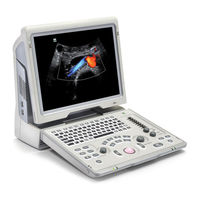
mindray Z6Vet Service Manual (179 pages)
Diagnostic Ultrasound System
Brand:
mindray
| Category:
Medical Equipment
| Size: 6 MB
Table of Contents
Table of Contents
3
Appendix A ELECTRICAL SAFETY INSPECTION
7
Revision History
7
Intellectual Property Statement
8
Applicable for
8
Statement
8
Responsibility on the Manufacturer Party
8
Customer Service Department
9
1 Preface
11
Meaning of Signal Words
11
Meaning of Symbols
11
Meaning of Safety Symbols
11
Warning Labels
12
General Symbols
12
Safety Precautions
13
Electric Safety
14
Mechanical Safety
14
Personnel Safety
15
Other
15
2 Product Specifications
17
Overview
17
Intended Use
17
Introduction of each Unit
17
Peripherals Supported
23
Specifications
24
Dimensions and Weight
24
Electrical Specifications
24
Environmental Conditions
24
Monitor Specification
24
3 System Installation
25
Preparations for Installation
25
Electrical Requirements
25
Installation Condition
26
Unpacking
26
Unpacking
27
Checking
29
Installation of Main Unit
29
Installing Battery
29
Control Panel Adjusting
30
Display Adjusting
30
Installing Probe Holder
31
Connecting a Probe
31
Installing Peripherals
32
Video Printer Installation
32
Installing a Graph / Text Printer
33
Installing External DVD-R/W
33
Installing Barcode Scanner
34
System Configuration
35
Power on / off
35
Enter Doppler
35
System Preset
36
Print Preset
38
Network Preset
40
System Information
42
4 Hardware Principle
45
General Structure of Hardware System
45
Main Unit
46
Probe Board
47
Main Board
48
IO Broad
51
Ultrasound System Monitor
52
Ultrasound System Indicator
53
Display
54
Control Panel
55
Power System
56
Power Output of the Power Supply Module and Supporting Function Distribution
56
System Power-On Control
57
5 Function and Performance Checking Method
61
Instruction
61
Checking System Status
61
System Running Status
61
General Exam
62
Check Flow
62
Checking Content
62
Function Checks
64
Check Flow
64
Checking Content
65
Performance Test
71
Test Process
71
Test Content
71
6 Software Upgrade and Maintenance
77
Enter the Maintenance Window
77
System Software Installation/ Restoration
78
Restore the Operating System and Doppler
78
Doppler Restoration
82
Installation of Optional Devices
86
Data Backup and Storage
87
Manage Settings
87
Patient Data Backup and Restore
87
Software Maintenance
88
Product Configuration
88
Log Maintenance
89
Display Parameter Setting
90
HDD Partition
91
7 Structure and Assembly/Disassembly
95
Structure of the Complete System
95
Field Replaceable Unit
96
Preparations
105
Tools Required
105
Engineers Required
105
Assembly/Disassembly Required
105
Assembly/Disassembly
105
Battery Connecting Board
106
Power Supply Module
108
IO Broad
111
Probe Board
112
Main Board and CPU Module
113
Top Cover Assembly of Keyboard
115
Display Assembly
119
Hard Disk
123
Speaker
124
8 System Diagnosis and Support
129
General Status Indicator
129
Status Indicators of the Control Panel
129
Status Indicator of the Power Supply on the IO Board
130
Status of Whole Machine
130
Starting Process of the Whole System
131
Start Process of Complete System
131
Start-Up Process of BIOS
132
Start-Up of Linux
133
Start-Up of Doppler
134
Alarming and Abnormal Information
136
Turning on the System Configuration File Is Abnormal
137
The Voltage of System Power Is Abnormal
137
Temperature Alarming
137
Fan Alarming
138
Battery Alarming
138
PHV Related Alarming
139
9 Care and Maintenance
141
Overview
141
Tools, Measurement Devices and Consumables
141
Care and Maintenance Items
142
Cleaning
143
Clean the System
143
Clean the Peripherals
146
Checking
146
General Check
146
System Function Check
147
Peripherals and Options Check
148
Mechanical Safety Inspection
148
Electrical Safety Inspection
149
10 Troubleshooting of Regular Malfunctions
151
System Cannot be Powered on
151
Module or Board Related
151
Key Points Supporting Troubleshooting
151
Troubleshooting
151
System Cannot Start up Normally
152
Module or Board Related
152
Key Points Supporting Troubleshooting
152
Troubleshooting
152
Image Fault
153
Module or Board Related
153
Key Points Supporting Troubleshooting
154
Troubleshooting
154
Probe Socket System Malfunction
154
Module or Board Related
154
Key Points Supporting Troubleshooting
155
Troubleshooting
155
IO Interface System
155
Module or Board Related
155
Key Points Supporting Troubleshooting
156
Troubleshooting
156
Control Panel
156
Module or Board Related
156
Key Points Supporting Troubleshooting
157
Troubleshooting
157
LCD Display
158
Module or Board Related
158
Key Points Supporting Troubleshooting
158
Troubleshooting
158
Electrical Safety Inspection
160
Appendix B Phantom Usage Illustration
176
Advertisement
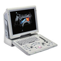
Mindray Z6Vet Service Manual (173 pages)
Diagnostic Ultrasound System
Brand:
Mindray
| Category:
Medical Equipment
| Size: 7 MB
Table of Contents
Table of Contents
3
Revision History
7
Intellectual Property Statement
7
Applicable for
7
Statement
8
Customer Service Department
8
Preface
9
Meaning of Signal Words
9
Meaning of Symbols
9
Meaning of Safety Symbols
9
Warning Labels
10
General Symbols
10
Safety Precautions
12
Electric Safety
12
Mechanical Safety
13
Personnel Safety
13
Other
13
Product Specifications
15
Overview
15
Intended Use
15
Introduction of each Unit
15
Peripherals Supported
21
Specifications
22
Dimensions and Weight
22
Electrical Specifications
22
Environmental Conditions
22
Monitor Specification
22
System Installation
23
Preparations for Installation
23
Electrical Requirements
23
Installation Condition
24
Unpacking
24
Unpacking
25
Checking
27
Installation of Main Unit
27
Installing Battery
27
Control Panel Adjusting
27
Display Adjusting
28
Installing Probe Holder
29
Connecting a Probe
29
Installing Peripherals
30
Video Printer Installation
30
Installing a Graph / Text Printer
31
Installing External DVD-R/W
31
System Configuration
32
Power on / off
32
Enter Doppler
32
System Preset
33
Print Preset
35
Network Preset
37
System Information
40
Hardware Principle
41
General Structure of Hardware System
41
Main Unit
42
Probe Board
42
Main Board
43
IO Broad
45
Drive Board
46
Ultrasound System Monitor
47
Ultrasound System Indicator
48
Display
49
Control Panel
50
Power System
51
Power Output of the Power Supply Module and Supporting Function Distribution
51
System Power-On Control
52
Function and Performance Checking Method
55
Instruction
55
Checking System Status
55
System Running Status
55
General Exam
56
Check Flow
56
Checking Content
56
Function Checks
58
Check Flow
59
Checking Content
59
Performance Test
66
Test Process
66
Test Content
66
Software Upgrade and Maintenance
73
Enter the Maintenance Window
73
System Software Installation/ Restoration
74
Installation of Optional Devices
74
Data Backup and Storage
77
Manage Settings
77
Patient Data Backup and Restore
78
Software Maintenance
79
Product Configuration
79
Log Maintenance
79
Display Parameter Setting
81
HDD Partition
82
Structure and Assembly/Disassembly
85
Structure of the Complete System
85
Field Replaceable Unit
86
Preparations
97
Tools Required
97
Engineers Required
97
Assembly/Disassembly Required
97
Assembly/Disassembly
97
Battery Connecting Board
98
Power Supply Module
100
IO Broad
103
Probe Board
104
Main Board and CPU Module
105
Top Cover Assembly of Keyboard
107
Display Assembly
111
Hard Disk
115
Speaker
116
System Diagnosis and Support
121
General Status Indicator
121
Status Indicators of the Control Panel
121
Status Indicator of the Power Supply on the IO Board
122
Status of Whole Machine
122
Starting Process of the Whole System
123
Start Process of Complete System
124
Start-Up Process of BIOS
125
Start-Up of Linux
125
Start-Up of Doppler
126
Alarming and Abnormal Information
128
Turning on the System Configuration File Is Abnormal
129
The Voltage of System Power Is Abnormal
129
Temperature Alarming
129
Fan Alarming
130
Battery Alarming
130
PHV Related Alarming
131
Care and Maintenance
133
Overview
133
Tools, Measurement Devices and Consumables
133
Care and Maintenance Items
134
Cleaning
135
Clean the System
135
Clean the Peripherals
138
Checking
138
General Check
138
System Function Check
139
Peripherals and Options Check
140
Mechanical Safety Inspection
140
Electrical Safety Inspection
141
Troubleshooting of Regular Malfunctions
143
System Cannot be Powered on
143
Module or Board Related
143
Key Points Supporting Troubleshooting
143
Troubleshooting
143
System Cannot Start up Normally
144
Module or Board Related
144
Key Points Supporting Troubleshooting
144
Troubleshooting
144
Image Fault
145
Module or Board Related
145
Key Points Supporting Troubleshooting
146
Troubleshooting
146
Probe Socket System Malfunction
147
Module or Board Related
147
Key Points Supporting Troubleshooting
147
Troubleshooting
147
IO Interface System
148
Module or Board Related
148
Key Points Supporting Troubleshooting
148
Troubleshooting
148
Control Panel
149
Module or Board Related
149
Key Points Supporting Troubleshooting
149
Troubleshooting
149
LCD Display
150
Module or Board Related
150
Key Points Supporting Troubleshooting
150
Troubleshooting
150
Electrical Safety Inspection
154
Appendix B Phantom Usage Illustration
169
Advertisement
Related Products
mindray Z6
mindray Z6T
mindray Z6S
mindray Z6W
Mindray Z6 Pro
Mindray Z60W
mindray Z5
mindray Z5Vet
Mindray Z50
Mindray Z50BW
mindray Categories
Medical Equipment
Diagnostic Equipment
Measuring Instruments
Monitor
Water Pump
More mindray Manuals
Login
Sign In
OR
Sign in with Facebook
Sign in with Google
Upload manual
Upload from disk
Upload from URL