Sign In
Upload
Manuals
Brands
Mindray Manuals
Medical Equipment
Resona 7
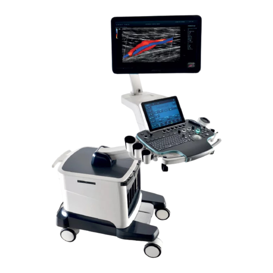
Mindray Resona 7 Ultrasound System Manuals
Manuals and User Guides for Mindray Resona 7 Ultrasound System. We have
5
Mindray Resona 7 Ultrasound System manuals available for free PDF download: Operator's Manual, Service Manual
Mindray Resona 7 Operator's Manual (492 pages)
Diagnostic Ultrasound System
Brand:
Mindray
| Category:
Medical Equipment
| Size: 50 MB
Table of Contents
Table of Contents
3
Intellectual Property Statement
15
Responsibility on the Manufacturer Party
15
Warranty
16
Important Information
16
About this Manual
17
Safety Precautions
21
Meaning of Safety Symbols
21
Safety Precautions
22
Latex Alert
28
System Overview
29
Intended Use
29
Contraindication
29
Safety Classifications
29
Product Specifications
30
Power Supply
30
Environmental Conditions
30
Dimensions and Weight
31
Product Differences
31
System Configuration
32
Standard Configuration
32
Probes and Needle-Guided Brackets Available
32
Options
32
Peripherals Supported
36
Parts that Can be Used Within Patient Environment
37
Introduction of each Unit
37
I/O Panel
39
Power Supply Panel
40
Physio Unit Panel (ECG)
41
Control Panel
42
Keyboard
44
Basic Screen & Operation
46
Monitor Display
46
Dialog Box
47
Menu Operation
48
The Display of Touch Screen and Its Operation
49
Warning Labels
51
Symbols
52
System Preparation
55
Moving/Positioning the System
55
Connecting the Power Cord
56
Connecting Power
56
Equipotential Terminal
56
Powering ON/OFF
57
Checking before Powering on
57
Powering the System on
57
Checking after Powering on
58
Powering the System off
59
Standby
59
Adjusting Monitor Position
60
Adjusting Height and Displacement
60
Rotating the Monitor
61
Tilting the Monitor
61
Locking the Monitor
61
Adjusting Monitor Brightness/Contrast
62
Adjusting the Control Panel Position
62
Connecting/Disconnecting a Probe
63
Connecting a Probe
63
Disconnecting a Probe
64
Installing a Probe Adapter
64
Connecting Peripheral Devices
66
Connecting USB Devices
66
Connecting a Footswitch
66
Connecting a Graph/Text Printer
67
Connecting a Video Printer
68
Connecting a Wireless Printer
68
Rectangle Caps
69
Installing Storage Tray Kit
69
Setup
73
System Preset
73
Region
74
General
74
Image Preset
76
Application
77
Key Configuration
82
Gesture
82
Output
83
Access Control
83
Scan Code
86
Key Probe
89
Biopsy
89
Exam Mode Preset
89
Measurement Preset
90
General Measurement Preset
90
Application Measurement Preset
92
Report Preset
98
Comment Preset
101
Comment Configure
101
Comment Group Define
101
Iworks Preset
102
Protocol Management
102
View Management
102
Create a New Protocol
102
Stress Echo Preset
103
Protocol Edit
103
Maintenance
104
Dicom/Hl7
104
DICOM Local Preset
104
DICOM Service Preset
106
Network Preset
112
Network Settings
112
Istorage Preset
113
Medtouch/Medsight Preset
114
Q-Path Preset
114
Print Preset
114
Print Setting
114
Image Settings
115
Maintenance
115
Exporting Setup Data
115
Importing Setup Data
115
Load Factory
115
Probe Check
116
Other Settings
116
Security
116
Drive Encryption/Secure Data Wipe
116
Anti-Virus
117
System Information
117
Exam Preparation
119
Patient Information
119
New Patient Information
119
Retrieve Patient Information
122
Select Exam Mode and Probe
123
Dual-Probe Switch
124
Bi-Plane Probe Switch
124
Selecting Imaging Mode
124
Activate& Continue an Exam
124
Activate an Exam
124
Continue an Exam
124
Pause & End an Exam
125
Pause an Exam
125
End an Exam
125
Image Acquisition
127
Imaging Mode
127
Image Adjustment
127
Quickly Saving Image Settings
129
B Mode
129
B-Mode Image Scanning
129
B-Mode Image Parameters
130
Color Mode
133
Color Mode Image Scanning
134
Color Mode Image Parameters
134
Power Mode
137
Power Mode Image Scanning
137
Power Mode Image Parameters
138
Flow
138
Basic Operations
139
Image Optimization
140
Vector Flow Quantitative Analysis
141
Volume Flow Calculation
144
WSS (Wall Shear Stress)
145
M Mode
146
M Mode Image Scanning
147
M Mode Image Parameters
147
Color M Mode (CM)
148
CM Image Scanning
148
CM Image Parameters
148
Anatomical M Mode
149
Free Xros M
149
Free Xros CM (Curved Anatomical M-Mode)
149
Anatomical M Mode Parameters
150
PW/CW Mode
150
PW/CW Mode Image Scanning
151
PW/CW Mode Image Parameters
151
Tdi
154
TDI Mode Image Scanning
154
TDI Mode Image Parameters
155
TDI Quantitative Analysis
156
Iscape View
158
Basic Procedures
159
Image Review
160
Evaluate Image Quality
160
Cine Review
161
R-Vqs
161
RIMT (Real-Time Intima-Media Thickness)
163
Tissue Tracking Quantitative Analysis
164
Basic Procedures for Tissue Tracking QA
164
Screen Display of Tissue Tracking QA
165
Select Image and Cardiac Cycle
166
Myocardial Boundary Tracing
167
Basic Operations of TTQA
168
Bulleye
169
Measurement/Comment
169
Data Export
169
Fusion Imaging
170
Overview
170
Magnetic Navigator
170
Screen Description
175
Basic Procedures
176
Acquiring/Importing Volume Data
180
Marks
182
Respiratory Compensation
185
Freehand 3D
188
Parameter Settings
188
Rotating/Scrolling Ct/Mr/Pet/Freehand Image
190
Measuring
191
Comment and Body Mark
191
Smart Fetal HR (Heart Rate)
191
Ipage
192
Iworks (Auto Workflow Protocol)
193
Screen Display
194
View Operation
194
Manual Examination
195
Insert
195
Create
195
Overview
197
Terms
197
ROI and VOI
198
About the Probes
199
Mpr
199
Free View
200
Wire Cage
200
Orientation Assistance
200
Note before Use
201
Static 3D
203
Basic Procedures for Static 3D Imaging
203
Static 3D Acquisition Preparation
204
Static 3D Image Viewing
205
Color 3D
212
Basic Procedures for Color 3D
212
Operation Controls
212
Procedures
213
Acquisition Preparation
214
Image Review
214
Smart 3D
214
Smart 3D Procedures
214
Smart 3D Acquisition Preparation
215
STIC (Spatio-Temporal Image Correlation)
215
Ilive
217
Layout
219
Reference Point
219
Print Format
220
Smart Volume
220
Basic Procedure
221
Result Display
222
Operation Controls
223
Ipage
224
Operating Procedures
224
Basic Screen & Operation
225
Scv
228
Basic Procedures
228
Operation Controls
229
Smart Planes CNS
230
Basic Procedures for Smart Planes CNS
231
Smart ICV
233
Other Operations
234
Smart FLC (Smart Follicles Calculation)
235
Basic Procedures
235
Operation Controls
236
Smart Planes FH (Smart Planes on Fetal Heart)
236
Basic Procedures
236
Operation Controls
237
Smart Face
237
Parameter Adjusting
237
Volume CEUS
238
Smart Scene 3D
239
Elastography
241
Strain Elastography
241
Basic Procedure for Strain Elastography
241
Image Parameters
241
Mass Measurement
243
Cine Review
243
STE Imaging (Sound Touch Elastography)
243
Basic Procedures for STE Imaging
243
Image Parameters
244
STE-Hiremeasuring
246
Cine Review
246
PZ Tracking (Peripheral Zone Tracking)
247
STQ Imaging (Sound Touch Quantification)
247
Basic Procedures for the STQ Imaging
247
Image Parameters
248
M-Ref. E Compare
250
E Compare (Non Real Time)
251
E Compare Live (Real Time)
252
Image Parameters
253
M-Ref. E Biopsy
253
Contrast Imaging
255
Basic Procedures for Contrast Imaging
255
Left Ventricular Opacification
256
Image Parameters
256
Micro Flow Enhancement
258
Contrast Imaging QA
258
M-Ref. C&E
261
Physiological Unit Signal
265
Ecg
266
ECG Triggering
266
ECG Review
267
Respiratory Wave
267
Pcg
268
PCG Operation Basic Procedures
268
PCG Sensor Cleaning
269
Parameter Description
269
Stress Echo
271
Stress Echo Acquisition Procedure
271
Selecting Preferred Stress Echo Loops (Select Mode)
272
Review/Wms Mode
274
Enter Review Mode
274
Wall Motion Scoring
275
Saving Stress Echo Data
276
Exiting the Stress Echo Feature
276
Measurement and Report
276
Smart Pelvic Floor (Smart Pelvic)
277
Two Dimensional Image
277
4D Image Data
278
Display & Cine Review
281
Splitting Display
281
Image Magnification
281
Res Zoom
281
Pan Zoom
282
Spot Zoom
282
Izoom (Full-Screen Zooming)
282
Freeze/Unfreeze the Image
282
Cine Review
283
Advertisement
Mindray Resona 7 Service Manual (365 pages)
Diagnostic Ultrasound System
Brand:
Mindray
| Category:
Diagnostic Equipment
| Size: 31 MB
Table of Contents
Table of Contents
3
Revision History
9
Intellectual Property Statement
10
Applicable for
10
Statement
10
Responsibility on the Manufacturer Party
11
Service Contact
11
Safety Precautions
13
Meaning of Signal Words
13
Symbols
13
Meaning of Safety Symbols
13
Warning Labels
14
General Symbols
14
Safety Precautions
16
Electric Safety
16
Mechanical Safety
17
Personnel Safety
17
Other
17
Specifications
19
Overview
19
Intended Use
19
Introduction of each Unit
19
Peripherals Supported
28
Specifications
28
Dimensions & Weight
28
Electrical Specifications
28
Environmental Conditions
29
Monitor Specification
29
System Installation
31
Preparations for Installation
31
Electrical Requirements
31
Installation Conditions
32
Confirmation before Installation
33
Unpacking
33
Unpacking Process
33
Checking
36
Bare Machine Transport
37
Tool
37
Device Transport
38
Fixing Methods
38
Installing Main Unit
41
Opening up the Monitor
41
Connecting the Power Cord
41
Connecting ECG
42
Installing Probe Holder
42
Installing Gel Holder
42
Connecting the Transducer
44
Installing Peripherals
45
Connecting a Footswitch
45
Installing a Graph/Text Printer
45
Installing a Video Printer
48
Installing a Wireless Printer
49
Installing the Printer Driver in Windows Interface
49
Installing a Barcode Scanner
51
Ascending/Descending the Main Control Panel Manually
52
System Configuration
55
Running the System
55
Entering Doppler
55
System Preset
56
Printer Preset
57
Network Preset
58
Network Configuration
59
DICOM/HL7 Preset
62
Security
64
Check System Information
65
Product Principle
67
General Structure of Hardware System
67
Ultrasound Front Unit
68
Probe Board
69
TR Board
70
Engine Board
71
ECG Module
72
TEE Board
73
Ultrasound Back-End Unit
73
COME (CPU) Module
74
Independent GPU (GPU)
74
Memory Device (SSD&SATA Hard Disk)
74
PC Carrier Board
74
User I/O Interface Board
82
Wifi Module
83
Power Supply Unit
83
AC Interface Module
83
Auxiliary Output Power Isolation Transformer
84
AC-DC Module
84
DC-DC Board
84
PHV Module
84
Battery Management Board and Battery Module
85
New Power Supply Unit
86
AC-DC Module
87
To 24V Control Board
87
DC-DC Board
87
PHV Module
87
Battery Module
87
User Interaction Unit
87
Control Panel
87
Primary Display Assembly
88
Secondary Display Assembly
88
Electrical Ascending/Descending and Electromagnet
89
Function and Performance Checking Method
91
Note
91
Device Status Checking
91
Running Status
91
Working Condition
91
General Exam
92
Check Flow
92
Checking Content
92
Function Checking
94
Check Flow
95
Performance Test
101
Test Process
101
Test Content
101
Software Installation &Maintenance
109
Entering Maintenance
109
Set Installment
109
Software Installation/Restoration
112
Enter Windows
112
Software Maintenance
113
Export Log
113
Log Manager
113
Activating Operating System
115
Data Backup and Storage
118
Preset Data Management
118
Patient Data Backup and Restoration
119
Probe Check
119
Introduction on Hard Disk's Partitions
120
Adjustments
121
Adjusting Monitor
121
Adjusting Position
121
Adjusting Brightness and Contrast
124
Monitor Test
125
Touch Screen Adjustment
126
Touch Screen Brightness and Contrast Adjustment
126
Touch Screen Test
126
Control Panel Adjustment
127
Adjusting Caster
127
Field Replaceable Unit
129
Explosive View
130
Assembly Explosive View
131
Monitor Assembly (A0)
131
Monitor Support Arm Assembly (B0)
134
Main Control Panel Assembly (C0)
136
Control Panel Support Arm Assembly (D0)
144
Main Unit Assembly (E0)
147
Base Assembly (F0)
154
Base Power Box Assembly (G0)
155
Cable (H0)
157
Fusion Imaging Assembly (I0)
160
Structure and Assembly/Disassembly
163
Structure of the Complete System
163
Preparation
164
Tools Required
164
Engineers Required
164
Requirements
164
Assembly/Disassembly
165
Large/Small Probe Holders, Left Bracket of Coupling Gel Heating Cup, Intracavitary Probe Holder
167
Cup Rack Assembly
168
Wire Pothook Assembly
168
Mesh of the Base
169
Display (Monitor) Assembly
169
Control Panel Assembly
171
Handle Panel Assembly
182
Touch Screen Assembly
183
Speaker Cover Assembly
184
Left/Right Speaker Assembly
185
Upper/Lower Support Arm Cover
185
Support Arm Assembly
186
LCD Signal Connector PCBA Assembly
193
Control Panel Moving Mechanism Assembly
197
Main Unit Rear Cover Assembly
201
Mindray Resona 7 Service Manual (359 pages)
Diagnostic Ultrasound System
Brand:
Mindray
| Category:
Diagnostic Equipment
| Size: 31 MB
Table of Contents
Table of Contents
3
Revision History
9
Intellectual Property Statement
10
Applicable for
10
Statement
10
Responsibility on the Manufacturer Party
11
Service Contact
11
Safety Precautions
13
Meaning of Signal Words
13
Symbols
13
Meaning of Safety Symbols
13
Warning Labels
14
General Symbols
14
Safety Precautions
16
Electric Safety
16
Mechanical Safety
17
Personnel Safety
17
Other
17
Specifications
19
Overview
19
Intended Use
19
Introduction of each Unit
19
Peripherals Supported
26
Specifications
26
Dimensions & Weight
26
Electrical Specifications
27
Environmental Conditions
27
Monitor Specification
28
System Installation
29
Preparations for Installation
29
Electrical Requirements
29
Installation Conditions
30
Confirmation before Installation
31
Unpacking
31
Unpacking Process
31
Checking
34
Bare Machine Transport
35
Tool
35
Device Transport
36
Fixing Methods
36
Installing Main Unit
39
Opening up the Monitor
39
Connecting the Power Cord
39
Connecting ECG
40
Installing Probe Holder
40
Installing Gel Holder
40
Connecting the Transducer
42
Installing Peripherals
43
Connecting a Footswitch
43
Installing a Graph/Text Printer
43
Installing a Video Printer
46
Installing a Wireless Printer
47
Installing the Printer Driver in Windows Interface
47
Installing a Barcode Scanner
49
Ascending/Descending the Main Control Panel Manually
50
System Configuration
53
Running the System
53
Entering Doppler
53
System Preset
54
Printer Preset
55
Network Preset
56
Network Configuration
57
DICOM/HL7 Preset
60
Security
62
Check System Information
63
Product Principle
65
General Structure of Hardware System
65
Ultrasound Front Unit
66
Probe Board
67
TR Board
68
Engine Board
69
ECG Module
70
TEE Board
71
Ultrasound Back-End Unit
71
COME (CPU) Module
72
Independent GPU (GPU)
72
Memory Device (SSD&SATA Hard Disk)
72
PC Carrier Board
72
User I/O Interface Board
80
Wifi Module
81
Power Supply Unit
81
AC Interface Module
81
Auxiliary Output Power Isolation Transformer
82
AC-DC Module
82
DC-DC Board
82
PHV Module
82
Battery Management Board and Battery Module
83
New Power Supply Unit
84
AC-DC Module
85
To 24V Control Board
85
DC-DC Board
85
PHV Module
85
Battery Module
85
User Interaction Unit
85
Control Panel
85
Primary Display Assembly
86
Secondary Display Assembly
86
Electrical Ascending/Descending and Electromagnet
87
Function and Performance Checking Method
89
Note
89
Device Status Checking
89
Running Status
89
Working Condition
89
General Exam
90
Check Flow
90
Checking Content
90
Function Checking
92
Check Flow
93
Performance Test
99
Test Process
99
Test Content
99
Software Installation &Maintenance
107
Entering Maintenance
107
Set Installment
107
Software Installation/Restoration
110
Enter Windows
110
Software Maintenance
111
Export Log
111
Log Manager
111
Fast Startup
113
Activating Operating System
113
Data Backup and Storage
116
Preset Data Management
116
Patient Data Backup and Restoration
117
Probe Check
117
Introduction on Hard Disk's Partitions
118
Adjustments
119
Adjusting Monitor
119
Adjusting Position
119
Adjusting Brightness and Contrast
120
Monitor Test
121
Touch Screen Adjustment
122
Touch Screen Brightness and Contrast Adjustment
122
Touch Screen Test
122
Control Panel Adjustment
123
Adjusting Caster
123
Field Replaceable Unit
125
Explosive View
126
Assembly Explosive View
127
Monitor Assembly (A0)
127
Monitor Support Arm Assembly (B0)
131
Main Control Panel Assembly (C0)
133
Control Panel Support Arm Assembly (D0)
141
Main Unit Assembly (E0)
144
Base Assembly (F0)
151
Base Power Box Assembly (G0)
152
Cable (H0)
154
Fusion Imaging Assembly (I0)
157
Structure and Assembly/Disassembly
159
Structure of the Complete System
159
Preparation
160
Tools Required
160
Engineers Required
160
Requirements
160
Assembly/Disassembly
161
Large/Small Probe Holders, Left Bracket of Coupling Gel Heating Cup, Intracavitary Probe Holder
163
Cup Rack Assembly
164
Wire Pothook Assembly
164
Mesh of the Base
165
Display (Monitor) Assembly
165
Control Panel Assembly
167
Handle Panel Assembly
178
Touch Screen Assembly
179
Speaker Cover Assembly
180
Left/Right Speaker Assembly
181
Upper/Lower Support Arm Cover
181
Support Arm Assembly
182
LCD Signal Connector PCBA Assembly
187
Bale of Wire for the Monitor/Side Control Panel Base/Base Assembly
188
Control Panel Moving Mechanism Assembly
190
Main Unit Rear Cover Assembly
195
Advertisement
Mindray Resona 7 Operator's Manual (451 pages)
Diagnostic Ultrasound System
Brand:
Mindray
| Category:
Medical Equipment
| Size: 16 MB
Table of Contents
Table of Contents
3
Intellectual Property Statement
7
Responsibility on the Manufacturer Party
7
Warranty
8
Important Information
10
About this Manual
10
Notation Conventions
10
Operator's Manuals
11
Hardcopy Manuals
11
Software Interfaces in this Manual
11
Conventions
12
1 Safety Precautions
13
Safety Classification
13
Meaning of Signal Words
14
Meaning of Safety Symbols
14
Safety Precautions
15
Warning Labels
23
2 System Overview
25
Intended Use
25
Contraindication
25
Product Specifications
25
System Configuration
27
Ultrasound Gel Heater
30
Introduction of each Unit
33
I/O Panel
35
Power Supply Panel
36
Physio Unit Panel (ECG)
37
Control Panel
38
Symbols
42
3 System Preparation
43
Moving/Position the System
43
Connecting Power Cord & Protective Grounding
44
Monitor Adjustment
48
Control Panel Position Adjustment
50
Connecting/Disconnecting a Probe
50
Connecting Peripheral Devices
52
Basic Screen & Operation
57
4 Exam Preparation
67
Patient Information
67
Select Exam Mode and Probe
74
Selecting Imaging Mode
75
Activate& Continue an Exam
75
Pause & Continue an Exam
76
5 Image Optimization
77
Imaging Mode
77
B-Mode Image Optimizing
79
M Mode Image Optimization
86
Color Mode Image Optimization
88
Power Mode Image Optimization
94
Flow
95
PW/CW Mode Optimization
104
Color M Mode (CM)
110
Free Xros M Mode
111
Tdi
113
D/4D
117
Iscape
158
Contrast Imaging
161
Elastography
168
Stress Echo
180
Tissue Tracking Quantitative Analysis
188
Fusion Imaging
195
RIMT (Real-Time Intima-Media Thickness)
220
R-Vqs
221
Smart Pelvic Floor
223
6 Display & Cine Review
225
Splitting Display
225
Image Magnification
225
Freeze/Unfreeze the Image
226
Cine Review
227
Image Compare
229
Cine Saving
230
Preset
230
7 Physiological Unit Signal
233
Ecg
234
Pcg
235
ECG/PCG Review
237
Respiratory Wave
237
Parameter Description
238
8 Measurement
239
Basic Operations
239
General Measurements
240
Application Measurements
242
Measurement Accuracy
242
9 Comments and Body Mark
245
Comments
245
Voice Comments
250
Body Mark
251
Mindray Resona 7 Service Manual (339 pages)
Brand:
Mindray
| Category:
Medical Equipment
| Size: 19 MB
Table of Contents
Table of Contents
3
Revision History
9
Intellectual Property Statement
10
Applicable for
10
Statement
10
Responsibility on the Manufacturer Party
11
Customer Service Department
11
1 Safety Precautions
13
Meaning of Signal Words
13
Symbols
13
Meaning of Safety Symbols
13
Warning Labels
14
General Symbols
14
Safety Precautions
16
Electric Safety
16
Mechanical Safety
17
Personnel Safety
17
Other
17
2 Specifications
19
Overview
19
Intended Use
19
Introduction of each Unit
19
Peripherals Supported
27
Specifications
27
Dimensions & Weight
27
Electrical Specifications
27
Environmental Conditions
28
Monitor Specification
28
3 System Installation
29
Preparations for Installation
29
Electrical Requirements
29
Installation Conditions
30
Confirmation before Installation
31
Unpacking
31
Unpacking Process
31
Checking
34
Bare Machine Transport
35
Tool
35
Device Transport
36
Fixing Methods
36
Installing Main Unit
39
Opening up the Monitor
39
Connecting the Power Cord
39
Connecting ECG
40
Installing Probe Holder
40
Installing Gel Holder
40
Connecting the Transducer
42
Installing Peripherals
43
Connecting a Footswitch
43
Installing a Graph / Laser Printer
44
Installing Video Printer
46
Installing a Wireless Printer
47
Installing a Barcode Scanner
48
Ascending/Descending the Main Control Panel Manually
49
System Configuration
52
Running the System
52
Entering Doppler
52
System Preset
53
Printer Preset
54
Network Preset
55
DICOM/HL7 Preset
56
Check System Information
57
4 Product Principle
59
General Structure of Hardware System
59
Ultrasound Front Unit
60
Probe Board
61
TR Board
62
Engine Board
63
ECG Module
64
TEE Board
65
Ultrasound Back-End Unit
65
COME (CPU) Module
66
Independent GPU (GPU)
66
Memory Device (SSD&SATA Hard Disk)
66
PC Carrier Board
66
User I/O Interface Board
74
Wifi Module
75
Power Supply Unit
75
AC Interface Module
75
Auxiliary Output Power Isolation Transformer
76
AC-DC Module
76
DC-DC Board
76
PHV Module
76
New Power Supply Unit
77
AC-DC Module
78
To 24V Control Board
78
DC-DC Board
78
PHV Module
78
User Interaction Unit
79
Control Panel
79
Primary Display Assembly
80
Secondary Display Assembly
80
Electrical Ascending/Descending and Electromagnet
81
5 Function and Performance Checking Method
83
Note
83
Device Status Checking
83
Running Status
83
Working Condition
83
General Exam
84
Check Flow
84
Checking Content
84
Function Checking
86
Check Flow
87
Basic Measurements
91
Performance Test
93
Test Process
93
Test Content
93
6 Software Installation &Maintenance
101
Entering Maintenance
101
Set Installment
101
Software Installation/Restoration
104
Enter Windows
104
Software Maintenance
105
Export Log
105
Data Backup and Storage
105
Preset Data Management
105
Patient Data Backup and Restoration
106
Introduction on Hard Disk's Partitions
107
7 Adjustments
109
Adjusting Monitor
109
Adjusting Position
109
Adjusting Brightness and Contrast
111
Monitor Test
111
Touch Screen Adjustment
114
Touch Screen Brightness and Contrast Adjustment
114
Touch Screen Test
114
Control Panel Adjustment
115
Adjusting Caster
115
8 Field Replaceable Unit
117
9 Structure and Assembly/Disassembly
145
Structure of the Complete System
145
Preparation
146
Tools Required
146
Engineers Required
146
Requirements
146
Assembly/Disassembly
147
Large/Small Probe Holders, Left Bracket of Coupling Gel Heating Cup, Intracavitary Probe
148
Holder
148
Cup Rack Assembly
149
Wire Pothook Assembly
150
Mesh of the Base
150
Display (Monitor) Assembly
151
Control Panel Assembly
153
Handle Panel Assembly
164
Touch Screen Assembly
164
Speaker Cover Assembly
166
Left/Right Speaker Assembly
167
Upper/Lower Support Arm Cover
167
Support Arm Assembly
168
LCD Signal Connector PCBA Assembly
169
Support Arm Spanner/Bale of Wire for the Monitor/Side Control Panel Base/Base Assembly
170
Control Panel Moving Mechanism Assembly
173
Main Unit Rear Cover Assembly
178
Main Unit Left Cover Assembly
178
Main Unit Right Cover Assembly
179
Main Unit Front-Top Cover Assembly
180
Turbine Cover
181
Turbine Protective Shell Assembly
181
Main Unit Top Cover/Main Unit Top Cover Assembly
182
Right/Left Brake Pedal
183
Machine Assembly
184
PC Main Board Assembly
191
Wireless Net Adapter
195
Antenna and Cable Assembly
196
IO Assembly
197
Probe Board Assembly
198
Electronics Assembly on the Base
199
HDD Assembly
207
DVD Assembly
208
Front Output Panel
210
ECG Assembly
212
Signal Cable of ECG Module
212
Mother Board Assembly
213
Housing Assembly of the Main Unit
216
Magnetic Generator Trolley
232
Magnetic Navigator
235
Advertisement
Related Products
Mindray Resona Y
Mindray Resona I9 Easi
Mindray Resona I9 Nasa
Mindray Resona IV
Mindray Resona N9
Mindray Resona I9 Exp Resona I9S
Mindray Resona IY
Mindray Resona I8 Easi
Mindray Recho R9 Pro
Mindray Recho R9T
Mindray Categories
Medical Equipment
Diagnostic Equipment
Measuring Instruments
Monitor
Water Pump
More Mindray Manuals
Login
Sign In
OR
Sign in with Facebook
Sign in with Google
Upload manual
Upload from disk
Upload from URL