Sign In
Upload
Manuals
Brands
Mindray Manuals
Measuring Instruments
BC-5000 VET
Mindray BC-5000 VET Manuals
Manuals and User Guides for Mindray BC-5000 VET. We have
1
Mindray BC-5000 VET manual available for free PDF download: Service Manual
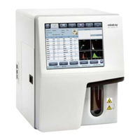
Mindray BC-5000 VET Service Manual (244 pages)
AUTO HEMATOLOGY ANALYZER
Brand:
Mindray
| Category:
Measuring Instruments
| Size: 7 MB
Table of Contents
Intellectual Property Statement
2
Repair Service
3
Return Procedure
3
Table of Contents
5
Overview
12
Who Should Read this Manual
12
How to Find Information
12
Conventions Used in this Manual
13
Special Terms Used in this Manual
13
Symbol
15
Specifications
18
Product Name
18
Physical Specifications
18
Electrical Specifications
18
Environment Requirements
19
Specifications
19
Testing Parameters
19
Performance Requirements
20
Background/Blank Count
20
Carryover
20
Linearity Range
22
Display Range
22
Product Description
23
Main Unit
25
Power/Status Indicator
25
Power Switch
25
[Aspirate] Key
25
USB Port
26
Product Configuration
26
Reagents, Controls and Calibrators
26
Reagents
26
Reagent Consumption Volume
27
Controls and Calibrators
27
Information Storage Capacity
27
Operation Principles
28
Overview
28
Workflow
28
Sample Aspiration
29
White Blood Cell Measurement
29
Laser Flow Cytometry
29
Hemoglobin Concentration Measurement
29
Colorimetric Method
29
Hemoglobin Concentration Parameters
30
Impedance Method
30
Time Measurement
31
Red Blood Cell Parameters
31
Platelet Parameters
32
Software and Interface
33
Start-Up
33
Version Check
33
Login
33
Log in Using Service Level Username and Password
33
Login Check
34
Review
36
Stability Trend Graph
36
Trend Graph
37
Calibration
37
Calibration Factor
37
Calibration
38
Sample Probe Debug
39
Temperature Calibration
39
Gain Calibration
40
Gain Setting
42
Gain Verification
43
Special Information
43
Performance
44
Background Test
44
Reproducibility
45
Carryover
46
Advance Toolbox
47
System Configuration
47
One-Key Export
47
Software Update
48
Status Indicator
49
Buzzer
50
Error Code
51
Data Transmission
52
LIS Connection
52
Communication Error
55
Communication Error Analysis
56
Physical Connection
56
Communication Setup
56
Network Firewall
56
Optical System
57
Introduction to the Principles of Optical System
57
Operation Principles
57
Beam Path of the Optical System
58
Physical Structure
58
Overall Structure
58
Light Source Assembly
60
Flow Cell Assembly
60
Optical Substrate Assembly
61
Preamplifier and Shield Shell
61
Shield Shell Assembly
62
Scattering Detection Assembly
62
Laser Control Board
63
Determining the Optical System Status
63
Maintenance and Replacement of the Optical System
65
Maintenance of the Optical System
65
Replacement of the Optical System
70
Fluidics
72
Measurement Flow
72
WBC&HGB Channel
73
RBC/PLT Channel
75
Sample Volume
75
Temperature of Fluidics
76
Reagent Consumption Volume
76
Introduction to Fluidic Parts
76
Mindray Valves
76
2-Way Mindray Pressure-Proof Valve
77
LVM Fluidic Valve
78
Pinch Valve
78
Liquid Filter
79
Syringe Linkage
80
Electromagnetic Metering Pump
80
Preheat Bath
81
Vacuum Pump
82
Sample Probe
83
Probe Wipes
83
Hydraulic Pressure Sensor
84
1-Way Valve
85
Baths
85
Detailed Introduction of Fluidic Structure
85
Sampling and Dispensing Channel
86
WBC&HGB Channel
86
RBC/PLT Channel
88
Precautions for Assembly and Service
89
Introduction to Sequences
91
Measurement Sequence in WB-CBC+DIFF Mode
91
Measurement Sequence in PD Mode
104
Introduction to the Maintenance Sequences
104
Startup Cleaning
105
Hardware System
107
Hardware System Overview
107
Functional Block Diagram
107
Master Control
107
Electrical Connection Block Diagram
108
System Troubleshooting
108
Digital Control Board
110
Overview
110
Components
110
Adjustment and Tests
114
Troubleshooting
117
Analog Drive Board
121
Overview
121
Components
121
Sockets and Indicators
125
Troubleshooting
129
Power Board
132
Overview
132
Replacement and Connection
133
Troubleshooting
134
Optical Boards
134
Optical Path and Optical System Workflow
134
Functions of Optical Boards
135
Troubleshooting
137
Touchscreen Drive Board
139
Overview
139
Components
139
Troubleshooting
139
Indicator Board
140
Overview
140
Components
141
Troubleshooting
141
Motor, Photocoupler and Microswitch
142
Overview
142
Troubleshooting
142
Liquid Sensor Board
143
Overview
143
Composition
143
Troubleshooting
143
Heating System
144
Heating System Overview
144
Diluent Heating System
144
Optical Heating System
146
Mechanical System
147
Mechanical System Overview
147
Front View
147
Back View
148
Left View
150
Components
151
Introduction
151
Overall
152
Exploded View
152
Parts List
152
Main Unit
153
Panel Module (VET)
157
Syringe Assembly
158
Sample Probe Assembly
159
RBC Count Pool Module
160
HGB Count Pool Module
161
Pump Assembly
162
Power Backplane Assembly
162
Optical System
164
Power Assembly
165
Removal and Installation
165
Tools
165
Preparation for Disassembly
165
Disassembling the Main Unit
166
Removing the Back Plate
167
Removing the Analog Drive Board PCBA
167
Removing the Pinaster Board or the SD Card
168
Removing the Power Backplate Assembly
169
Removing the Fan Assembly
170
Removing the Right Panel
170
Removing the RBC Count Pool Module(FRU)
171
Installation
172
Removing the Ruby Red Cell Counter(D50Um)
172
Removing the HGB Amp Module
173
Removing the Liquid Detect Board PCBA
175
Removing the Reagent Bottle Plate Cosmetic Piece
175
Removing the Preheat Assembly
176
Removing the Electromagnet Pinch Valve Assembly
177
Removing the Right Valve Assembly
178
Removing the Pump
179
Removing the Vacuum Chamber Assembly
180
Removing the Top Cover
180
18Removing the Temperature Detection Assembly
181
Removing the Sampling Probe Assembly
181
Replace the Vertical Motor of the Sampling Probe Assembly
183
Removing the Probe Wipe
183
Replacing the Sample Probe
184
Removing the Syringe Motor Position Sensor
185
Removing the Transducer Discreteness
186
Removing the Panel Module
187
Removing the Indicator Board PCBA
187
Removing the 6301 Touch Control Board PCBA
188
Removing the LCD Module
189
Removing the Touch Panel
190
Removing the Microswitch Assembly
190
Removing the Syringe
191
Removing the Syringe Motor
192
Removing the Syringe Motor Position Sensor Assembly
193
Removing the Liquid Detect Assembly
193
Front Panel
194
Removing the Left Door Assembly
195
Removing the Optical System
196
Removing the Optical System Cover
196
Replacing the RBC/WBC Isolation Chamber Filter
196
Replacing the Power Board PCBA
197
Troubleshooting
199
Troubleshooting Procedure
199
Debug
221
Mechanical Position Adjustment
221
Commissioning of Detection Elements
222
Calibrate and Verify the Preheat Temperature
222
Counting Channel Measurement
223
Commissioning and Verification after Servicing
226
Service BOM
231
Appendices
234
Fluidic Diagram
234
Hardware Block Diagram
239
Cables and Wires
240
Appendix Table
241
Connection and Tube
242
Advertisement
Advertisement
Related Products
Mindray BC-2800
Mindray BC-3000 Plus
Mindray BC-5380
Mindray BC-1800
Mindray BC-20s
Mindray BC-30s
Mindray BS-120
Mindray BS-130
Mindray BS-190
Mindray BS-200
Mindray Categories
Medical Equipment
Diagnostic Equipment
Measuring Instruments
Monitor
Water Pump
More Mindray Manuals
Login
Sign In
OR
Sign in with Facebook
Sign in with Google
Upload manual
Upload from disk
Upload from URL