Miller Millermatic 251 Manuals
Manuals and User Guides for Miller Millermatic 251. We have 3 Miller Millermatic 251 manuals available for free PDF download: Technical Manual, Owner's Manual

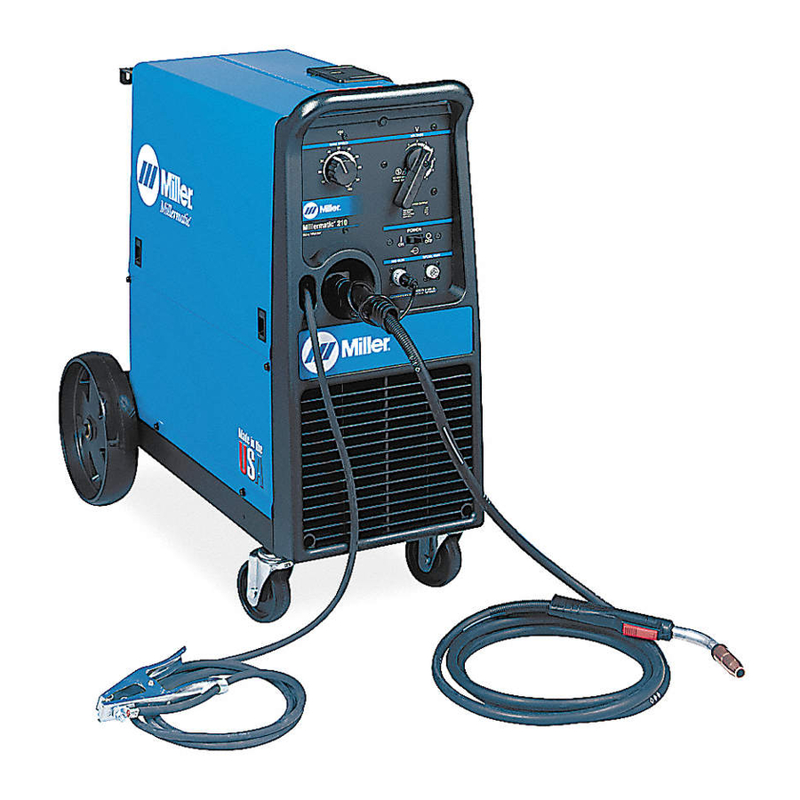
Miller Millermatic 251 Owner's Manual (56 pages)
Arc Welding Power Source and Wire Feeder
Brand: Miller
|
Category: Welding System
|
Size: 2 MB
Table of Contents
Advertisement

Miller Millermatic 251 Owner's Manual (56 pages)
Arc Welding Power Source and Wire Feeder
Brand: Miller
|
Category: Welding System
|
Size: 1 MB
Table of Contents

Miller Millermatic 251 Technical Manual (72 pages)
Welding Range 30 to 300 Amps
Brand: Miller
|
Category: Welding System
|
Size: 3 MB
Table of Contents
Advertisement
Advertisement