Sign In
Upload
Manuals
Brands
Miller Electric Manuals
Welding System
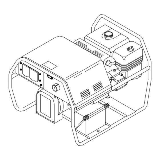
BLUE STAR 6000 TM-499C
Miller Electric BLUE STAR 6000 TM-499C Manuals
Manuals and User Guides for Miller Electric BLUE STAR 6000 TM-499C. We have
1
Miller Electric BLUE STAR 6000 TM-499C manual available for free PDF download: Technical Manual
Miller Electric BLUE STAR 6000 TM-499C Technical Manual (80 pages)
Miller Electric Welding System User Manual
Brand:
Miller Electric
| Category:
Welding System
| Size: 3 MB
Table of Contents
Table of Contents
2
Section 1 − Safety Precautions for Servicing
5
Symbol Usage
5
Servicing Hazards
5
California Proposition 65 Warnings
6
EMF Information
6
Section 2 − Definitions
7
Symbol Definitions
7
Section 3 − Specifications
7
Weld, Power, and Engine Specifications
7
Dimensions, Weights, and Operating Angles
8
Fuel Consumption (Kohler-Powered Units)
8
Fuel Consumption (Honda-Powered Units)
9
Duty Cycle
9
Generator Power Curves
10
Volt-Ampere Curves
11
Section 4 − Installation
12
Installing Welding Generator
12
Grounding Generator to Truck or Trailer Frame
12
Grounding Generator When Supplying Building Systems
13
Engine Prestart Checks (Kohler-Powered Units)
13
Engine Prestart Checks (Honda-Powered Units)
14
Connecting the Battery (Electric-Start Models Only)
14
Connecting to Weld Output Terminals
15
Selecting Weld Cable Sizes
15
Section 5 − Operating the Welding Generator
16
Controls (Kohler-Powered Units)
16
Controls (Honda-Powered Units) (See Section 5-3)
17
Description of Controls (Honda-Powered Units) (See Section 5-2)
18
Section 6 − Operating Auxiliary Equipment
19
Generator Power Panel 495 218 (USA)
19
Optional Generator Power Panels
20
Generator Power Panel Ratings
21
Wiring Instructions for Optional 120/240 Volt Twistlock Plug (NEMA L14-30P)
22
Section 7 − Maintenance
22
Maintenance Label
22
Routine Maintenance
23
Overload Protection (Honda-Powered Units)
24
Adjusting Engine Speed (Kohler-Powered Units)
24
Adjusting Engine Speed (Honda-Powered Units)
25
Section 8 − Theory of Operation
26
Section 9 − Explanation of Electrical Parts
28
Section 10 − Troubleshooting
35
Troubleshooting Tables
35
Troubleshooting Circuit Diagram for Welding Generator (Use with Section 10-3)
40
Test Points and Values (Use with Section 10-2)
42
Waveforms for Section
43
Control Board PC1 Testing Information
44
Control Board PC1 Test Point Values
45
Replacing Brushes and Cleaning Slip Rings
46
Checking Unit Output after Servicing
47
Section 11 − Disassembly and Reassembly
48
Disassembly of Unit
48
Removing Rotor and Reassembling Generator
49
Section 12 − Electrical Diagrams
50
Section 13 − Parts List for La124002 Thru Lb111747 (Kohler Only)
58
Section 14 − Parts List for Lb111748 Thru Lc061260 (Kohler) and Lb086216 Thru Lc061260 (Honda)
62
Section 15 − Parts List for Lc061261 Thru Lc552236 (Kohler & Honda)
68
Section 16 − Parts List for Lc552237 and Following
74
Advertisement
Advertisement
Related Products
Miller Electric 602
Miller Electric Dimension 652
Miller Electric Spectrum 625
Miller Electric Auto Axcess 675
Miller Electric Big Blue 602P
Miller Electric Big Blue 602DR
Miller Electric Big Blue 600D
Miller Electric MOG-Pak 6A
Miller Electric MOG-Pak 6APR
Miller Electric 600 X
Miller Electric Categories
Welding System
Welding Accessories
Inverter
Controller
Utility Vehicle
More Miller Electric Manuals
Login
Sign In
OR
Sign in with Facebook
Sign in with Google
Upload manual
Upload from disk
Upload from URL