Sign In
Upload
Manuals
Brands
Miller Manuals
Welding System
Big Blue 450 Duo CST
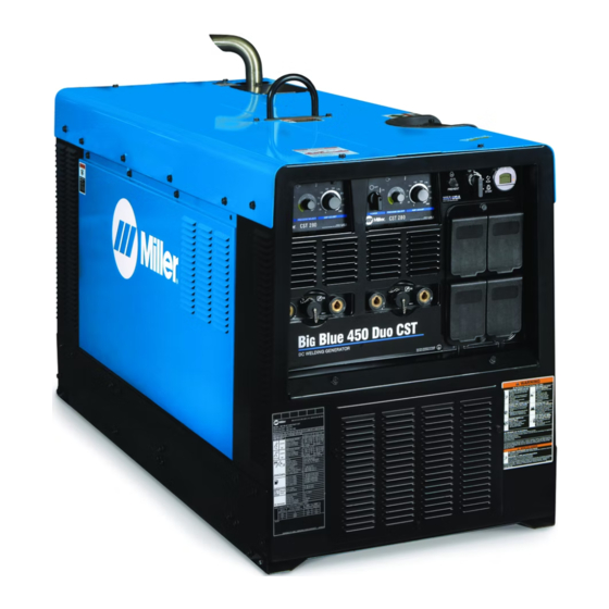
Miller Big Blue 450 Duo CST Manuals
Manuals and User Guides for Miller Big Blue 450 Duo CST. We have
3
Miller Big Blue 450 Duo CST manuals available for free PDF download: Owner's Manual
Miller Big Blue 450 Duo CST Owner's Manual (76 pages)
Brand:
Miller
| Category:
Welding System
| Size: 2 MB
Table of Contents
Table of Contents
3
Section 1 − Safety Precautions − Read before Using
5
Symbol Usage
5
Arc Welding Hazards
5
Engine Hazards
7
Compressed Air Hazards
7
Additional Symbols for Installation, Operation, and Maintenance
8
California Proposition 65 Warnings
10
Principal Safety Standards
10
EMF Information
10
Section 2 − Consignes de Sécurité − Lire Avant Utilisation
11
Signification des Symboles
11
Dangers Relatifs au Soudage à L'arc
11
Dangers Existant en Relation Avec le Moteur
13
Dangers Liés à L'air Comprimé
14
Dangers Supplémentaires en Relation Avec L'installation, le Fonctionnement et la Maintenance
15
Proposition Californienne 65 Avertissements
17
Principales Normes de Sécurité
17
Informations Relatives aux CEM
17
Section 3 − Definitions
18
Wordless Label Definitions
18
Warning Label Definitions
19
Symbols and Definitions
20
Section 4 − Specifications
21
Weld, Power, and Engine Specifications
21
Dimensions, Weights, and Operating Angles
21
Duty Cycle
22
Fuel Consumption
22
Volt-Ampere Curves
23
AC Generator Power Curve
24
Section 5 − Installation
25
Serial Number and Rating Label Locations
25
Installing Welding Generator
25
Mounting Welding Generator
26
Grounding Generator to Truck or Trailer Frame
27
Installing Exhaust Pipe
27
Connecting the Battery
28
Engine Prestart Checks
29
Selecting Weld Cable Sizes
30
Making Dual Operator CC Weld Connections with Common Work Cables
31
Paralleling CST Units for SMAW Welding
32
Section 6 − Operation
33
Front Panel Engine Controls (See Section 6-2)
33
Description of Front Panel Engine Controls (See Section 6-1)
33
Operating Optional Engine Block Heater
34
Fuel/Hour Gauge Descriptions
35
Front Panel CST Controls
36
Section 7 − Operating Auxiliary Equipment
38
Generator Power Receptacles
38
Export Auxiliary Power Receptacles
39
GFCI Receptacle Information, Resetting and Testing
40
Section 8 − Maintenance & Troubleshooting
41
Maintenance Label
41
Routine Maintenance
42
Cleaning Unit
42
Servicing Air Cleaner
43
Checking Generator Brushes
43
Inspecting and Cleaning Spark Arrestor Muffler
44
Servicing Engine Cooling System
44
Servicing Fuel and Lubrication Systems
45
Overload Protection
46
Adjusting Engine Speed
46
Troubleshooting CST
47
Troubleshooting Generator
48
Section 9 − Electrical Diagrams
50
Section 10 − Run-In Procedure
52
Wetstacking
52
Run-In Procedure Using Load Bank
53
Run-In Procedure Using Resistance Grid
54
Section 11 − Generator Power Guidelines
55
Section 12 − Parts List
62
Options and Accessories
76
Advertisement
Miller Big Blue 450 Duo CST Owner's Manual (68 pages)
Brand:
Miller
| Category:
Welding System
| Size: 8 MB
Table of Contents
Table of Contents
3
Section 1 - Safety Precautions - Read before Using
5
Symbol Usage
5
Arc Welding Hazards
5
Engine Hazards
7
Compressed Air Hazards
8
Additional Hazards for Installation, Operation, and Maintenance
8
California Proposition 65 Warnings
10
Principal Safety Standards
10
EMF Information
10
Section 2 - Consignes de Sécurité - Lire Avant Utilisation
11
Symboles Utilisés
11
Dangers Relatifs au Soudage à L'arc
11
Dangers Existant en Relation Avec le Moteur
13
Dangers Liés à L'air Comprimé
14
Symboles de Dangers Supplémentaires en Relation Avec L'installation, le Fonctionnement et la Maintenance
15
Proposition Californienne 65 Avertissements
17
Principales Normes de Sécurité
17
Informations Relatives aux CEM
17
Section 3 - Definitions
19
Additional Safety Symbol Definitions
19
Miscellaneous Symbols and Definitions
22
Section 4 - Specifications
24
Serial Number and Rating Label Locations
24
Software Licensing Agreement
24
Information about Default Weld Parameters and Settings
24
Weld, Power, and Engine Specifications
24
Dimensions, Weights, and Operating Angles
24
Environmental Specifications
25
Duty Cycle and Overheating
25
Volt-Ampere Curves: Stick
26
Volt-Ampere Curves: TIG
27
AC Generator Power Curve
27
Fuel Consumption
27
Section 5 - Installation
28
Installing Welder/Generator
28
Grounding Generator to Truck or Trailer Frame
29
Installing Exhaust Pipe
29
Connecting the Battery
30
Engine General Information
30
Engine Fuel and Coolant Prestart Information
31
Mitsubishi Engine Oil Prestart Information
32
Selecting Cable Sizes
32
Weld Output Terminals
33
Making Dual Operator CC Weld Connections with Common Work Cables
34
Paralleling CST Units for SMAW Welding
35
Section 6 - Operation
36
Front Panel Engine Controls
36
Operating Optional Engine Block Heater
37
Fuel/Hour Gauge Descriptions
38
Front Panel CST Controls
39
Section 7 - Operating Auxiliary Equipment
41
Generator Power Receptacles
41
GFCI Receptacle Information, Resetting, and Testing
42
Section 8 - Maintenance and Troubleshooting
43
Maintenance Label
43
Routine Maintenance
44
Cleaning Unit
45
Servicing Air Cleaner
46
Battery Maintenance
46
Checking Generator Brush Assembly
47
Inspecting and Cleaning Optional Spark Arrestor Muffler
47
Servicing Engine Cooling System
48
Adjusting Engine Speed
48
Servicing Fuel and Lubrication Systems
49
Overload Protection
50
Troubleshooting CST
51
Troubleshooting Generator
53
Section 9 - Parts List
55
Recommended Spare Parts
55
Section 10 - Electrical Diagrams
56
Section 11 - Run-In Procedure
58
Wetstacking
58
Run-In Procedure Using Load Bank or Resistance Grid
59
Section 12 - Generator Power Guidelines
60
Miller Big Blue 450 Duo CST Owner's Manual (64 pages)
Engine Driven Welder/Generator
Brand:
Miller
| Category:
Welding System
| Size: 2 MB
Table of Contents
Table of Contents
3
Section 1 − Safety Precautions − Read before Using
5
Symbol Usage
5
Arc Welding Hazards
5
Engine Hazards
7
Compressed Air Hazards
7
Additional Symbols for Installation, Operation, and Maintenance
8
California Proposition 65 Warnings
10
Principal Safety Standards
10
EMF Information
10
Section 2 − Consignes de Sécurité − Lire Avant Utilisation
11
Signification des Symboles
11
Dangers Relatifs Au Soudage À L'arc
11
Dangers Existant en Relation Avec Le Moteur
13
Dangers Liés À L'air Comprimé
14
Dangers Supplémentaires en Relation Avec L'installation, Le Fonctionnement Et la Maintenance
15
Proposition Californienne 65 Avertissements
17
Principales Normes de Sécurité
17
Informations Relatives Aux CEM
17
Section 3 − Definitions
19
Additional Safety Symbols and Definitions
19
Symbols and Definitions
20
Section 4 − Specifications
21
Serial Number and Rating Label Locations
21
Weld, Power, and Engine Specifications
21
Dimensions, Weights, and Operating Angles
21
Environmental Specifications
22
Tier 4 Final Engine (Domestic Models) Performance Curves
22
Section 5 − Installation
25
Installing Welder/Generator
25
Installing Exhaust Pipe
26
Connecting the Battery
27
Engine General Information
27
Engine Fuel and Coolant Prestart Information
28
Mitsubishi Engine Oil Prestart Information
28
Selecting Cable Sizes
29
Weld Output Terminals
29
Making Dual Operator CC Weld Connections with Common Work Cables
30
Paralleling CST Units for SMAW Welding
31
Section 6 − Operation
32
Front Panel Engine Controls (See Section 6-2)
32
Description of Front Panel Engine Controls (See Section 6-1)
32
Operating Optional Engine Block Heater
33
Fuel/Hour Gauge Descriptions
34
Front Panel CST Controls
35
Section 7 − Operating Auxiliary Equipment
37
Generator Power Receptacles
37
GFCI Receptacle Information, Resetting, and Testing
38
Section 8 − Maintenance & Troubleshooting
39
Maintenance Label
39
Routine Maintenance
40
Cleaning Unit
40
Servicing Air Cleaner
41
Battery Maintenance
42
Checking Generator Brushes
42
Inspecting and Cleaning Spark Arrestor Muffler
42
Servicing Engine Cooling System
43
Adjusting Engine Speed
43
Servicing Fuel and Lubrication Systems
44
Overload Protection
45
Troubleshooting CST
46
Troubleshooting Generator
47
Section 9 − Parts List
49
Recommended Spare Parts
49
Section 10 − Electrical Diagrams
50
Section 11 − Run-In Procedure
52
Wetstacking
52
Run-In Procedure Using Load Bank or Resistance Grid
53
Section 12 − Generator Power Guidelines
54
Advertisement
Advertisement
Related Products
Miller Big Blue 400 CX CE
Miller Big Blue 400 Pro
Miller Big Blue 400 PipePro
Miller Big Blue 400 PX CE
Miller Big Blue 400 Eco Pro CC
Miller Big Blue 800 DUO PRO
Miller Big Blue 300 P
Miller Big Blue 500 X
Miller Big Blue 350 PipePro
Miller Big Blue 600 Air Pak
Miller Categories
Welding System
Welding Accessories
Camera Accessories
Portable Generator
Motorcycle Accessories
More Miller Manuals
Login
Sign In
OR
Sign in with Facebook
Sign in with Google
Upload manual
Upload from disk
Upload from URL