Sign In
Upload
Manuals
Brands
Micronor Manuals
Controller
MR340-1
Micronor MR340-1 Manuals
Manuals and User Guides for Micronor MR340-1. We have
1
Micronor MR340-1 manual available for free PDF download: Instruction Manual
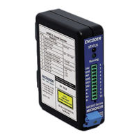
Micronor MR340-1 Instruction Manual (74 pages)
Fiber Optic Incremental Encoder DIN Rail Mount Controller
Brand:
Micronor
| Category:
Controller
| Size: 5 MB
Table of Contents
Revision History
2
Table of Contents
3
Product Description
6
Incremental Encoder Background
6
Fiber Optic Incremental Sensor
6
Figure 1. MR340 Series Fiber Optic Encoder System Family
6
Figure 2. Typical MR340 Encoder System Connections to User's Motion Control System
7
Initial Preparation
8
Unpacking and Inspection
8
Damage in Shipment
8
Standard Contents
8
Warranty Information
9
Installation and Operation
10
Mounting the Sensor Unit
10
Figure 4. Keep LC Duplex Connector Ends Protected When Not in Use
10
Mounting the MR340-1 Controller Module
11
Figure 5. Mounting Controller to 35Mm DIN Rail
11
Figure 6. Mounting Controller to Wall Using Screws
11
Optical Connections to the Controller
12
Figure 7. Connecting Sensor to Controller Optical Interface
12
3.3.1 Cleaning Fiber Optic Connections
13
Figure 8. Clean Receptacle with the Supplied Cleaning Stick
13
Figure 9. Clean Optical Plug with Supplied Clean Wipes
13
Electrical Connections to Controller
14
Main Electrical Connections
14
Figure 10. Typical MR340 Encoder Sensor System Connections to Motion Control System
14
Interfacing with a Motor Drive
15
Figure 11. J1-Connector Pin Assignments
15
SSI and RS485 Interface Connections (J3)
16
Figure 13. Location of SSI, Rs485/Modbus RTU, and USB Connections
16
Figure 14. J3-Connector Pin Assignments
16
Figure 15. Hirose Plug for J3-Connector
16
USB Interface (J2)
17
Programmable Analog Output - Current or Voltage Connections
17
Figure 16. Connection for 4-20Ma Current Loop
17
Figure 17. Connection for Voltage Output
18
How to Install the MR343 Linear Encoder
19
Film Mounting and Handling with MR343
19
Figure 18. Positioning Film Inside MR343 Sensor
19
Figure 19. TD5334 Encoder Filmstrip Dimensions
20
Initial Optical Power Level Referencing When Using Film
21
Figure 20. Location of Internal CAL Button for Initial Optical Level Calibration
21
Indexing for Linear Absolute Position
22
Power-Up or Periodic Optical Sensitivity Calibration
23
Optical Sensistivity Calibration for Linear Sensors
23
Optical Sensititivty Calibration for Rotary Sensors
23
Initial System Configuration and Power-Up Examples
24
Rotary Encoder Configuration and Operation
24
Linear Encoder with Film and Using HOMING Function
26
Linear Encoder with Film Without HOMING Region
28
Modbus Serial Communications
30
Modbus Serial Interface
30
MODBUS Communications Protocol
32
Detailed Description of each Function
40
Counter (Register 0X001)
40
Speed /RPM Output (Register 0X003)
40
Voltage Mode (Register 0X200)
41
Voltage Scale (Register 0X201)
42
Voltage Filter (Register 0X203)
43
Current Mode (Register 0X204)
44
Current Scale (Register 0X205)
47
Current Filter (Register 0X207)
47
Counter Reset Mode (Register 0X208)
48
Counter Reset (Register 0X209)
49
Quadrature Edge Multiplier (Register 0X211)
49
Turn Direction (Register 0X20B)
50
Line Driver Output Voltage (Register 0X214)
51
Analog Output Select (Register 0X215)
51
Eeprom Set (Fc05-2)
52
Error Handling and Troubleshooting
53
Explanation of Status and Error Handling
53
Explanation of Status and Error Indication
53
Reading the Error Counters
58
Specifications
59
MR340-1 DIN Rail Mount Controller
59
MR343 Linear Sensor
60
Zappy® 302 Software
61
How to Install and Use Zappy® 302
61
ZAPPY® Menu Screens
61
System Functions Screen
61
Figure 21. ZAPPY® System Functions Screen
62
User Functions Screen
63
Figure 22. ZAPPY® User Functions Screen
63
Service Functions Screen
64
Figure 23. ZAPPY® Service Functions Screen
64
Command List Screen
65
Figure 24. ZAPPY® Command List Screen
65
MR340 Theory of Operation
66
Figure 25. Block Diagram of MR340-1 Controller
66
MR340-1 Reprogramming the Firmware
68
DAMAGED Firmware Recovery
71
Mechanical Reference Drawings
72
MR340-1 Controller
72
MR343 Linear Sensor
72
Advertisement
Advertisement
Related Products
Micronor MR380-1 Series
Micronor MR380-2 Series
Micronor MR380-1-3
Micronor MR380-0
Micronor MR380-0-UNI
Micronor MR332
Micronor MR361 Series
Micronor MR380 Series
Micronor MR318
Micronor MR328
Micronor Categories
Controller
Media Converter
Switch
Air Conditioner
Accessories
More Micronor Manuals
Login
Sign In
OR
Sign in with Facebook
Sign in with Google
Upload manual
Upload from disk
Upload from URL