Sign In
Upload
Manuals
Brands
MG Manuals
Measuring Instruments
47 Series
MG 47 Series Manuals
Manuals and User Guides for MG 47 Series. We have
4
MG 47 Series manuals available for free PDF download: Operating Manual
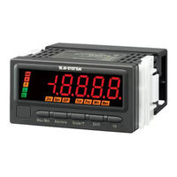
MG 47 Series Operating Manual (114 pages)
FREQUENCY INPUT DIGITAL PANEL METER(4 1/2 digit, LED display type)
Brand:
MG
| Category:
Measuring Instruments
| Size: 30 MB
Table of Contents
Table of Contents
2
Introduction
5
Before Use
5
SAFETY PRECAUTIONS (that Must be Observed)
6
Points of Caution
8
Component Identification
10
Installation
14
External Dimensions
14
Panel Cutout Dimensions
14
Installation
15
Wiring Instructions
17
Caution in Wiring
17
Recommended Solderless Terminal
17
Terminal Assignment
17
Wiring Input Signal
18
Wiring DC Output
19
Wiring Alarm Output
19
Wiring Power
20
Installing/Separating Terminal Block
21
Attaching/Removing Terminal Cover
21
Basic Setting and Operation
23
Basic Setting
23
Basic Setting Flow
23
Relation Among Input Type, Input Scaling and Display Scaling
23
Basic Setting Procedure
24
Basic Setting Operation and Instructions
25
Basic Setting Operation
25
Instructions on Basic Operation
27
Setting Input Type
28
Input Type List
29
Operating Procedure
29
Setting Scaling Values
31
Step 1. Input Scaling Value a
33
Input Scaling List
33
Operating Procedure
34
Step 2. Display Scaling Value a
37
Display Scaling List
37
Operating Procedure
38
Step 3. Input Scaling Value B
41
Operating Procedure
41
Step 4. Display Scaling Value B
44
Operating Procedure
44
Step 5. Decimal Point Position
47
Decimal Point Position List
47
Operating Procedure
48
Operation
51
Parameter Configuration
52
Setting Analog Output Function
57
Operating Procedure
58
Setting Alarm Output
59
Alarm Point
62
Operating Procedure
62
Alarm Setpoint
64
Alarm Setpoint List
64
Operating Procedure
64
Trip Action (Lo/Hi)
67
Operating Procedure
67
Deadband
69
Operating Procedure
69
On Delay Time
71
Operating Procedure
71
ALARM OUTPUT LOGIC (Coil Energized or De-Energized at Alarm)
73
Operating Procedure
73
Main Display Blinking at Alarm
75
Operating Procedure
75
Adjusting Brightness of Display
77
Operating Procedure
78
Going Back Automatically to Measuring Mode
79
Operating Procedure
80
Adjusting Display Refreshing Rate
82
Operating Procedure
83
Loop Testing
85
Loop Test Output Range
85
Operating Procedure
86
Useful Functions
88
Confirming Alarm Setpoints
88
Retaining Max and Min Values
89
Limiting Button Operation
91
Operating Procedure
91
Transition Time to Lockout Setting Mode
93
Operating Procedure
93
User Calibration
95
Analog Output Adjustment
95
Analog Output Adjustment Flow
95
Operating Procedure
96
Inspection / Cleaning
99
Troubleshooting
100
Error Messages
100
Initializing Setting Values
100
Operating Procedure
100
Confirming Firmware Version
102
Operating Procedure
102
Appendices
103
Specifications
103
Input Specifications
104
Model Numbering
106
Alarm Output
106
Parameter List
107
Parameter Map
109
Operation in Measuring Mode
109
Scaling Setting Mode
110
Alarm Setting Mode
111
Advanced Setting Mode
112
Lockout Setting Mode
113
Loop Test Output Mode
113
Character Set
114
Advertisement
MG 47 Series Operating Manual (109 pages)
RTD INPUT DIGITAL PANEL METER(4 digit, LED display type)
Brand:
MG
| Category:
Measuring Instruments
| Size: 27 MB
Table of Contents
Table of Contents
2
Introduction
5
Before Use
5
SAFETY PRECAUTIONS (that Must be Observed)
6
Points of Caution
8
Component Identification
10
Installation
14
External Dimensions
14
Panel Cutout Dimensions
14
Installation
15
Wiring Instructions
17
Caution in Wiring
17
Recommended Solderless Terminal
17
Terminal Assignment
17
Wiring Input Signal
18
Wiring DC Output
18
Wiring Alarm Output
19
Wiring Power
20
Installing/Separating Terminal Block
21
Attaching/Removing Terminal Cover
21
Basic Setting and Operation
23
Basic Setting
23
Basic Setting Flow
23
Basic Setting Procedure
23
Basic Setting Operation and Instructions
25
Basic Setting Operation
25
Instructions on Basic Operation
26
Setting Input Type
27
Input Type List
27
Operating Procedure
28
Setting Temperature Unit
30
Operating Procedure
30
Setting Decimal Point Position
33
Operating Procedure
33
Operation
36
Parameter Configuration
37
Setting Analog Output
43
Analog Output Setting Range
43
Operating Procedure
44
Setting Alarm Output
46
Alarm Point
49
Operating Procedure
49
Alarm Setpoint
51
Alarm Setpoint Default Value
51
Alarm Setpoint List
51
Operating Procedure
52
Trip Action (Lo/Hi)
54
Operating Procedure
54
Deadband
56
Operating Procedure
56
On Delay Time
58
Operating Procedure
58
ALARM OUTPUT LOGIC (Coil Energized or De-Energized at Alarm)
60
Operating Procedure
60
Main Display Blinking at Alarm
62
Operating Procedure
62
Averaging Input
64
Operating Procedure
65
Adjusting Brightness of Display
66
Operating Procedure
67
Going Back Automatically to Measuring Mode
69
Operating Procedure
70
Setting Burnout
72
Operating Procedure
72
Adjusting Display Refreshing Rate
74
Operating Procedure
75
Loop Testing
77
Loop Test Output Range
77
Operating Procedure
78
Useful Functions
80
Confirming Alarm Setpoints
80
Retaining Max and Min Values
81
Limiting Button Operation
83
Operating Procedure
83
Transition Time to Lockout Setting Mode
85
Operating Procedure
85
User Calibration
87
Input Compensation
87
Input Compensation Flow
87
Operating Procedure
88
Analog Output Adjustment
90
Analog Output Adjustment Flow
90
Operating Procedure
91
Inspection / Cleaning
94
Troubleshooting
95
Error Messages
95
Initializing Setting Values
95
Operating Procedure
95
Confirming Firmware Version
97
Operating Procedure
97
Appendices
98
Specifications
98
Input Specifications
99
Model Numbering
101
Alarm Output
101
Parameter List
102
Parameter Map
104
Operation in Measuring Mode
104
Initial Setting Mode
105
Alarm Setting Mode
106
Advanced Setting Mode
107
Lockout Setting Mode
108
Loop Test Output Mode
108
Character Set
109
MG 47 Series Operating Manual (106 pages)
THERMOCOUPLE INPUT DIGITAL PANEL METER (4 digit, LED display type)
Brand:
MG
| Category:
Measuring Instruments
| Size: 27 MB
Table of Contents
Table of Contents
2
Introduction
5
Before Use
5
SAFETY PRECAUTIONS (that Must be Observed)
6
Points of Caution
8
Component Identification
10
Installation
14
External Dimensions
14
Panel Cutout Dimensions
14
Installation
15
Wiring Instructions
17
Caution in Wiring
17
Recommended Solderless Terminal
17
Terminal Assignment
17
Wiring Input Signal
18
Wiring DC Output
19
Wiring Alarm Output
19
Wiring Power
20
Installing/Separating Terminal Block
21
Attaching/Removing Terminal Cover
21
Basic Setting and Operation
23
Basic Setting
23
Basic Setting Flow
23
Basic Setting Procedure
23
Basic Setting Operation and Instructions
24
Basic Setting Operation
24
Instructions on Basic Operation
25
Setting Input Type
26
Input Type List
26
Operating Procedure
27
Setting Temperature Unit
29
Operating Procedure
29
Operation
32
Parameter Configuration
33
Setting Analog Output
39
Analog Output Setting Range
39
Operating Procedure
40
Setting Alarm Output
42
Alarm Point
45
Operating Procedure
45
Alarm Setpoint
47
Alarm Setpoint Default Value
47
Alarm Setpoint List
47
Operating Procedure
48
Trip Action (Lo/Hi)
50
Operating Procedure
50
Deadband
52
Operating Procedure
52
On Delay Time
54
Operating Procedure
54
ALARM OUTPUT LOGIC (Coil Energized or De-Energized at Alarm)
56
Operating Procedure
56
Main Display Blinking at Alarm
58
Operating Procedure
58
Averaging Input
60
Operating Procedure
61
Adjusting Brightness of Display
62
Operating Procedure
63
Going Back Automatically to Measuring Mode
65
Operating Procedure
66
Setting Burnout
68
Operating Procedure
68
Setting Cold Junction Compensation (Cjc) Sensor
70
Operating Procedure
70
Adjusting Display Refreshing Rate
72
Operating Procedure
73
Loop Testing
75
Loop Test Output Range
75
Operating Procedure
76
Useful Functions
77
Confirming Alarm Setpoints
77
Retaining Max and Min Values
78
Limiting Button Operation
80
Operating Procedure
80
Transition Time to Lockout Setting Mode
82
Operating Procedure
82
User Calibration
84
Input Compensation
84
Input Compensation Flow
84
Operating Procedure
85
Analog Output Adjustment
87
Analog Output Adjustment Flow
87
Operating Procedure
88
Inspection / Cleaning
91
Troubleshooting
92
Error Messages
92
Initializing Setting Values
92
Operating Procedure
92
Confirming Firmware Version
94
Operating Procedure
94
Appendices
95
Specifications
95
Model Numbering
98
Alarm Output
98
Parameter List
99
Parameter Map
101
Operation in Measuring Mode
101
Initial Setting Mode
102
Alarm Setting Mode
103
Advanced Setting Mode
104
Lockout Setting Mode
105
Loop Test Output Mode
105
Character Set
106
Advertisement
MG 47 Series Operating Manual (81 pages)
DC INPUT DIGITAL PANEL METER (4 1/2 digit, process meter, LED display type)
Brand:
MG
| Category:
Measuring Instruments
| Size: 20 MB
Table of Contents
Table of Contents
2
Introduction
5
Before Use
5
SAFETY PRECAUTIONS (that Must be Observed)
6
Points of Caution
8
Component Identification
10
Installation
13
External Dimensions
13
Panel Cutout Dimensions
13
Installation
14
Wiring Instructions
16
Caution in Wiring
16
Recommended Solderless Terminal
16
Terminal Assignment
16
Wiring Input Signal
17
Wiring Power
18
Installing/Separating Terminal Block
19
Attaching/Removing Terminal Cover
19
Basic Setting and Operation
21
Basic Setting
21
Basic Setting Flow
21
Relation between Input Scaling and Display Scaling
21
Basic Setting Procedure
22
Basic Setting Operation and Instructions
23
Basic Setting Operation
23
Instructions on Basic Operation
25
Setting Scaling Values
26
Step 1. Input Scaling Value a
28
Input Scaling List
28
Operating Procedure
29
Step 2. Display Scaling Value a
31
Display Scaling List
31
Operating Procedure
32
Step 3. Input Scaling Value B
34
Operating Procedure
34
Step 4. Display Scaling Value B
36
Operating Procedure
36
Step 5. Decimal Point Position
38
Decimal Point Position List
38
Operating Procedure
39
Operation
41
Parameter Configuration
42
Averaging Input
45
Operating Procedure
46
Eliminating Fluctuation Around "0
47
Low-End Cutout
48
Operating Procedure
48
Low-End Cutout Value
50
Operating Procedure
50
Adjusting Brightness of Display
52
Operating Procedure
53
Going Back Automatically to Measuring Mode
55
Operating Procedure
56
Useful Functions
58
Forcing the Present Display Value to Zero
58
Retaining Max and Min Values
59
Limiting Button Operation
61
Operating Procedure
61
Transition Time to Lockout Setting Mode
63
Operating Procedure
63
User Calibration
65
Teach Calibration
65
Teach Calibration Flow
65
Operating Procedure
66
Inspection / Cleaning
68
Troubleshooting
69
Error Messages
69
Initializing Setting Values
69
Operating Procedure
69
Confirming Firmware Version
71
Operating Procedure
71
Appendices
72
Specifications
72
Model Numbering
74
Parameter List
75
Parameter Map
77
Operation in Measuring Mode
77
Scaling Setting Mode
78
Advanced Setting Mode
79
Lockout Setting Mode
80
Character Set
81
Advertisement
Related Products
MG 47LR
MG 47LHZ
MG 47NL Series
MG 47NLN
MG 47LYV
MG 47NLNT
MG 47NLDYT
MG 47NLRT
MG 47LT
MG 47NLR
MG Categories
I/O Systems
Control Unit
Transmitter
Automobile
Measuring Instruments
More MG Manuals
Login
Sign In
OR
Sign in with Facebook
Sign in with Google
Upload manual
Upload from disk
Upload from URL