Sign In
Upload
Manuals
Brands
Metretek Manuals
Modem
DCM-200
Metretek DCM-200 Manuals
Manuals and User Guides for Metretek DCM-200. We have
1
Metretek DCM-200 manual available for free PDF download: User Manual
Metretek DCM-200 User Manual (106 pages)
Metretek Digital Cellular Modem – 200
Brand:
Metretek
| Category:
Modem
| Size: 1 MB
Table of Contents
Table of Contents
6
1 Product Description
11
Product Overview
11
Communications Options
12
Communications Scenarios
14
CSD Versus Packet Mode
15
2 INSTALLATION and TECHNICAL INFORMATION
17
Unpacking, Damage Reports, Item List
17
Additional Items Required for Installation
17
Site Selection for Best Performance
18
Metretek Programmer Cable
18
Enclosure Dimensions
19
Enclosure Mounting Tab (1 of 4)
19
Mounting Tab Pattern
20
Conduit Entry Hole Pattern
20
Internal Components of the DCM-200
21
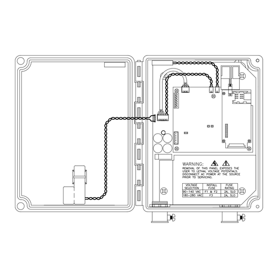
Internal View of the DCM-200 (Prior to 2006)
21
Serial Data Cable Wiring Connection
22
Terminal Block TB2 of the GUTC Board
22
To RJ-11 Adapter
22
Schematic of the RS-232 to RJ-11 Adapter
23
Installing the RS-232 to RJ-11 Adapter Board
24
Assembly of Data Cable Connector for Use with the Elster Alpha Meter
25
AC Power Cable Wiring Connection
26
Metal Safety Shield (Prior to 2006)
26
Metal Safety Shield (2006 and Later)
26
Routing and Connection of AC Mains Power (Prior to 2006)
27
Routing and Connection of AC Mains Power (2006 and Later)
27
AC Line Voltage Selection
28
Lithium Battery Pack Connection
28
Line Voltage Selection (Prior to 2006)
28
Battery Pack Connector (Prior to 2006)
29
Battery Pack Connector (2006 and Later)
29
Internal Antennas
30
1008-0012B-001Single-Band Antenna
30
1015-0208-001 Quad-Band Antenna
30
External Antennas
31
Installing the Quad-Band Antenna
31
External Antenna Connections
31
External Antenna Kits
32
3 Internal Circuit Boards
33
Power Supply Board
33
1001-0302 Power Supply Circuit Board (Prior to 2006)
33
Block Diagram of the 1001-0302 Power Supply Board
34
1001-0310 Power Supply Circuit Board (2006 and Later)
35
Block Diagram of the 1001-0310 Power Supply Board
36
GUTC Board
37
GUTC Circuit Board with G18 Radio
37
GUTC Circuit Board with G20 Radio
38
Block Diagram of the GUTC Board
39
Block Diagram of the DCM-200 System
39
GUTC Capacitor Board Installation
40
Top and Side View of Capacitor Board
40
Side View of Capacitor Board Installation
41
Top View of Capacitor Board Installation
42
4 Cellular Service
43
GSM Service
43
GSM Overview
43
Establishing Cellular Service for GPRS
43
Establishing Cellular Service for CSD
44
Requesting a Voice Phone Number or SMS Service
45
SIM Card Installation
45
SIM Card Profile
45
SIM Card Installation for the G18 Radio
46
Screw Positions for the GUTC Board
47
SIM Card Installation for the G20 Radio
48
5 Device Configuration Using Mp32
49
Configuration Concept
49
Programming Adapter
49
MP32 Software Startup
50
MP32 Login Screen
50
MP32 Start-Up Screen
51
MP32 Communication Port Configuration Screen
51
MP32 Configuration Screen
52
Configuration Settings
53
Remote Unit ID
53
Destination
53
Originate Calls
53
Respond to Voice Calls
53
Respond to SMS
53
Maintain Internet Connection
53
Answer Ring Count
54
Time Interval Size
54
Firmware Version
54
Primary Call Retry Rate
54
Primary Call Retry Count
54
Secondary Call Retry Interval
54
PIN Number
54
Service Type
54
Frequency
54
GPRS Access Point Name
55
GPRS Connection Command
55
Destination Modem Baud Rate
55
Max BPS
56
Data Bits
56
Parity
56
MP32 Serial Port Settings Screen
56
Stop Bits
57
Input 1/2 Configuration, Input 3/4 Configuration
57
MP32 Input Configuration Settings Screen
57
Programming the Configuration Using the Programming Adapter
58
Programming the Configuration Over-The-Air
58
Selection List for Over-The-Air Configuration Changes
58
Firmware Downloads Using the Programming Adapter
60
Firmware Update Screen
60
Firmware Downloads Over-The-Air
61
Selection List for Over-The-Air Firmware Changes
62
6 Configuration of DC-2000 Data Collection System
63
DC-2000 Overview
63
Configuring the DCM-200
63
Remote Unit Configuration Launcher
63
Selecting a New or Existing DCM-200
64
Site ID Number
65
IP Enabled" Checkbox
65
Go Transparent" Checkbox
65
Slave Device" List
65
Site Information Screen
65
General Information Screen
66
Interval Size
67
Input Description Screen
67
Input Configuration Screen
68
Immediate Alarm Notification
69
Save
69
Log
69
Alert
69
Hardware Alarms Screen
69
Configuring the ANSI C12-Complient Electric Meter
70
Site ID Number
70
IP Enabled" Checkbox
70
Site Information Screen for the ANSI Device
70
Slave Device" Checkbox
71
Master Device" List
71
Default User ID
71
Use Password or Encryption Key
71
Device ID Screen for the ANSI Device
71
Configuring the Data Collection Server
72
System Configuration Launcher
72
Enabled Checkbox
73
Internet Address
73
Port Type
73
Port Number
73
MAX Connections
73
DC-2000 Process Selection List
73
Internet Ports Configuration Screen
74
7 DCM-200'S Modes of Operation
75
Overview of DCM-200 Operation
75
Normal Power-Up / Reset Behavior
75
LED Error Codes
76
Location of Unit Reset Pins
76
GUTC Board LED Indicators
76
List of Error Codes
77
LED Status Behavior
79
Call Retry Strategy
79
Green LED Status Behavior
79
Red LED Status Indicator in CSD Mode
79
Red LED Status Indicator in GPRS Mode
79
Behavior in CSD Mode
80
Behavior in GPRS Mode
81
Paging Via Voice Call
81
Paging Via SMS Message
82
Emergency Call in During a Power Outage
82
Over-The-Air Firmware Updates
83
8 Maintenance & Troubleshooting
85
Lithium Battery Replacement
85
Enclosure Maintenance
85
Troubleshooting the Power Supply
86
Troubleshooting the GUTC Board
87
Troubleshooting the Cellular Radio
87
9 CONVERSION of G18-BASED UNITS to G20 OPERATION
89
Description of Problem
89
Required Materials
89
G18-To-G20 Conversion Assembly (Without Antenna)
89
Loading New Firmware
90
Removal of the G18 Radio
90
Location of Power Connector
90
Location of Radio Mounting Screws
90
Installation of the G20 Adapter Assembly
91
Removal of Antenna and SIM Card
91
Alignment of Adapter Assembly
92
Installing Mounting Hardware
92
Installing the Quad-Band Antenna
93
Power-Up Check
94
Installation of Antenna and SIM Card
94
Reconnection of Power
94
10 Direct Radio Communications Guide
95
Overview
95
Required Materials
95
Wiring the Computer to the DCM-200'S Communications Port
95
Wiring the Computer to the DCM-200
95
Starting Direct Radio Communications Mode
96
Typical Connections to a Personal Computer
96
Location of the Reset and Call Jumpers
97
11 SAFETY and ESD INFORMATION
99
Cellular Radio Safety
99
Hazardous Area Classification
99
ESD Handling Precautions
100
12 Technical Specifications
101
13 Ascii-Hex-Decimal Conversion Chart
105
14 Warranty Information
106
Advertisement
Advertisement
Related Products
Metretek Categories
Modem
Measuring Instruments
More Metretek Manuals
Login
Sign In
OR
Sign in with Facebook
Sign in with Google
Upload manual
Upload from disk
Upload from URL