
Subscribe to Our Youtube Channel
Summary of Contents for Metretek DCM-200
- Page 1 Digital Cellular Modem – 200 (DCM-200) User’s Guide Document: 900333 Revision: B June, 2006...
- Page 2 See Chapter-11 for more safety information. COPYRIGHT 2003, 2006 by Metretek, Incorporated All rights to this document, domestic and international, are reserved by Metretek, Incorporated. No part of this publication may be reproduced, stored in a retrieval system, or transmitted in any form or by any means (electronic, mechanical, photocopying, recording, or otherwise) without the prior written permission of Metretek, Incorporated.
- Page 3 But the radio signals are affected by metal buildings, by the distance from the cell tower and interference from nearby electrical equipment. Chapter-2 has much more information. Also, and this is very important, the DCM-200 must not be installed in any area classified as “hazardous”.
- Page 4 Why must the DCM-200 be configured? When the DCM-200 places a cellular call, it must have a phone number to dial or an internet address of a server to contact, instructions about what to do if the line is busy, what baud rate to use, etc.
- Page 5 At the present time the DCM-200 itself can communicate using CSD or GPRS. When an ANSI C12-complient meter is attached, only GPRS is supported.
-
Page 6: Table Of Contents
2.2 Additional Items Required for Installation............2-1 2.3 Site Selection for Best Performance ..............2-2 2.4 Enclosure Dimensions..................2-3 2.5 Internal Components of the DCM-200..............2-5 2.6 Serial Data Cable Wiring Connection..............2-6 2.7 AC Power Cable Wiring Connection ..............2-10 2.8 AC Line Voltage Selection................2-12 2.9 Lithium Battery Pack Connection ..............2-12... - Page 7 6.4.4 Port Number ..................6-11 6.4.5 MAX Connections.................6-11 DCM-200’S MODES OF OPERATION ..............7-1 7.1 Overview of DCM-200 Operation ...............7-1 7.2 Normal Power-Up / Reset Behavior ..............7-1 7.3 LED Error Codes ....................7-2 7.4 LED Status Behavior ..................7-5 7.5 Call Retry Strategy .....................7-5 7.6 Behavior in CSD Mode..................7-6...
- Page 8 9.6 Power-Up Check ....................9-6 DIRECT RADIO COMMUNICATIONS GUIDE ..........10-1 10.1 Overview ......................10-1 10.2 Required Materials ...................10-1 10.3 Wiring the Computer to the DCM-200’s Communications Port ......10-1 10.4 Starting Direct Radio Communications Mode ..........10-2 SAFETY and ESD INFORMATION ..............11-1 11.1 Cellular Radio Safety..................11-1 11.2 Hazardous Area Classification .................11-1...
- Page 9 Enclosure Mounting Tab (1 of 4)..................2-3 Mounting Tab Pattern ....................2-4 Conduit Entry Hole Pattern ....................2-4 Internal View of the DCM-200 (prior to 2006) ..............2-5 Terminal Block TB2 of the GUTC Board ................2-6 RS-232 to RJ-11 Adapter....................2-7 Schematic of the RS-232 to RJ-11 Adapter ..............2-7 Installing the RS-232 to RJ-11 Adapter Board ...............2-8...
- Page 10 Selection List for Over-the-Air Configuration Changes ..........5-10 Firmware Update Screen .....................5-12 Selection List for Over-the-Air Firmware Changes ............5-14 Remote Unit Configuration Launcher................6-1 Selecting a New or Existing DCM-200 ................6-2 Site Information Screen ....................6-3 General Information Screen...................6-4 Input Description Screen....................6-5 Input Configuration Screen ....................6-6 Hardware Alarms Screen....................6-7...
-
Page 11: Product Description
(GPRS) to exchange information over the Internet. Primary power for the DCM-200 is obtained from the AC line itself, with a small backup battery used for emergency call-ins during power outages. An industrial grade fiberglass... -
Page 12: Communications Options
Communications with the electric meter is conducted over an RS-232 serial interface. The meter itself must be equipped with a similar interface. Metretek has developed a powerful data collection software package called DC-2000, which runs on the central computer and can process calls from thousands of devices. - Page 13 In the case of the DCM-200, a GSM cellular phone link is utilized to provide the most economical and reliable solution. Figure 1-1 provides a simplified illustration of the network from end-to- end.
-
Page 14: Communications Scenarios
Scenario #1: The DCM-200 initiates a call to the central computer • The DCM-200 determines that a call should be made due to an alarm condition, a regularly scheduled call event or a call request from the electric meter. •... -
Page 15: Csd Versus Packet Mode
When it detects a CSD call, it connects one of its own modems to the wired line. Data is transferred between the DCM-200 and the switching center over the radio link, and then between the switching center and the destination modem via wire. Cellular service providers often offer this service as an add-on package to a standard “voice”... -
Page 17: Installation And Technical Information
If any damage is detected that can be attributed to the way the package was handled, then a claim should be filed with the shipping agent as quickly as possible. A typical DCM-200 is supplied with the following items: •... -
Page 18: Site Selection For Best Performance
Figure 2-1 Metretek Programmer Cable Site Selection for Best Performance WARNING No hazardous area safety approvals have been received for this product. It is therefore necessary to ensure that the product is only installed at locations that are classified as ‘safe area’ sites. -
Page 19: Enclosure Dimensions
This is discussed later in this chapter Enclosure Dimensions CAUTION The non-metallic enclosure of the DCM-200 product does not provide grounding between conduit connections. Use grounding bushings and jumper wires to achieve the necessary grounding. Figure 2-2... -
Page 20: Mounting Tab Pattern
Figure 2-3 Mounting Tab Pattern Figure 2-4 Conduit Entry Hole Pattern... -
Page 21: Internal Components Of The Dcm-200
Internal Components of the DCM-200 Figure 2-5 Internal View of the DCM-200 (prior to 2006) The main components of the DCM-200 are: • “GUTC” circuit board (General Utility for Telemetry and Control): Contains the microprocessor electronics and RS-232 port for communications with the electric meter •... -
Page 22: Serial Data Cable Wiring Connection
RS-232 to RJ-11 adapter board, Metretek P/N: 1001-0303D-000 (see Figure 2- Serial Data Cable Wiring Connection Two wiring methods are available to connect the electric meter to the DCM-200: Method-A Direct routing of a three conductor shielded cable between the electric meter and the DCM-200. -
Page 23: Schematic Of The Rs-232 To Rj-11 Adapter
Figure 2-7 illustrates the physical construction of the adapter, while Figure 2-8 shows the electrical schematic. Figure 2-7 RS-232 to RJ-11 Adapter Figure 2-8 Schematic of the RS-232 to RJ-11 Adapter Insert the adapter board into the terminal block TB2 of the GUTC board as shown in Figure 2-9. -
Page 24: Installing The Rs-232 To Rj-11 Adapter Board
In the case of the Elster Alpha series, the black wire of the data cable must insert into the RJ-11 connector housing as shown in Figure 2-10. Failure to assemble the cable correctly will block the exchange of serial data between the meter and DCM-200. -
Page 25: Assembly Of Data Cable Connector For Use With The Elster Alpha Meter
Figure 2-10 Assembly of Data Cable Connector for use with the Elster Alpha meter CAUTION Do not connect a standard telephone line to the adapter board. This will result in damage to the DCM-200. -
Page 26: Ac Power Cable Wiring Connection
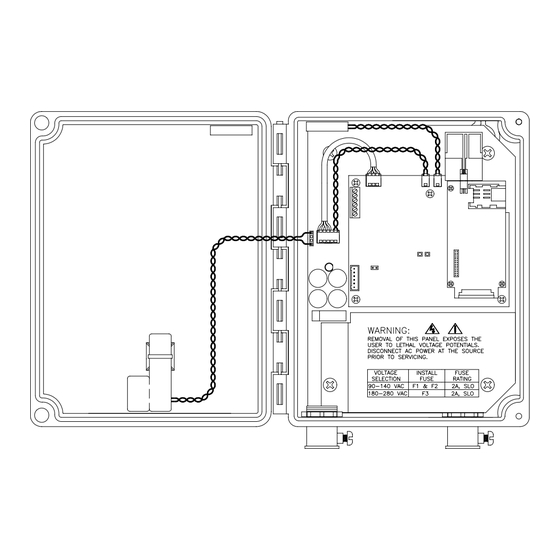
AC Power Cable Wiring Connection Figure 2-5 shows the DCM-200 with the conduit entry positions at the bottom. This illustration was shown with the metal safety shield already removed. Removal of the safety shield (Figure 2-11 and 2-12) is only to be performed after it has been confirmed that the AC mains power has been disconnected at the source. -
Page 27: Routing And Connection Of Ac Mains Power (Prior To 2006)
Figure 2-13 Routing and Connection of AC Mains Power (prior to 2006) Figure 2-14 Routing and Connection of AC Mains Power (2006 and later) 2-11... -
Page 28: Ac Line Voltage Selection
This battery pack serves to maintain short- term operation of the DCM-200 in the event of a power outage, permitting the device to call-in and report the loss of main power. The battery power connector is located at the far left-hand side of the power supply board as shown in Figure 2-15 and 2-16. -
Page 29: Battery Pack Connector (Prior To 2006)
Battery Pack Connector (prior to 2006) Figure 2-16 Battery Pack Connector (2006 and later) If a DCM-200 unit is removed from service, then the battery pack should be disconnected immediately to prevent unnecessary drain and consequent reduction in capacity. 2-13... -
Page 30: Internal Antennas
850 MHz band is being converted to digital operation by most carriers. The original DCM-200 (built prior to 2006) used a Motorola “g18” GSM cellular radio module. Production of this device was discontinued in 2005 and was replaced by the “g20”. -
Page 31: External Antennas
Figure 2-19 Installing the Quad-Band Antenna 2.11 External Antennas You may encounter marginal reception areas or locations where buildings and other obstructions block the cellular radio signal path when using an internal antenna. Provision has been made to permit the installation of an external antenna to address these situations. -
Page 32: External Antenna Kits
Every DCM-200 enclosure has been pre-drilled with a 1/4" diameter hole at the upper left-hand side of the enclosure wall. It is necessary to push out the small black hole plug and clean away any residual silicon sealant. The SMA female end of the cable is then pressed through the enclosure wall and fastened into place using the provided washer and nut. -
Page 33: Internal Circuit Boards
3 INTERNAL CIRCUIT BOARDS Power Supply Board The larger circuit board in the DCM-200 serves the dual purpose of acting as the mounting platform for the GUTC board, as well as providing the regulated DC power source for the GUTC and cellular radio module. Figure 3-1 illustrates the profile of the original power supply board (stock number 1001-0302) made prior to 2006 along with the major component elements. -
Page 34: Block Diagram Of The 1001-0302 Power Supply Board
Figure 3-2 Block Diagram of the 1001-0302 Power Supply Board Here is a brief description of these components: • Fuses F1, F2, F3: Serves to protect both the user and the electronics in case of a surge or overload condition. The fuses are also used to select the input voltage range. -
Page 35: 1001-0310 Power Supply Circuit Board (2006 And Later)
confirmed otherwise. • Connectors J1 & J3: J1 is the connector for the lithium reserve battery. J3 is the connector that routes power and the AC status signal to the GUTC board. Figure 3-3 illustrates the profile of the power supply board (stock number 1001-0310) used in 2006 and later. -
Page 36: Block Diagram Of The 1001-0310 Power Supply Board
Figure 3-4 Block Diagram of the 1001-0310 Power Supply Board... -
Page 37: Gutc Board
GUTC Board The original GUTC board with the Motorola g18 radio is shown in Figure 3-5. Figure 3-5 GUTC Circuit Board with g18 Radio... -
Page 38: Gutc Circuit Board With G20 Radio
The GUTC board with a Motorola g20 radio is shown in Figure 3-6. An earlier g18- based board can be converted to g20 operation using the adapter board shown in this figure. The conversion process is discussed in an upcoming chapter. New firmware is required when making this change. -
Page 39: Block Diagram Of The Gutc Board
Figure 3-7 Block Diagram of the GUTC Board Figure 3-8 Block Diagram of the DCM-200 System... -
Page 40: Gutc Capacitor Board Installation
GUTC Capacitor Board Installation If the DCM-200 is allowed to originate calls, and the main ac power fails, power will be supplied by a backup battery pack and the unit will immediately place a call to report an “AC-OFF” alarm. Once the call is made the DCM-200 enters a power-saving sleep mode and will remain there until ac power is restored. -
Page 41: Side View Of Capacitor Board Installation
3) See Figures 3-10 and 3-11. Align the mating connector on the capacitor board with J9’s pins and install the capacitor board. 4) Connect the power connector to J1. The DCM-200 should reset and attempt to place a call into the central computer. When the radio is activated the LED on the capacitor board should light if the board is properly aligned. -
Page 42: Top View Of Capacitor Board Installation
Figure 3-11 Top View of Capacitor Board Installation 3-10... -
Page 43: Cellular Service
Typically, the smallest available package will be 1 megabyte (1 Mb) per month. The amount of data that the DCM-200 will produce depends upon how the device is configured and what sort of data is requested from the electric meter. The amount of information exchanged on each call may range from several hundred bytes to 10’s of thousands of bytes. -
Page 44: Establishing Cellular Service For Csd
Some providers offer free long distance or no roaming charges as part of their basic plans. The final consideration is the direction of the calls. If the DCM-200 is to originate calls, then the service must support “mobile-originate” service. If the unit is to receive calls, then “mobile-terminate”... -
Page 45: Requesting A Voice Phone Number Or Sms Service
“voice” phone number then the unit can be called using this number. Otherwise most cellular providers can include SMS (short message service) as part of the package. This allows the DCM-200 to be paged with a text message (email). -
Page 46: Sim Card Installation For The G18 Radio
A SIM card allows the cellular account to be moved from one phone to another. Theft is an issue because a person could remove the SIM card from the DCM-200, install it into his or her own cellular phone and have unlimited calling access to anywhere in the world. -
Page 47: Screw Positions For The Gutc Board
Figure 4-3 Screw Positions for the GUTC Board WARNING Disconnect all power sources before installing or removing the SIM card !! For the Motorola g20 radio the SIM card connector is located below the radio. It is not necessary to remove the GUTC board from the unit. But because of the SIM card connectors close proximity to the metal safety shield it is necessary to remove the shield. -
Page 48: Sim Card Installation For The G20 Radio
Figure 4-4 SIM Card Installation for the g20 Radio... -
Page 49: Device Configuration Using Mp32
FLASH memory of the processor on the GUTC board. Certain parameters are unique to each DCM-200, such as the unit’s I.D. number, phone number or Internet address to call, cellular radio frequency, etc. Changing the firmware allows new features to be added, existing features to be changed or problems to be corrected without the need to replace components. -
Page 50: Mp32 Software Startup
Figure 5-1 MP32 Login Screen After login a window will appear to allow you to select the type of Metretek device to program (Figure 5-2). Prior to selecting the device, select the “Communication Configuration” button. In the next window (Figure 5-3) select the “Cable Comm Port” as the default, and make sure that the selected port matches the port that the cable is plugged into on the computer, such as COM1, COM2, etc. -
Page 51: Mp32 Start-Up Screen
Figure 5-2 MP32 Start-Up Screen Figure 5-3 MP32 Communication Port Configuration Screen... -
Page 52: Mp32 Configuration Screen
The original MP32 screen will now reappear and the user should select the “DCM-200” button to start the configuration process. Figure 5-4 depicts the opening screen. Figure 5-4 MP32 Configuration Screen If using the programming cable, only the READ, PROGRAM and FIRMWARE UPDATE buttons are used. -
Page 53: Configuration Settings
Check this box if the DCM-200 is allowed to originate CSD calls or Internet connections. 5.4.4 Respond to Voice Calls Check this box if the DCM-200 is allowed to answer CSD calls, or is allowed to be paged using its voice phone number. See Chapter-7 for more information about paging. 5.4.5 Respond to SMS Check this box if the DCM-200 is allowed to be paged via SMS (short message service). -
Page 54: Answer Ring Count
1-hour increments. There is no limit to the number of times the DCM-200 will attempt to place a call at this rate. Once a call is successful, the DCM-200 will return to using the primary rate and count. See Chapter-7 for further information about call retries. -
Page 55: Gprs Access Point Name
5.4.16 GPRS Access Point Name If the DCM-200 will be making an Internet connection (GPRS mode), the cellular service provider will need to provide an Internet APN (access point name). In order to connect to the Internet, the provider has its own computer equipment called a “gateway” server. -
Page 56: Max Bps
5.4.21 Parity Parity is used to detect errors in the communications between the DCM-200 and the electric meter. Its use is optional and is usually set to NONE. This setting is usually... -
Page 57: Stop Bits
5.4.22 Stop Bits This setting defines the termination method of each byte. This setting is usually programmable within the electric meter itself, and the two settings must match. It is usually set to “1”. The next configuration items appear on the Input 1/2 Configuration and Input 3/4 Configuration tabs: Figure 5-6 MP32 Input Configuration Settings Screen... -
Page 58: Programming The Configuration Using The Programming Adapter
If there are problems, review the information in Section 5.3 about the communications setup. NOTE When the configuration is changed the DCM-200 will be reset. See Chapter-7 for a description of the unit’s behavior after a reset. Programming the Configuration Over-The-Air The configuration of one or many installed DCM-200s can be changed over the cellular network. - Page 59 200’s. This information comes from the database for each device. Earlier in Chapter-4 we discussed the ability of the DCM-200 to read the unit’s phone number from the SIM card and report it to DC-2000. DC-2000 then automatically inserts this phone number into the database.
-
Page 60: Firmware Downloads Using The Programming Adapter
Firmware Downloads Using the Programming Adapter The entire operating program (“firmware”) of the DCM-200 can be updated without removing or installing memory components. A firmware file must be obtained from Metretek. After selecting the UPDATE FIRMWARE button the following screen will... -
Page 61: Firmware Downloads Over-The-Air
Section 5.3 about the communications setup. NOTE When the firmware is updated the DCM-200 will be reset. See Chapter-7 for a description of the unit’s behavior after a reset. Firmware Downloads Over-The-Air The firmware in one or many installed DCM-200s can be changed over the cellular network. -
Page 62: Selection List For Over-The-Air Firmware Changes
200’s. This information comes from the database for each device. Earlier in Chapter- 4 we discussed the ability of the DCM-200 to read the unit’s phone number from the SIM card and report it to DC-2000. DC-2000 then automatically inserts this phone number into the database. -
Page 63: Configuration Of Dc-2000 Data Collection System
Metretek’s Technical Support Department to arrange for training or if there are further questions. The DCM-200 and the ANSI C12-complient electric meter that is attached to it are viewed as seperate devices, each requiring configuration for DC-2000. Configuring the DCM-200 Start the process by selecting Remote Unit Configuration from the DC-2000 Applications Launcher. -
Page 64: Selecting A New Or Existing Dcm-200
Figure 6-2 Selecting a New or Existing DCM-200 The screen that follows has a number of tabs to choose from. The DCM-200 is a member of Metretek’s SIP (Survey Instrument Point) family. Many of the SIP settings are used in applications that do not involve electric meters and can be ignored. Here are... -
Page 65: Site Id Number
This is the device ID number of the ANSI C12-complient electric meter that will be connected to this DCM-200. If the electric meter hasn’t yet been defined, pick any ID number from the list. It will be updated automatically when the electric meter is... -
Page 66: General Information Screen
Figure 6-4 General Information Screen... -
Page 67: Interval Size
6.2.5 Interval Size When the DCM-200 is configured using MP32 (Chapter-5), a Time Interval Size had to be specified. This value is reported to the DC-2000 data collection software, and DC- 2000 will compare it to a value that it has in its database. If the two do not match, the call will be rejected. -
Page 68: Input Configuration Screen
“Low Battery” Alarm: The backup lithium battery is nearly depleted. “Unit Reset” Alarm: The DCM-200 experienced a total reset of its electronics. “Call Retry” Alarm: The DCM-200 is repeating a call that was unsuccessful earlier, usually due to cellular network problems or congestion on the DC-2000 system. -
Page 69: Immediate Alarm Notification
6.2.6 Immediate Alarm Notification When checked, this will cause the DCM-200 to place an immediate call when this alarm condition occurs. The DCM-200 must be configured to originate calls for this to work. Changing this selection will not take effect until DC-2000 has had a chance to communicate with the remote unit. -
Page 70: Configuring The Ansi C12-Complient Electric Meter
ANSI Device. This number must match the number that was specified as the “Slave Device” number when the DCM-200 was configured (see Figure 6-4). Figure 6-8 Site Information Screen for the ANSI Device 6.3.2 “IP Enabled” Checkbox Checkmark this box if the DCM-200 is to use GPRS (Internet) communications. -
Page 71: Slave Device" Checkbox
This is the device ID number of the DCM-200 that will be connected to this meter. If the DCM-200 hasn’t yet been defined, pick any ID number from the list. It will be updated automatically when the DCM-200 is configured. -
Page 72: Configuring The Data Collection Server
Configuring the Data Collection Server Once the DCM-200 and the ANSI device are configured, the data collection application will need some information concerning the Internet if using a GPRS connection. As shown in Figure 6-10, select System Configuration from the DC-2000 Launcher. -
Page 73: Enabled Checkbox
6.4.2 Internet Address This is the Internet address that the DCM-200 will use to make the connection. This address was programmed into the unit using MP32 software, as described in Chapter-5. The administrator of the data collection system usually assigns this address. -
Page 74: Internet Ports Configuration Screen
ANSI application can only use up to 55 more. Figure 6-12 Internet Ports Configuration Screen Upon completion, the DC-2000 data collection system can be started and the DCM-200 and ANSI devices can begin calling in. 6-12... -
Page 75: Dcm-200'S Modes Of Operation
GPRS connection is supported at this time. When the meter or the DCM-200 wish to connect to the data collection system the DCM- 200 will register with the cellular network, establish a GPRS data link and then switch to a transparent state. -
Page 76: Led Error Codes
Figure 7-1 Location of Unit Reset Pins If the DCM-200 has been configured to originate a call to the data collection system, the unit will attempt a call to report a unit reset alarm. LED Error Codes The two LED indicators are used to display error conditions and status. In the event of an error, the LEDs will be flashed in a pattern that represents a 2-digit number. -
Page 77: List Of Error Codes
A segment of FLASH memory could not be fully erased. A segment of FLASH memory could not be programmed correctly. The DCM-200 has been configured to place a CSD call, but there is no phone number programmed into the unit. - Page 78 There is an illegal setting in the configuration memory. For instance, the cellular radio does not support the 850 MHz range, but the DCM-200 has been configured for 850 MHz operation. A command or data received from the central computer contained an error.
-
Page 79: Led Status Behavior
Red LED Status Indicator in GPRS Mode Call Retry Strategy If the DCM-200 is configured to originate calls or Internet connections, and a call fails due to a data error or a network problem, the following retry strategy is followed: 1) The first retry will occur from 2 to 15 minutes after the original call, as defined by the Primary Call Retry Rate. -
Page 80: Behavior In Csd Mode
Primary Call Retry Rate and Primary Call Retry Count are programmed with the same number, say 7 and 7, then the following retry strategy is followed: 1) If a call fails, the DCM-200 will immediately attempt a call to the phone number or IP address that has been programmed for Counter/Status Input-2. -
Page 81: Behavior In Gprs Mode
All of this negotiation takes a certain amount of time. To reduce this time the DCM-200 can maintain access to the Internet at all times and only needs to request access to the destination server, which only takes a few seconds. This is often referred to as an “always on”... -
Page 82: Paging Via Sms Message
SMS allows short text messages (email) to be sent to a cell phone. SMS can be used to page the DCM-200 if the unit has been configured to respond to SMS messages. The actual content of the message is unimportant and is erased as soon as it is received. -
Page 83: Over-The-Air Firmware Updates
“AC-ON” condition. When the DCM-200 calls in to report a power failure it will also measure the backup lithium battery voltage. If it has reached a low level the DCM-200 will report a “LOW BATTERY”... - Page 84 7-10...
-
Page 85: Maintenance & Troubleshooting
8 MAINTENANCE & TROUBLESHOOTING Lithium Battery Replacement A special reserve battery pack is provided with each DCM-200 that maintains power to the internal electronics in the event of an AC power outage. Enough capacity exists for the battery to place over 100 emergency calls and report the power loss as an alarm condition (see Chapter-7). -
Page 86: Troubleshooting The Power Supply
Troubleshooting the Power Supply WARNING ! Potentially lethal voltages exist within the DCM-200 enclosure. Only qualified service personnel should be permitted access. WARNING To avoid damage to the electronics caused by static discharge, ensure that proper ESD control procedures are followed. -
Page 87: Troubleshooting The Gutc Board
LED flash patterns that indicate the state of the radio and of the cellular connection. If the DCM-200 can initialize the radio and has adequate signal strength, but can’t complete a connection, the problem could be with the cellular service provider. - Page 88 28-pin electrical connector is not damaged and that the alignment is correct. If any of the small screws or nylon standoffs is lost during servicing, Metretek should be contacted for obtaining exact replacements. Incorrect standoffs may cause the radio to warp and be permanently damaged.
-
Page 89: Conversion Of G18-Based Units To G20 Operation
Required Materials • Metretek’s MP32 configuration software, Version 3.4.8 or later. This is required to load new firmware into the DCM-200 to support the change from the g18 to the g20 radio. • Programming adapter cable as illustrated in back Figure 2-1. Metretek part number is 1002-0299C-001. -
Page 90: Loading New Firmware
Loading New Firmware Prior to replacing the radio, the DCM-200 will need new operating software (“firmware”) to accept the g20 radio. Chapter-5 discusses how to do this. The required firmware is 100219, Version V2.4 or later. The name of the program file for V2.4 is “100219_24.hex”. -
Page 91: Installation Of The G20 Adapter Assembly
DCM-200 board. Gently insert the interface connectors together. Make certain that all pins are properly inserted into the connector on the adapter board. Failure to do so may cause damage to the radio or the DCM-200 board ! -
Page 92: Alignment Of Adapter Assembly
Figure 9-5 Alignment of Adapter Assembly 2) Reinstall the original three screws, spacers and washers as shown in Figure 9-6. The DCM-200 board already has non-removable nuts built in to the board. Figure 9-6 Installing Mounting Hardware 3) If the original antenna is going to be replaced by the quad-band antenna then... -
Page 93: Installing The Quad-Band Antenna
Figure 9-7 Installing the Quad-Band Antenna Remove the paper backing from the adhesive strip on the back of the antenna. Position the antenna on the top inside wall of the enclosure just behind theTamper switch as shown in Figure 9-7. The antenna cable must exit to the right. Apply pressure for several seconds to ensure good adhesion. -
Page 94: Power-Up Check
Figure 9-8 Installation of Antenna and SIM Card 5) Reconnect the power cable to the J1 connector. Figure 9-9 Reconnection of Power Power-Up Check The unit should behave exactly as it did with the g18 radio. -
Page 95: Direct Radio Communications Guide
A minimum of three lines is required for the connection between the DCM-200 and the computer or dumb terminal: a line to transmit data to the DCM-200, one to receive data from the DCM-200, and common. The DCM-200 does not support hardware handshaking. -
Page 96: Starting Direct Radio Communications Mode
6) You can now directly issue commands to the Motorola radio and observe its responses. A list of supported commands can be found in Motorola’s 98- 08901C39 manual (g18 radio) or 98-08901C68 manual (g20 radio). 7) A reset or a power cycle will return the DCM-200 to normal operation. 10-2... -
Page 97: Location Of The Reset And Call Jumpers
Figure 10-2 Location of the Reset and Call Jumpers 10-3... - Page 98 10-4...
-
Page 99: Safety And Esd Information
At the time of this publication no hazardous area safety approvals have been received for the DCM-200 product. It is therefore necessary to ensure that the product is only installed at locations that are classified as ‘safe area’ sites. Safety barriers must be utilized if it becomes necessary to route any cables into a hazardous area boundary. -
Page 100: Esd Handling Precautions
11.3 ESD Handling Precautions Any electronics device contains components sensitive to ESD (electrostatic discharge). For example people experience up to 35kV ESD, typically while walking on a carpet in low humidity environments. In the same manner many electronic components can be damaged by less than 1000 volts of ESD. -
Page 101: Technical Specifications
Enclosure Mounting Pattern (See Figures 2-2, 2-3 & 2-4) Width: 4.00 inches (10.2 cm) Height: 8.94 inches (22.7 cm) Max bolt size: 5/16 inch (7.5 mm) DCM-200 Weight (with backup battery) 3.6 pounds (1.6 kg) Backup Battery Pack Type: Lithium in parallel with high-energy capacitor. Voltage: 3.67V Capacity: 1.1Ahr. - Page 102 Motorola Model g18 Tri-Band GSM GPRS FCC ID# IHDT6AC1 Metretek Stock Number 1015-0184-001 Cellular Radio (g20): Motorola Model g20 Dual-Band GSM GPRS FCC ID# IHDT56DB1 Metretek Stock Number 1015-0199-001 (850 / 1900 MHz) Metretek Stock Number 1015-0201-001 (900 / 1800 MHz) 12-2...
- Page 103 Antenna (external kit): 1850 – 1990 MHz, Metretek Stock #1014-0042-003 10.5” (25.4 cm) cable 1710 – 1880 MHz, Metretek Stock # 1014-0042-002 890 – 960 MHz, Metretek Stock # 1014-0042-001 824 – 894 MHz, Metretek Stock # 1014-0042-004 Antenna cable only: 42”...
- Page 104 12-4...
-
Page 105: Ascii-Hex-Decimal Conversion Chart
13 ASCII-HEX-DECIMAL CONVERSION CHART 13-1... -
Page 106: Warranty Information
Metretek inspects and finds reasonable evidence that a defect in material or workmanship exists. The buyer shall provide the labor required to remove the defective hardware and install its replacement at no charge to the seller.
Need help?
Do you have a question about the DCM-200 and is the answer not in the manual?
Questions and answers